References to earlier prototypes have been popping up ever since I ruthlessly slit DVI cables to force DIL8s onto some of their pins a decade ago:
https://www.google.com/search?q=EDID+Inserter
Surprisingly the EDID Inserter hasn't become an off-the-shelf item over the years, probably because most have the problem at (or rather from) some point in time (and of their wiring) but cannot fathom this is what solves it (and even exists).
With every new generation of connectors, HDMI, DisplayPort and then their Mini and Micro incarnations, the pitch keeps shrinking further towards the physical limits of my vision ... and soldering station.
Now that the current crop of equipment requires DisplayPort and HDMI sources to be connected to an HDMI screen through the trusty old DVI KVM switch in one place, and a 4*2 HDMI matrix in another (i.e. in a configuration as depicted for the "less affordable" http://www.altronics.com.au/p/a3610-edid-ghost-emulator-writer-hdmi in the bottom diagram), I had to resort to the surface-mounted SOIC version to keep using the Microchip 24LC22A 256*8-bit E-EDID EEPROM: http://ww1.microchip.com/downloads/en/DeviceDoc/21683B.pdf
Alternatives might be the STMicroelectronics M24C02 at even smaller pitches and wider voltage ranges http://www.st.com/content/ccc/resource/technical/document/datasheet/b0/d8/50/40/5a/85/49/6f/DM00071904.pdf/files/DM00071904.pdf/jcr:content/translations/en.DM00071904.pdf,
or ON Semiconductors CAT24C208 for one with (DIP-)switchable memory banks http://www.onsemi.com/pub_link/Collateral/CAT24C208-D.PDF.
Arduinos have been considered for emulation since http://media.blackhat.com/bh-eu-12/Davis/bh-eu-12-Davis-HDMI-WP.pdf (pages 14, 20 et seq.), cf. http://www.chrisbot.com/i2c-and-monitor-ddc.html and
https://forum.arduino.cc/index.php?topic=359255.0, but they end up being bulkier and probably only required for the trickiest cases.
Our circuit will thus be as simple as (or even the bare IC more simple than) this:
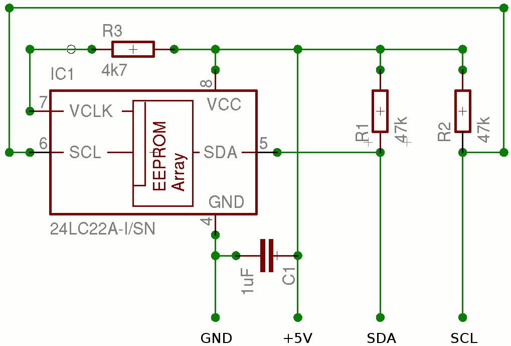
So we'll want to be near the PC's video output (source) with a better chance to make the savings on capacitor (datasheet recommendations notwithstanding) and pull-ups (still required with DVI, but can apparently be expected internal to HDMI outputs these days) as imposed by the constraints of space.
Assumptions such as "video card was not putting out enough power for the chip" in http://www.mtbs3d.com/phpBB/viewtopic.php?f=26&t=19607#p152335 might actually indicate insufficiently stabilized voltage, i.e. need for a capacitor at the far (monitor) end.
Some superbly skilled solderers may want to integrate the EEPROM directly into a DisplayPort converter such as http://www.ebay.com/itm/Display-Port-DP-Male-To-HDMI-Female-Adapter-Converter-Adaptor-for-HDTV-DL-/291663354747: Only plugs properly (on my gear at least) with the plastic shell removed anyway, and based on the ParadeTech PS8121E, which actually buffers EDIDs itself but cannot be programmed to keep them across power cycles (unplugging) with the scarce information from its Product Brief http://paradetech.wpengine.netdna-cdn.com/wp-content/uploads/2009/06/PS8121E-Product-Brief-20111020.pdf.
For those who prefer wires to work on, and in any application that requires a more flexible HDMI in-line EDID Inserter, the rotating plug adaptors come in handy at just above a dollar, e.g. http://www.ebay.com/itm/180-HDMI-1-4-HDMI-Male-to-HDMI-Female-90-270-Rotating-Adapter-Connector-HDTV/162211579564 - my most recent prototypes are based on these, which allow one of the 4 plastic shell halves to be removed fairly easily (as in my pictures).

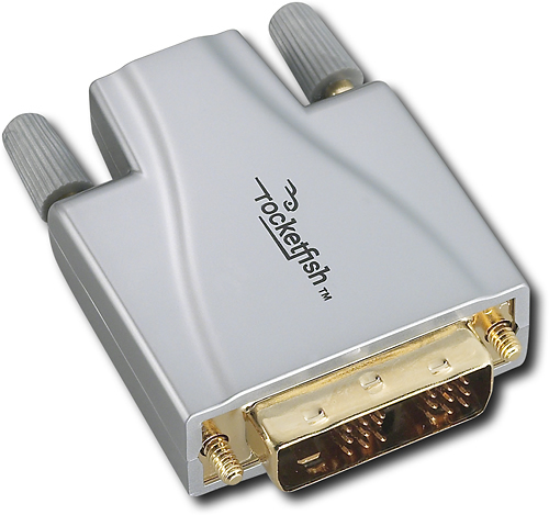
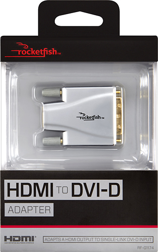
If you need HDMI to DVI on the far (monitor) end of the cable (probably requiring the pull-up resistors and capacitor as above), the RocketFish RF-G1174 https://www.rocketfishproducts.com/pdp/RF-G1174/9205898 might be suitable and a little more spacious, if you can get hold of one (maybe only in the US or Canada).
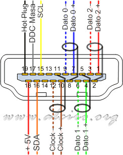
 http://www.gridgit.com/post_hdmi-pin-diagram_502138/ and https://www.flickr.com/photos/jmarcd2/ provide some good illustrations of the HDMI connectors we'll be working on, in particular this female front (receptacle) = male from rear (PCB/solder side) view: