The amplifier I used in this project is an old 2.1 PC amp.
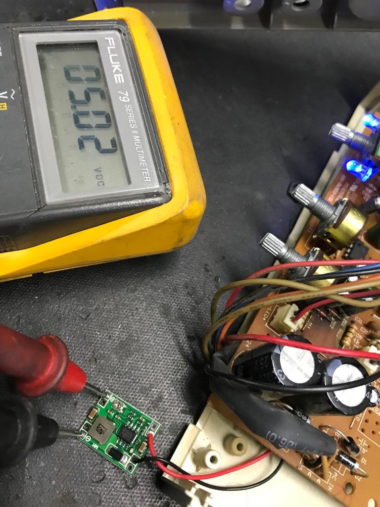
Theoretically, any audio amplifier can be used to make it multiroom capable and save you lot's of $$ compared to the readily available solutions. This project will cost you around $45, and as a standalone amp, you can stream audio to it from your phone or network server. It also plays internet radio stations.
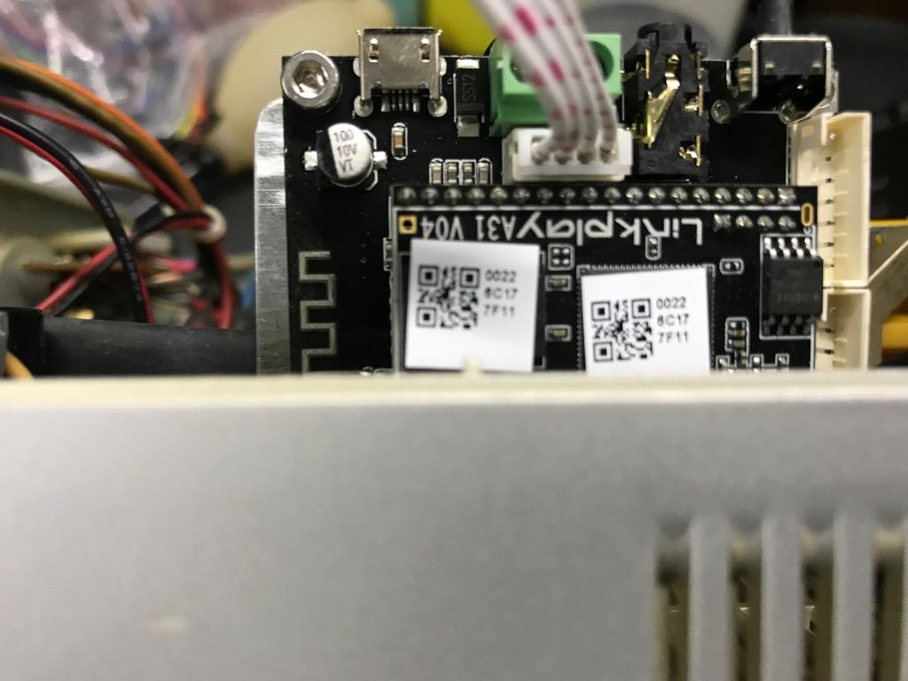
When you really want, you can buy an IR remote with the Arylic board, so you can control the music source presets, radio stations and audio settings, but with your phone you can do the same.
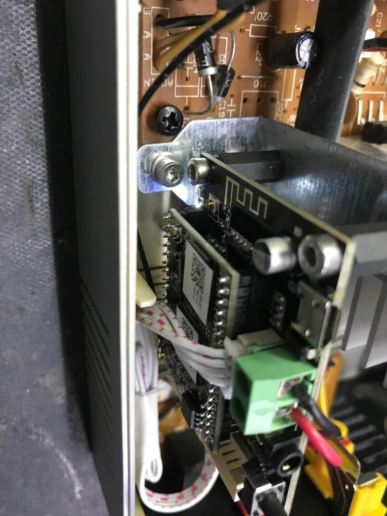
With a few handy hands and some patience you can build this on a rainy Sunday afternoon.
So don't throw out that old amplifier you never use anymore!!


 Bob Darlington
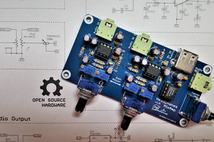
 core weaver
 Jorj Bauer
 ronald