 makeTVee
The PCB has a center hole and some cutouts for the components.
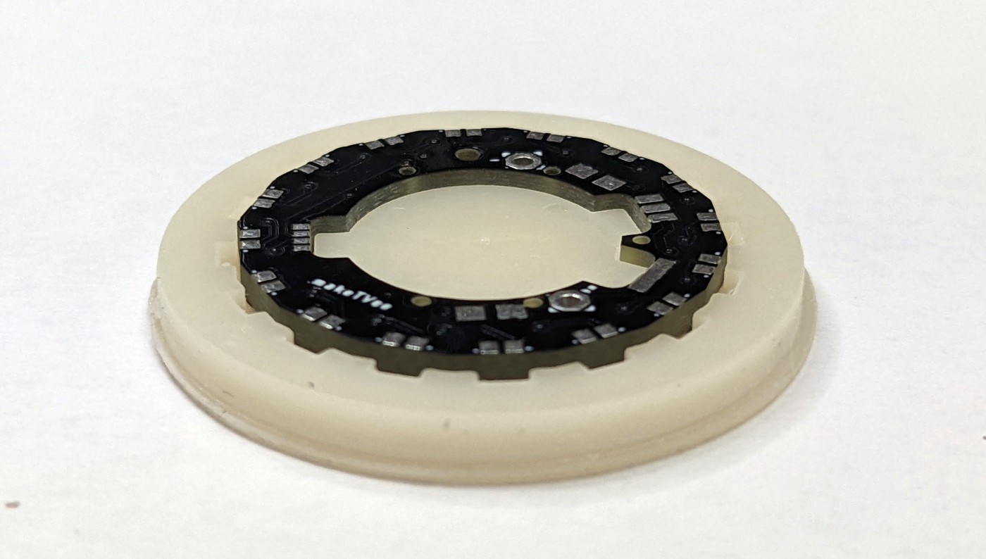
The LEDs are placed first using a resin printed jig. Matching holes are holding the LEDs in place while soldering one side to the PCB.
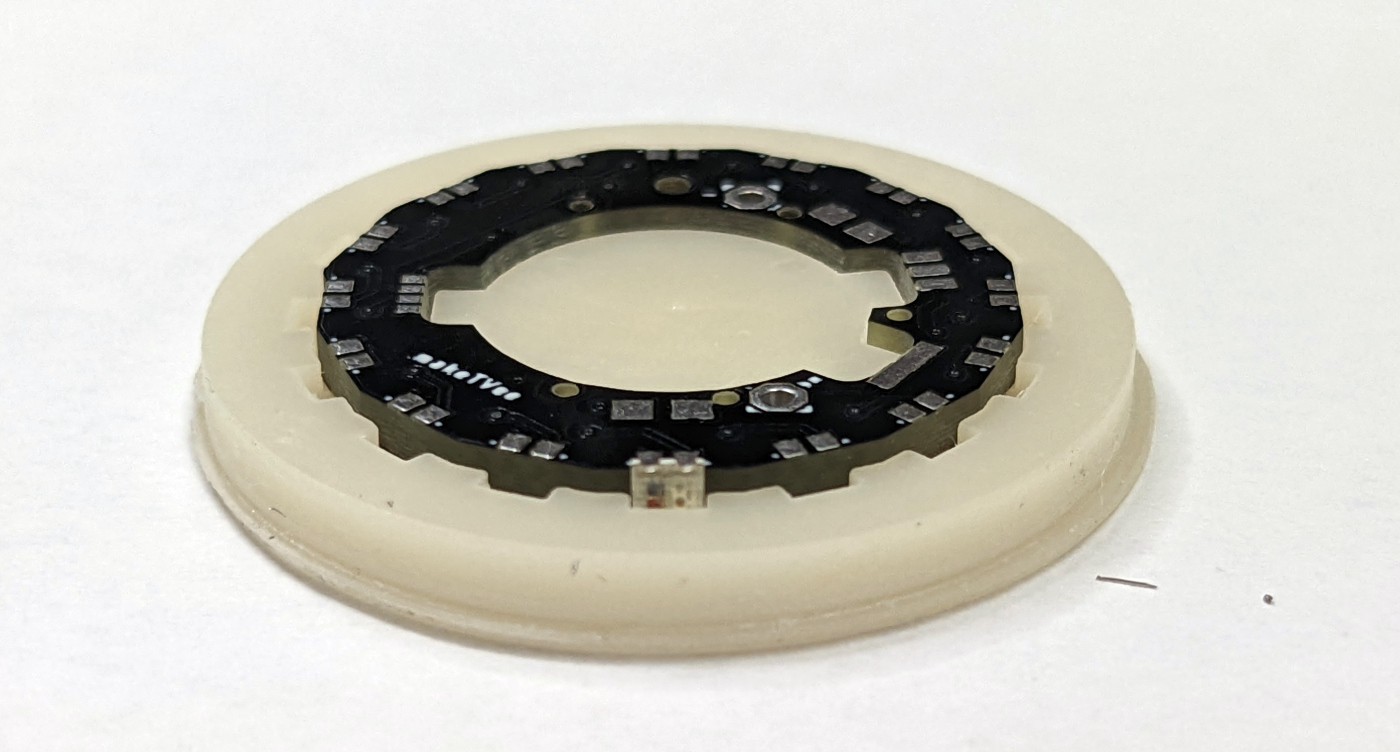
When all LEDs are soldered to the top
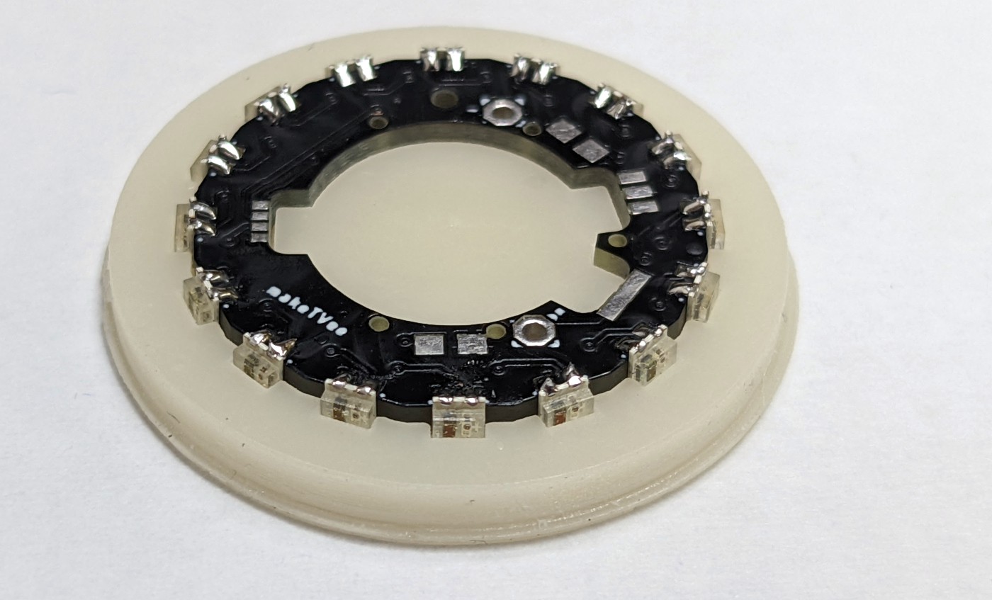
the PCB is removed from the jig and the bottom side is soldered.
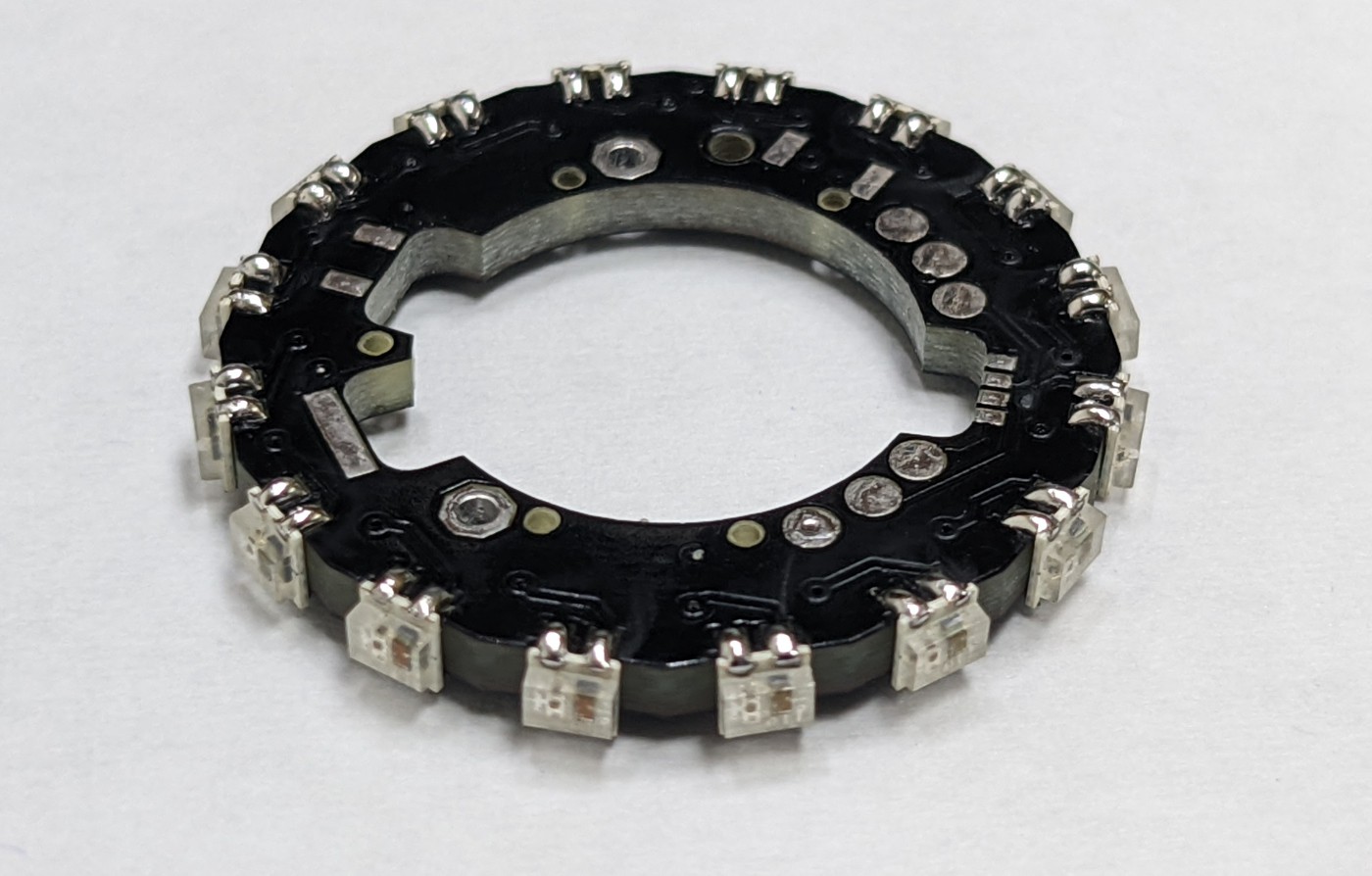
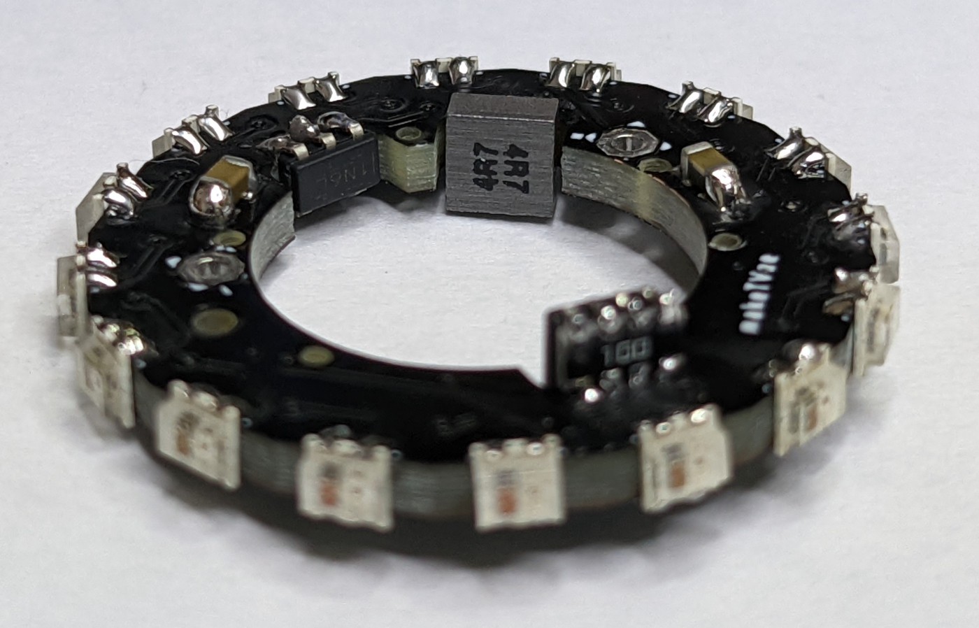
The ATtiny 45 is solder in a notch of the PCB in 90° orientation by using two resistor nets (10 Ohm), one per side.
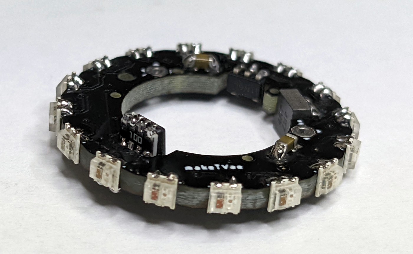
The booster converter with the inductor are also solder 90° with corresponding pads on top and bottom layer. If the battery voltage drops below 3.6V, the blue LEDs of the WS2812B stop working, therefor the booster is used to ensure a proper voltage level.
Discussions
Become a Hackaday.io Member
Create an account to leave a comment. Already have an account? Log In.