 Nick Rehm
FLIGHT CONTROLLER:
A standard flight controller like betaflight or ardupilot will only get you to the standard tricopter with forward flight capability. The controlled spinning flight mode is out of the question without significant modification, and I have no idea how to achieve that with those firmwares, so good luck!
I personally use and recommend my opensource flight controller dRehmFlight VTOL, which runs on a Teensy 4.0 microcontroller and uses easy to understand Arduino code. You will need to configure the control mixer yourself to accommodate the tricopter mixing. Watch the comprehensive tutorial videos to learn how to do this. You will also need to make code modifications to fade out closed-loop control at higher spin rates, and program in the spinning directional control shown in the third video. If this sounds too difficult or you are already confused, this project is probably not for you.
Code and more details: https://github.com/nickrehm/dRehmFlight
PARTS LIST:
- Radio: https://amzn.to/3PqNgQv
- Motors: https://amzn.to/3RLTBaP
- ESC: https://amzn.to/3RJMCPJ
- Battery: https://amzn.to/3IU4iUU
- Tilt Servo: https://amzn.to/3RFrVnU
- BEC 5v Supply: https://amzn.to/3yL3ugg
- Teensy 4.0: https://amzn.to/3IR29ZW
- Teensy 4.1 (if 4.0 is out of stock): https://amzn.to/3c1OSSw
- IMU: https://amzn.to/3Oje9og
- Carbon Fiber Arms: https://amzn.to/3IUgi8D
- Bearings: https://amzn.to/3OpRDd7
- Magnets (for nose cone): https://amzn.to/3zkFlyo
- 4mm M3 Setscrews: https://amzn.to/3IRXreD
- Misc. M3 Fasteners: https://amzn.to/3yToul1
All of the links above are Amazon affiliate links. I receive a small commission for every product purchased at absolutely no cost to you.
3D PRINT INSTRUCTIONS:
.STLs are included in the 'Files' section of this page with required quantities listed in their file names. PLA, PETG, or ABS plastic will work just fine. The nose cone fairing may be printed in LW-PLA to reduce weight.
Solid infill:
- collar
- gear_arms
- gear_servo
- motor_mount
- servo_mount_spacer
- nose_cone
30% infill:
- center_hub_cap
- center_hub
GENERAL ASSEMBLY INSTRUCTIONS:
- Press fit bearings into center hub, 2 per arm mount.
- Press fit magnets into top of the center hub.
- Slide magnets into the nose cone slots, noting the polarity to match with the center hub. Tack them in place with hot glue to prevent from sliding out.
- Slide the servo mount spacer parts over the servo mounting brackets; these provide proper offset of the servo from the center hub to give proper bevel gear alignment inside the hub.
- Use M3 hardware to fasten the servo to the center hub and install the servo bevel gear on the servo.
- Slide the 10mm carbon tubes through the bearings.
- From the inside of the center hub, slide the collar over the carbon tube, then the bevel gear.
- Use the M3 setscrews to tighten the bevel gear on the very end of the tube. Slide the tube all the way in to tightly meet the servo bevel gear.
- Use the M3 setscrews to tighten the collar so that the arm can not back itself out.
- Slide the motor mount on the outside of the carbon tube and tighten using the M3 setscrews. Adjust all three motor mounts so that they align perfectly vertical.
- Install motors and route wiring through small access holes into the center hub.
- Install electronics; use double-sided foam tape to adhere ESC, flight controller, receiver, etc. to and around the servo protruding from the top of the center hub.
- Use velcro cable ties to secure the battery to the center hub cap. Install the center hub cap with M3 hardware to seal the bevel gears within the center hub.
- Cut the wings from 5mm dollar tree foamboard. Remove paper from one side and fold over centerline. Hot glue to the carbon tube arms and bevel the trailing edge. The small marks on the wing cutout are to mark where the carbon tubes should align; use these to mark the wings when you glue them to the arms.


 Adam Redfern
 Brian Brocken
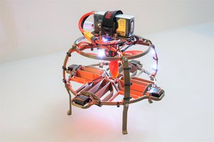
 Benjamin Prescher
is there any cheaper option for the esc?