 core weaver
Intro - "every First Step of a journey"
each project, no matter what purpose it may serve, is like a ride into another realm. Some are jobs and you just wanna do it and be done with it. Some are hobby things, they'll never materialize into finished products. You're tinkering, experimenting, you discover or try new stuff. That's where you'll get your true knowledge from.
..and then, there are those things you've been dreaming about, you know .. we all hav'em Some of us have "to do - wish" lists longer than a kid's letter to Santa. Ya know those dream projects which are delayed indefinitely. The reasons are mostly "trivial": the lack of tools, or proper equipment, or a place big enough and well ventilated where no one is complaining about fine saw dust or welding fumes, or time, or money or.. And still.. you keep waking up, adding yet another project to that secret list which is already crowded, sighing, whispering to yourself .. "ONE DAY!"
[...]
Then one day you start zeroing in and you realize that you might have what you need, you can buy the rest, and you'll manage to manufacture whatever complicated parts you envisioned for your new "baby".. and then you finally start putting time and passion into your dream.
That's when the ride begins.
And that's what you're gonna remember for the rest of your days.
Not the sweat you've sweated, or the time you've invested, the money or all the other sacrifices you've made, not the hundreds of micro cuts you've inflicted on yourself when polishing metal or the soldering fumes or the countless back and fort moments from despair to relief, when you hit a new stone on the road, not the social events you've missed or the brainstorming / debugging sessions at 2AM in the morning after a long, exhausting day.
When you finally hold that new shiny thing you've created in your hands, and you feel like shouting "YEEEEESSS" but it's night and you do it kinda whispering.. when you get the first look at what YOU achieved... nothing else is gonna matter anymore.
You've walked the line, you've reached the finish.. You created something. No money can buy that, and no one can ever take that from you.
It's been a hell of a ride.
To all of you out there, who've been there or will get there someday,
you have my endless respect.
Part 1 - Motivation
My whole life I've been told to stop pursuing perfection because it cannot be achieved, it's a waste of time, it's not "economical", it's just stupid. Teachers, books, bosses or team mates.
"better do something imperfect which will sell in 100 million copies than wasting your time with tiny little details no one will ever notice nor appreciate."
This time, was no one behind me and I ignored that advice, deliberately.
I pursued perfection again. Don't need to explain to anyone, don't need the admiration nor the money it will generate. This is a PROTOTYPE, and will remain a Single Unit product.
I will not release schematics nor gerber and STL files. I will not try to replicate this again nor anyone else should.
This is my humble way to say "Thank you", to my father, my life's mentor.
I owe you everything dad. Thanks !
Part2 - The Inspiration
I was a teenager when a game called Fallout came out. That concept, the feeling, the game play, the music, the atmosphere it generated got me mesmerized. Then came Fallout 2 which was at least as good as it's predecessor.
Disclaimer: All the content from Fallout 1 & 2 (published and developed by Black Isle Studios and Interplay) belongs to Bethesda Softworks.
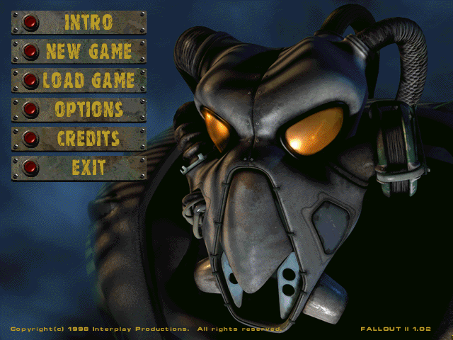
If I was secretly inloved with old technology and post-apocalyptic survival scenarios I didn't know it till I played those games.
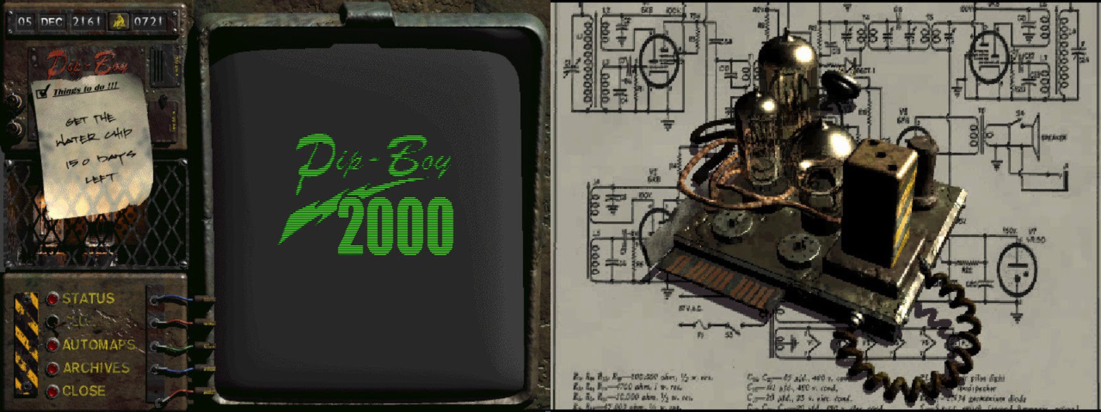
Imagine living in a desolate wasteland, scraping for everything which could prove useful, wires, empty batteries, broken machines which can be taken apart and repurposed. In those Fallout vaults, computers and old-times tech were still functioning, powered by nuclear cells, reminding of the great era which has long passed.
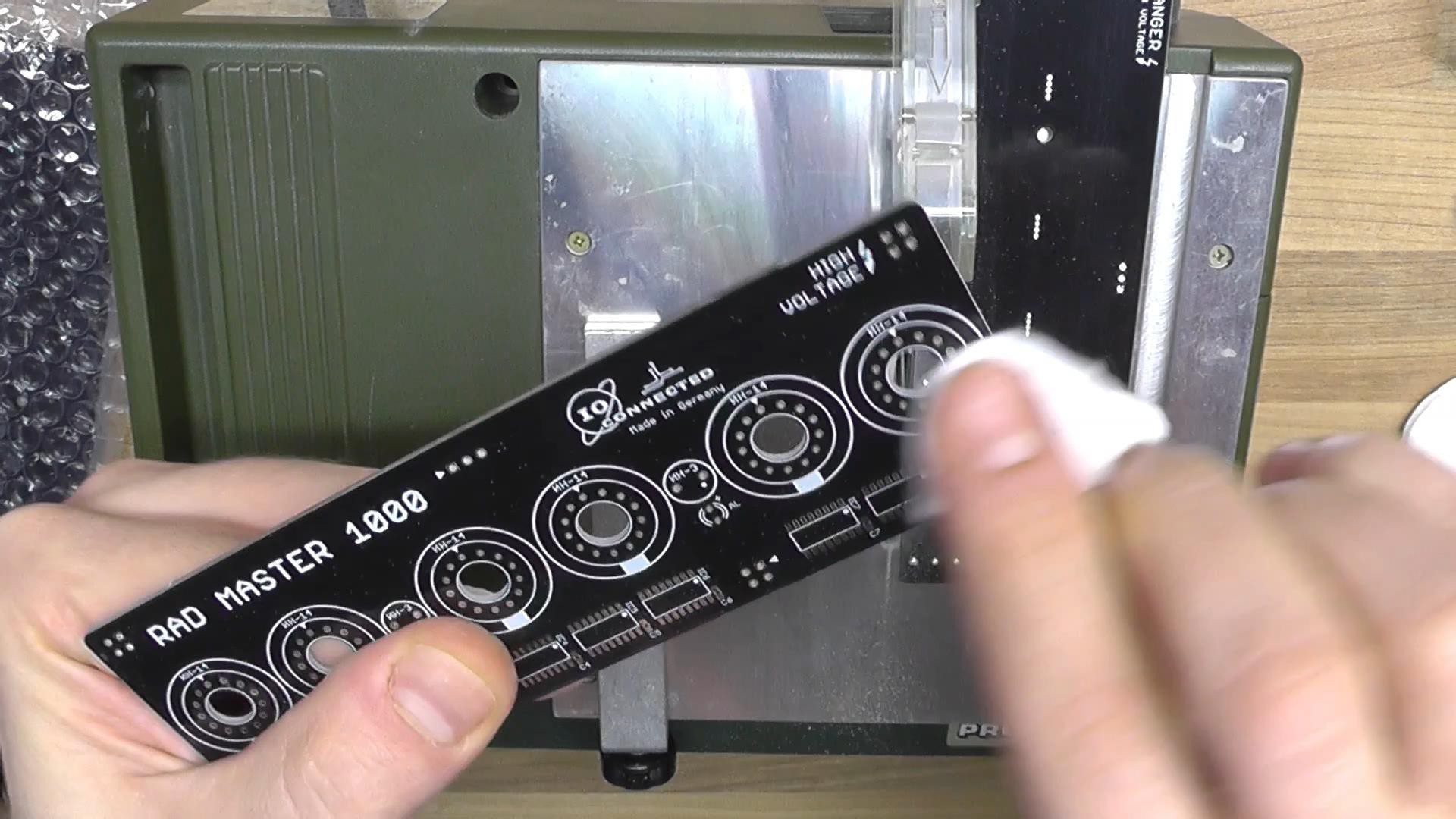
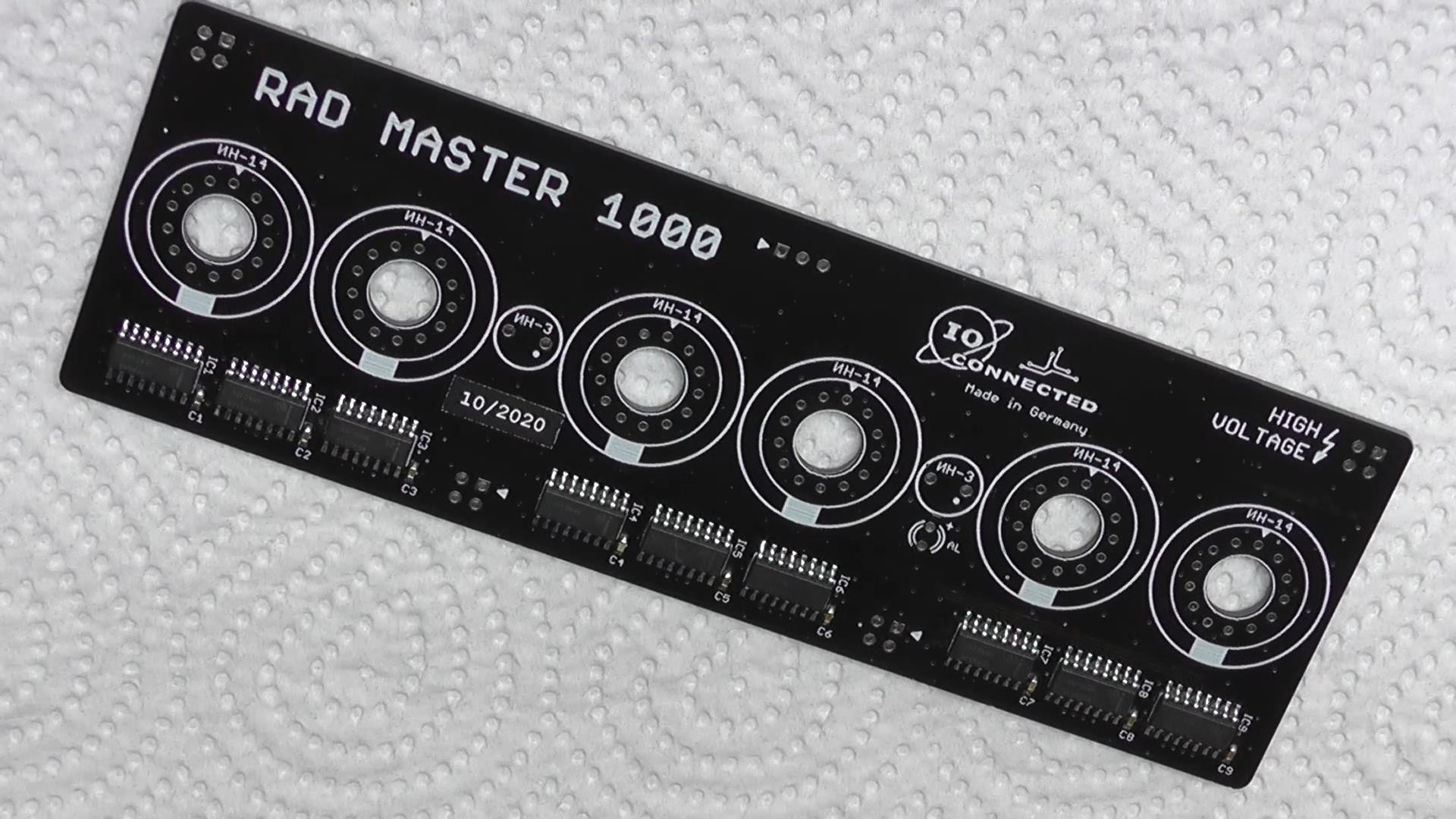
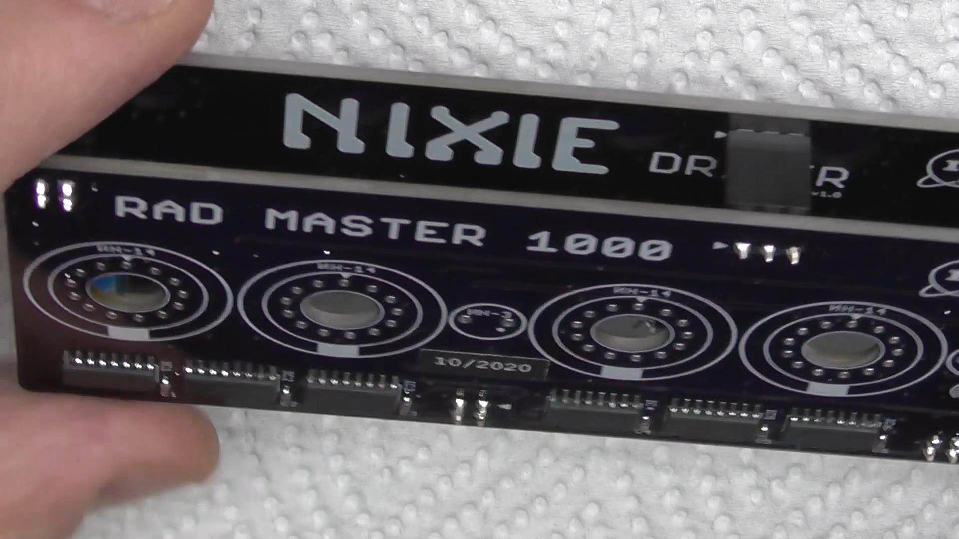
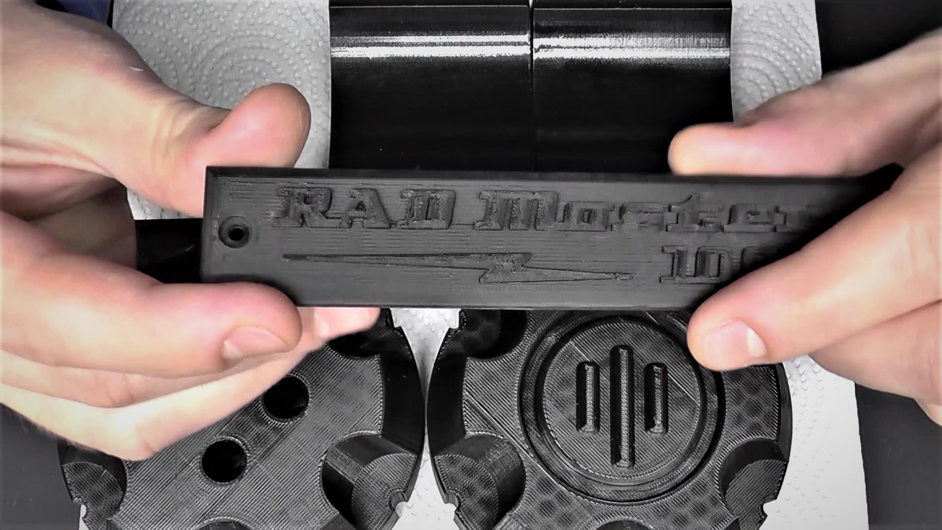
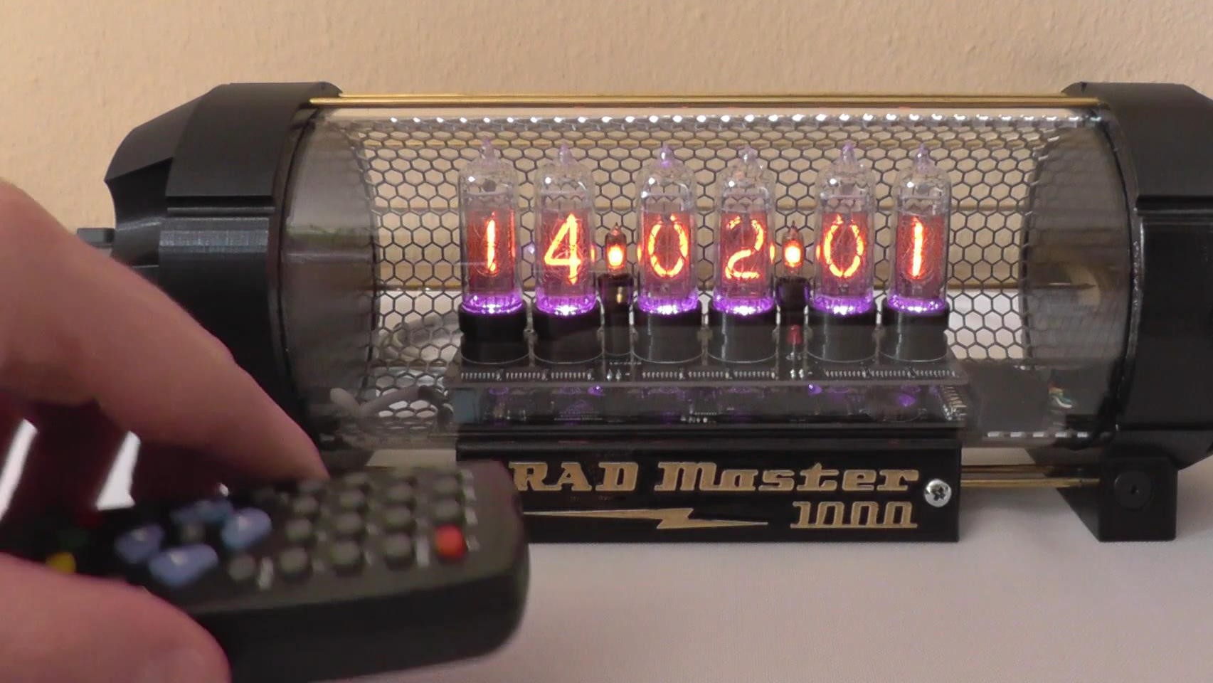
That was the exact feeling I've tried to replicate in my RAD Master 1000.
I used glass, metal and some 3D printed parts for the case. I would've so much preferred to make the case out of milled / anodized aluminum, or casting brass or stainless steel. I don't have a CNC or a lathe or a forge where I can melt metals. I didn't want to get those fabricated by someone else. So I 3D printed those parts using a high "infill" setting to add a bit of weight and make it a little bit heavier.
As for the PCB, I could've use ENIG so the writings and logos would've been in gold. Maybe it would've looked nice, but I think it would've not fit the concept. It would've been a little bit too flashy, too luxurious.
The only thing I borrowed from someone else, in this design, was the way I designed the power supply.
I liked the idea of using two transformers to step down and up again to almost 200V. I didn't invent that, and I could've built the power source entirely different. But like I said, I liked that idea and since I already had a couple of those small transformers I decided to go with this solution.
Everything else on this project is my own approach. The way it looks and feels, the schematic, the PCB, the separate driver board..
I tried to build it as it should be built. I respected it from the beginning when it was just a sketch on piece of paper, and through out the whole fabrication process. Even if it's not perfect, and I know it's not.. still, I came a step closer.
I learnt a lot and it was a very rewarding journey.
Part 3 - Getting ready
I never used Nixie tubes before. I played with some nice VFD and I built several different Geiger Müller Counters using russian tubes. But building something with nixies was something I always wanted. And I didn't want to use the new ones (China made) so I bought 6 original IN14 and 2x IN3 tubes from Russia. The parts for this project are from 3 different continents.
A lot of electronic components came from the US. Others are bought from Germany. I made the PCBs in Hong Kong, and bought some parts from Taiwan. The glass cylinder was hand made by a glass manufacturer also in Germany. The metal parts are also from EU (Germany or Czech Republic) and the printer's filament came from main land China.
I started designing the power source knowing that I will need aprox. 180V DC to light up the tubes. I calculated and simulated everything before getting the actual tubes. The old documentation was in russian (hand written and poorly scanned) and it was not very useful. I discovered a nice website dedicated to nixie tubes and got a lot of datasheets from there.
Another thing I should mention here, I didn't want to use driver ICs for the tubes. They're pretty hard to get, pretty expensive too and I guess there was also a little bit of masochism too, choosing to hand solder almost 80 SMD transistors as well as all the other components.
So I bought the High-Voltage transistors which I use to drive each digit of the tubes, and got them in both SOT23 and TO92 (though-hole) packages. I wanted to be able to experiment first, before sending the PCBs to fabrication.
Part 4 - GO !
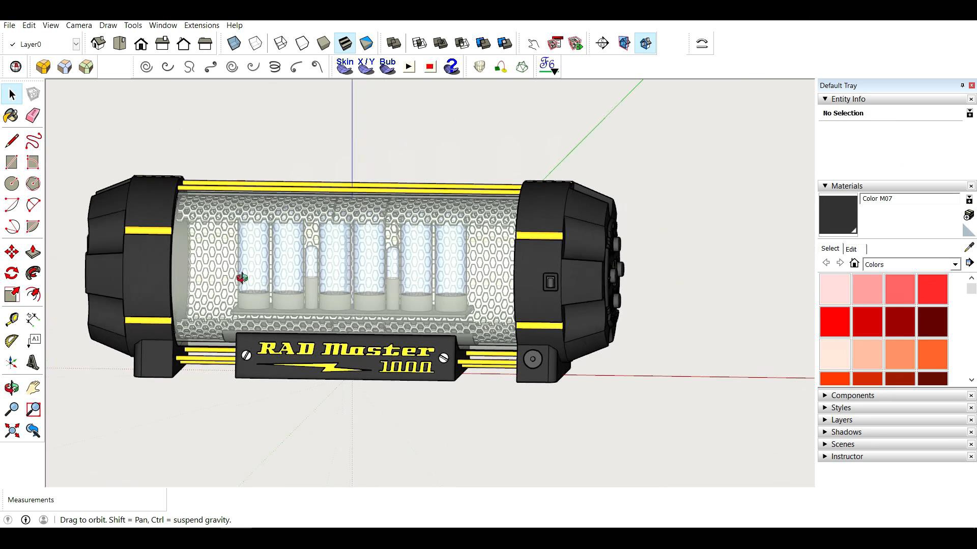
The parts were starting to arrive. And I already had a pretty detailed idea of I wanted the clock to look like. I did all this in weekends and after hours, mostly late at night. While I waited for the parts I worked on the case design (google sketch up).
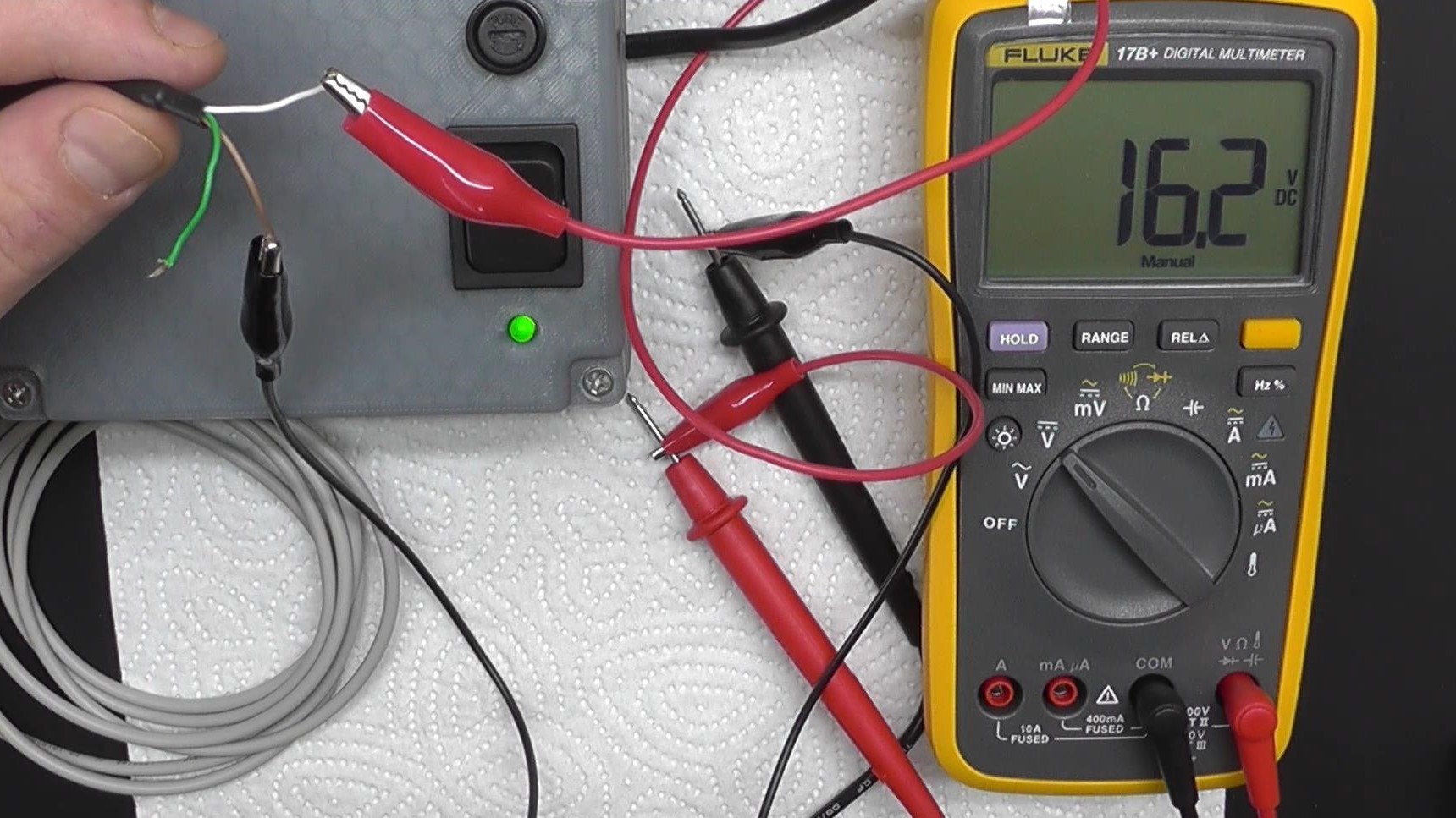
I ran some experiments with the power supply and as soon as I got the tubes and the transistors I was able to discover that the output voltage (178V) of my PS was falling under 120V as soon as I was supplying more than 2 digits. So the current was too small and I had to order a new small foot print transformer and modify the ratio. The idea is to drop the main voltage (in my case 230V AC) to 9V or something similar using a first transformer. And then use another transformer inverted (primary<>secondary) to get the voltage high again to aprox. 140V AC. After rectifying, the voltage will get to around 200V DC. If the transformers are too small the current will also be to small. The digits are drawing around 2.5mA so it took a little bit of try and see till I found the right transformers. The second output of the power source (12V DC) is stepped down and regulated by SMPS circuitry on the driver board, to get the 5V DC needed by the rest of the electronics.
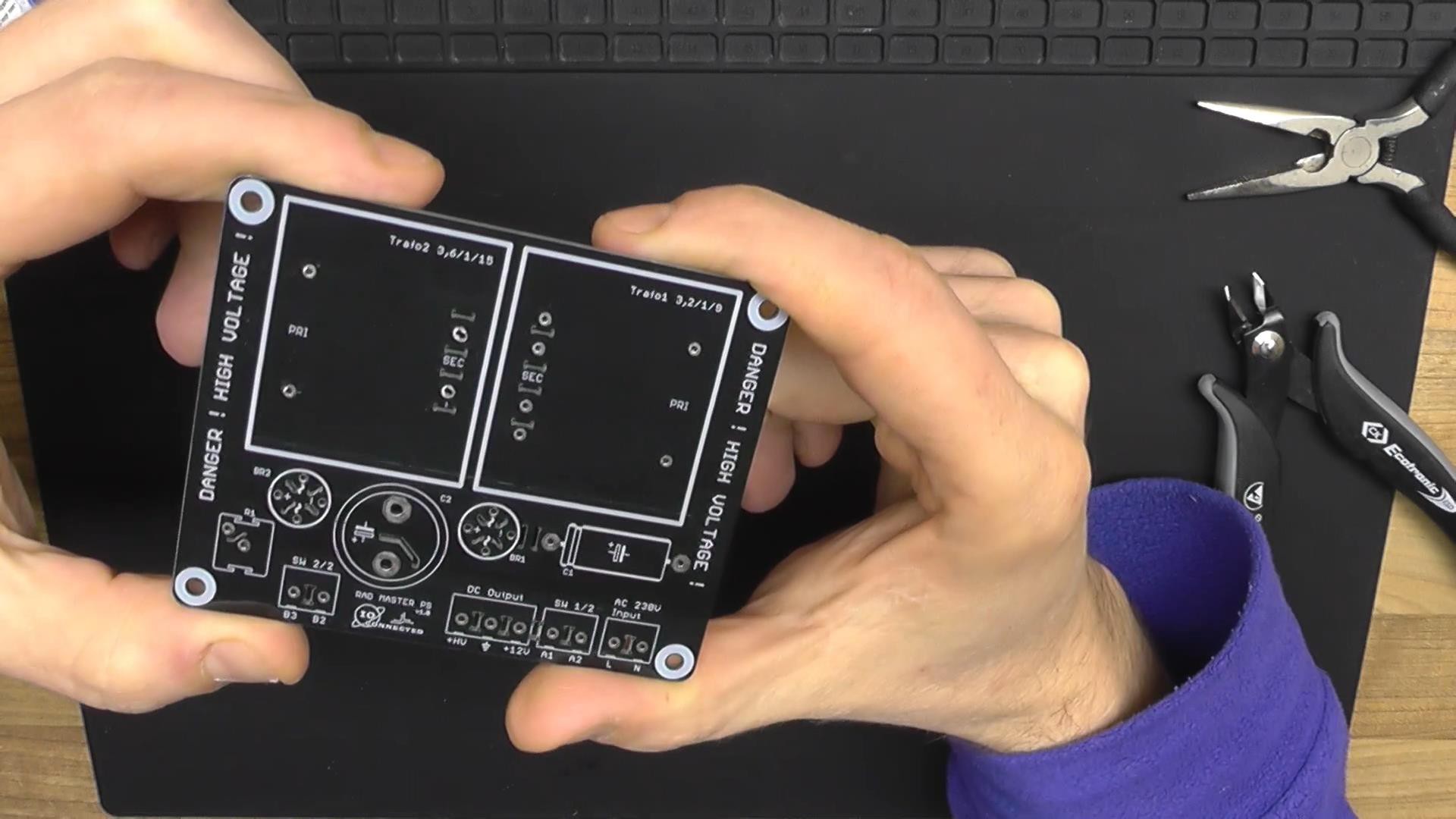
When I got the PS ready I made a board for it and sent it to fabrication along with the other 2 PCBs, one for the driver circuit and another one for tubes which sits on tops.
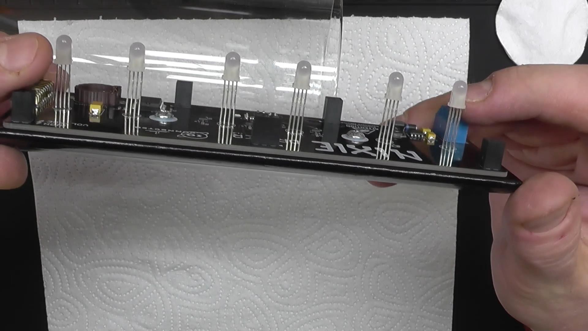
All the parts I used on the driver board and the nixies board are SMD packages with the exception of 1 TH LED for the Alarm, the RGB LEDs which are illuminating the tubes from below, the piezo buzzer and the connectors.
The Power supply uses THT components.
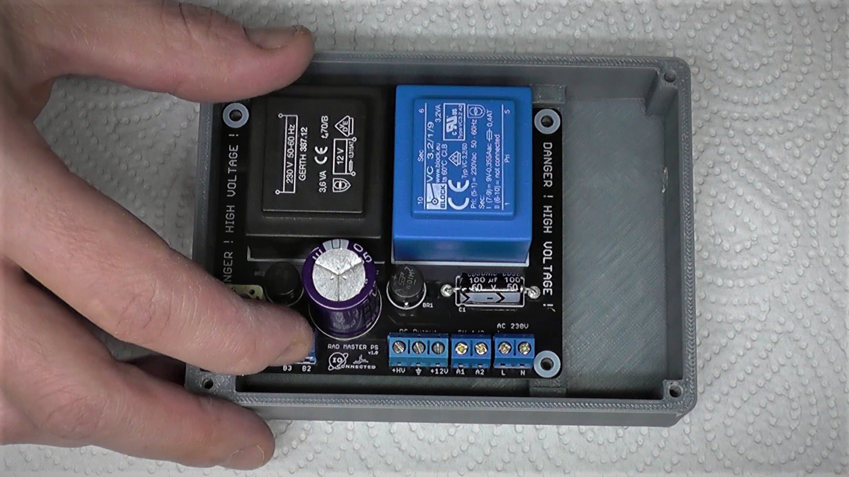
I added a sturdy DPDT switch and a power resistor to rapidly discharge the HV capacitor when turning the supply off. Then I designed and printed a case for the whole thing.
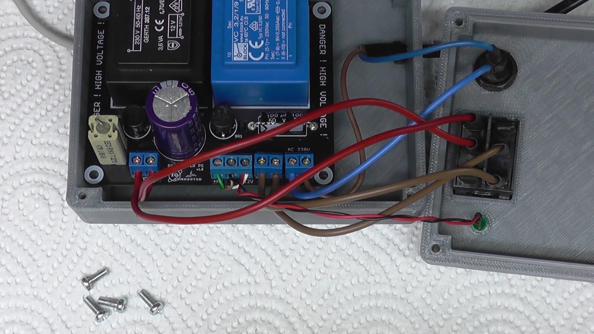
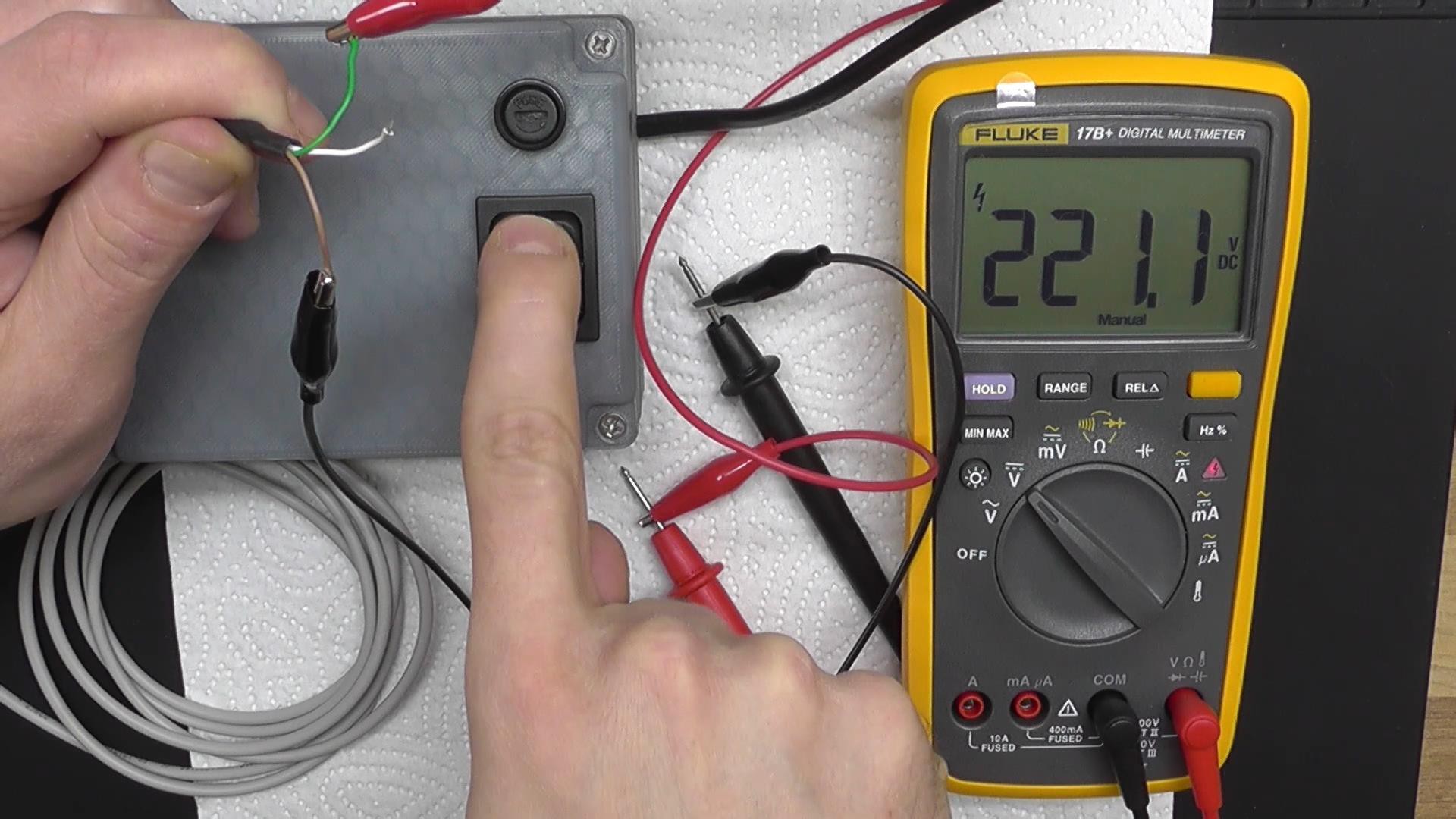
The High Voltage output is around 220V without load. With 6 of the clock's Digits and the separation points ON, the voltage drops at about 180V.
Two more pictures of the dual output power supply (16V DC / 220V DC):
After finishing and testing the Power Supply I started to work on the 2 main PCBs of the clock. The nixies PCB and the driver board.
They were panelized and I did cut them my self.
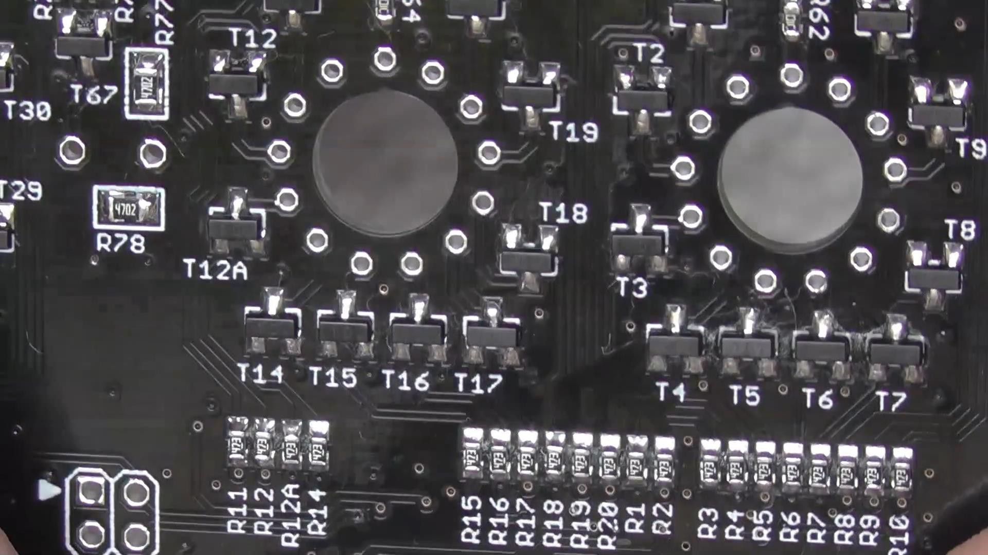
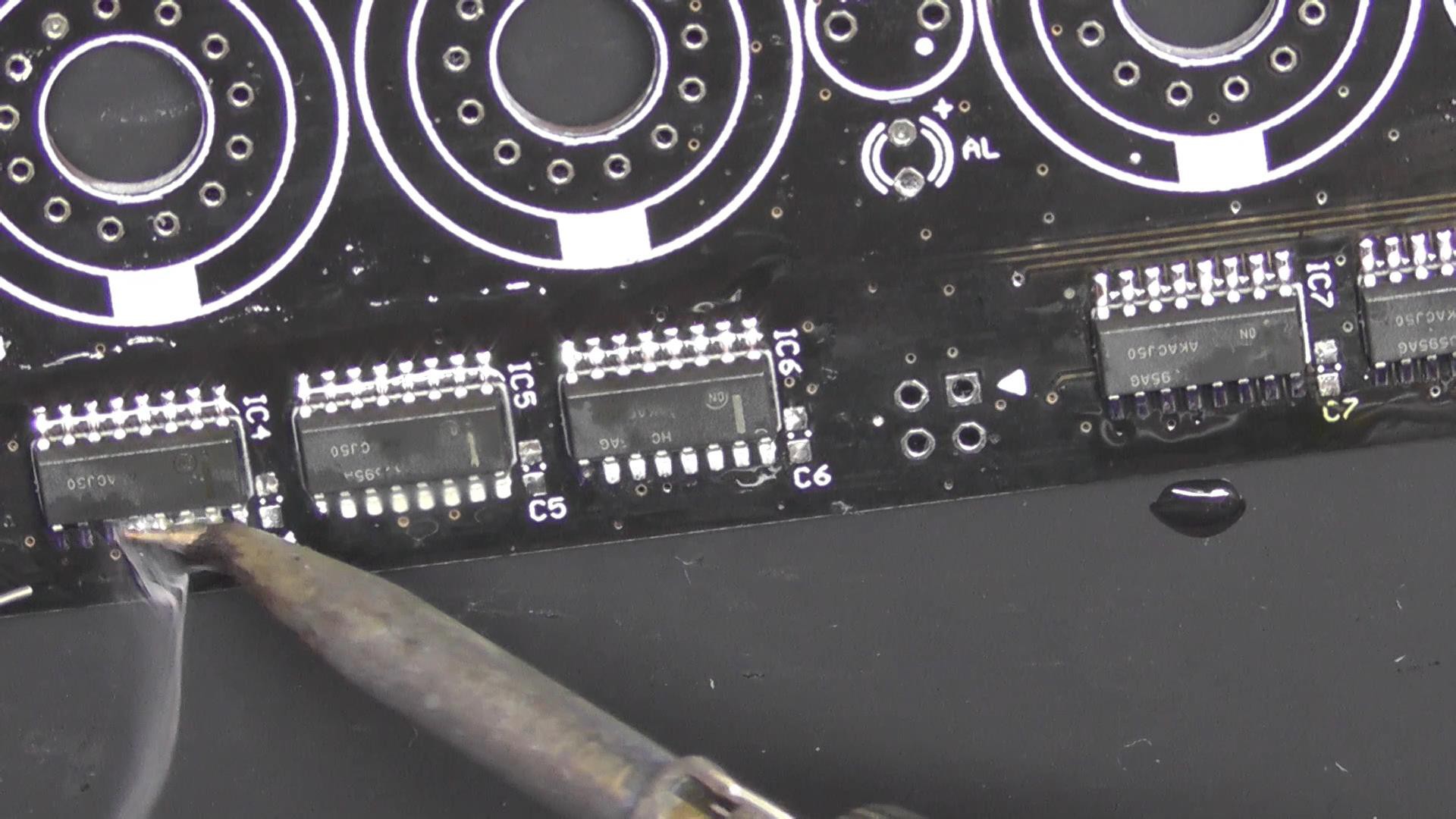
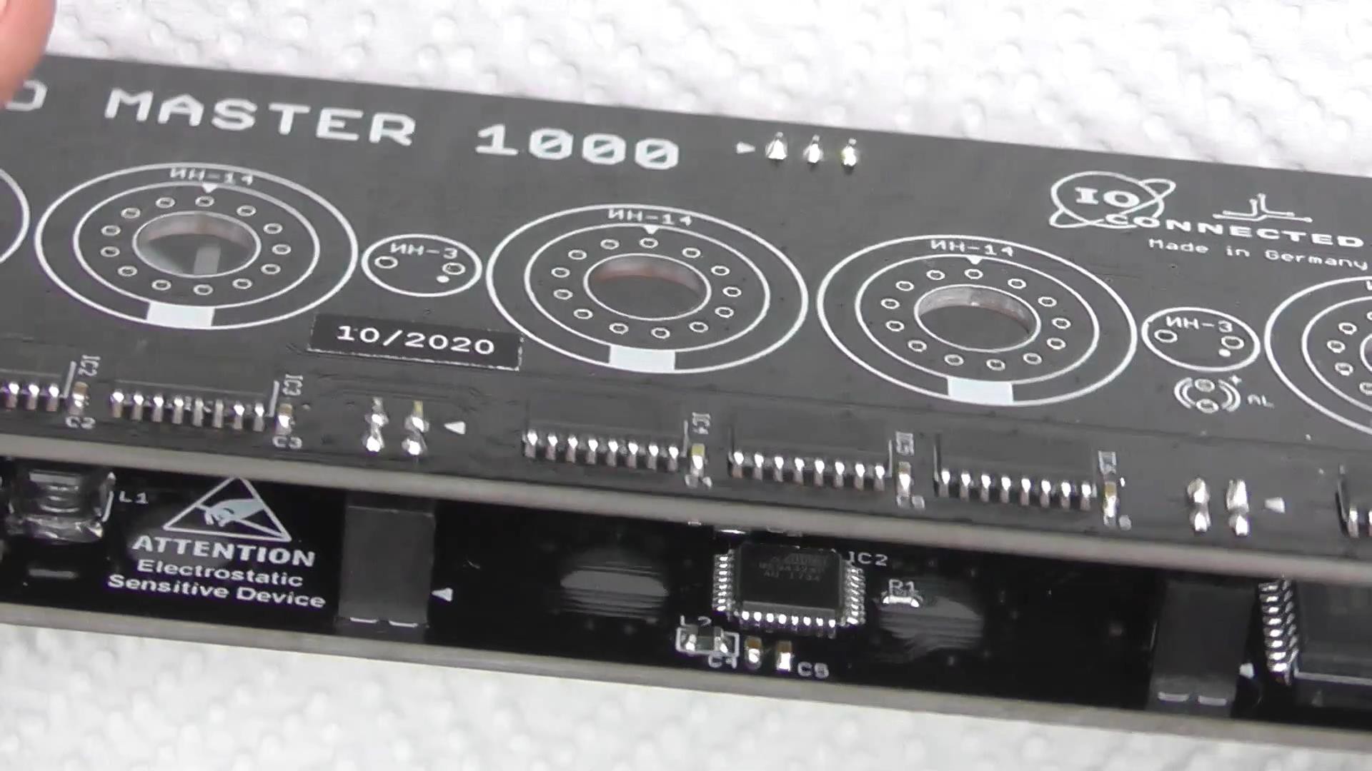
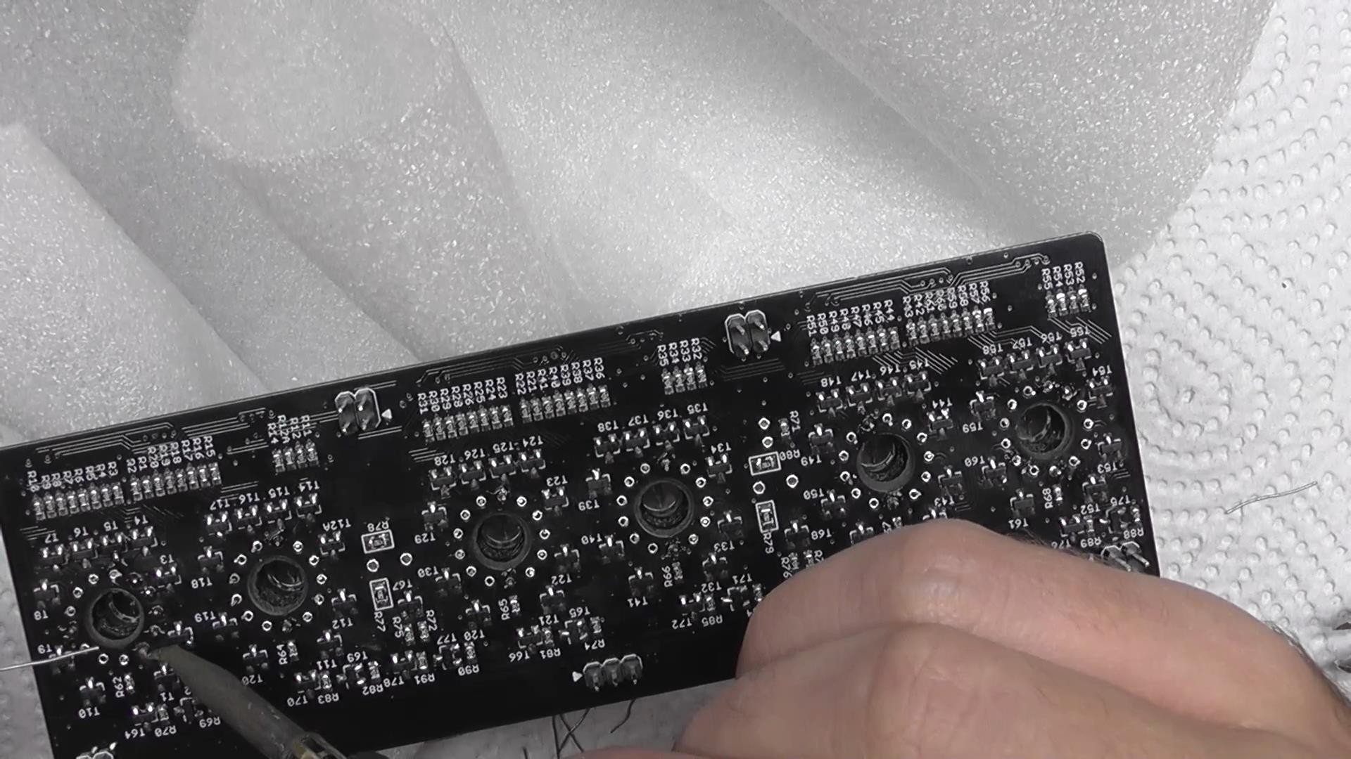
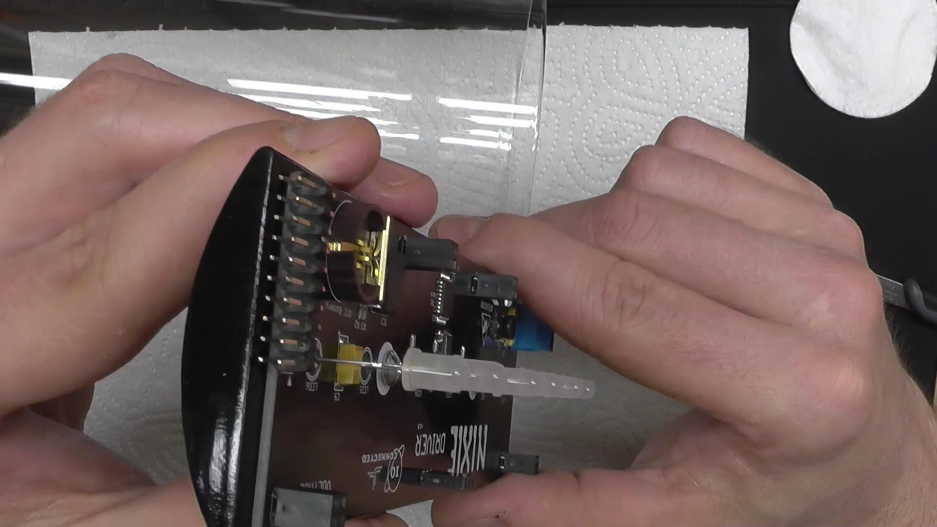
Everything is hand soldered. It was kinda obvious that using any "easier" method would've not been dignified for this project. Here's a close up of the nixie board. This is the bottom side and you can see the High Voltage transistors and .. a lot of 0603 resistors.
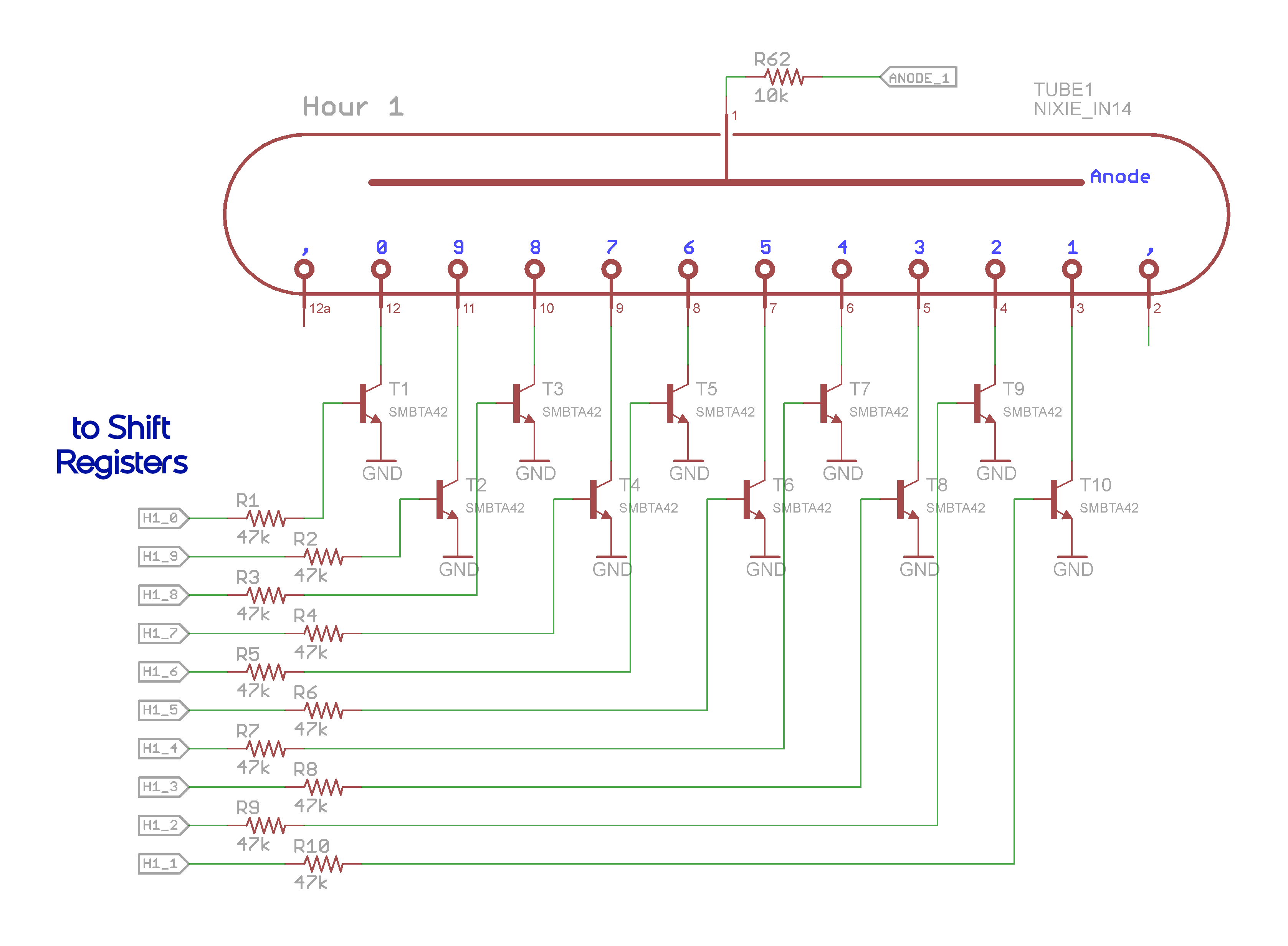
Here's how I drive each digit:
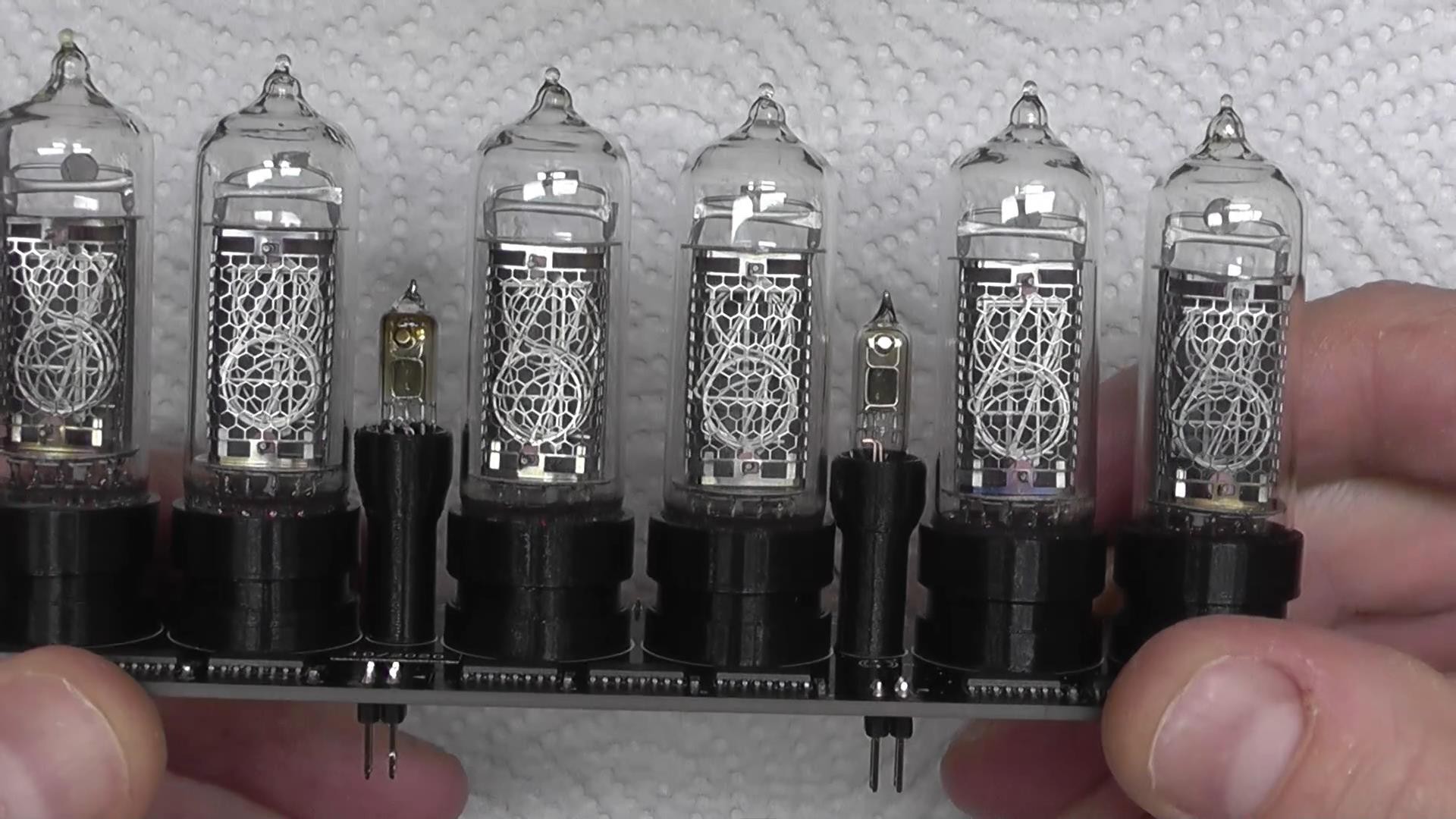
Each IN14 tube has 10 digits (0..9) and two separation points which I'm not using. Instead I used two IN3 tubes. The cathodes of each digit go to the collector of an NPN HV bipolar transistor. The emitter of each transistor is grounded. By polarizing one base at a time I "turn" on or off the desired digit.
The tubes are Common Anode and to control the brightness on each digit (PWM) I used the following circuit:
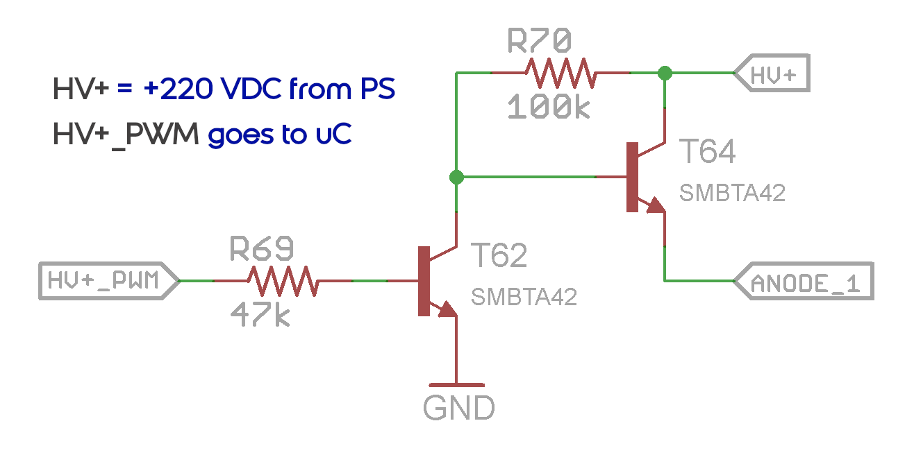
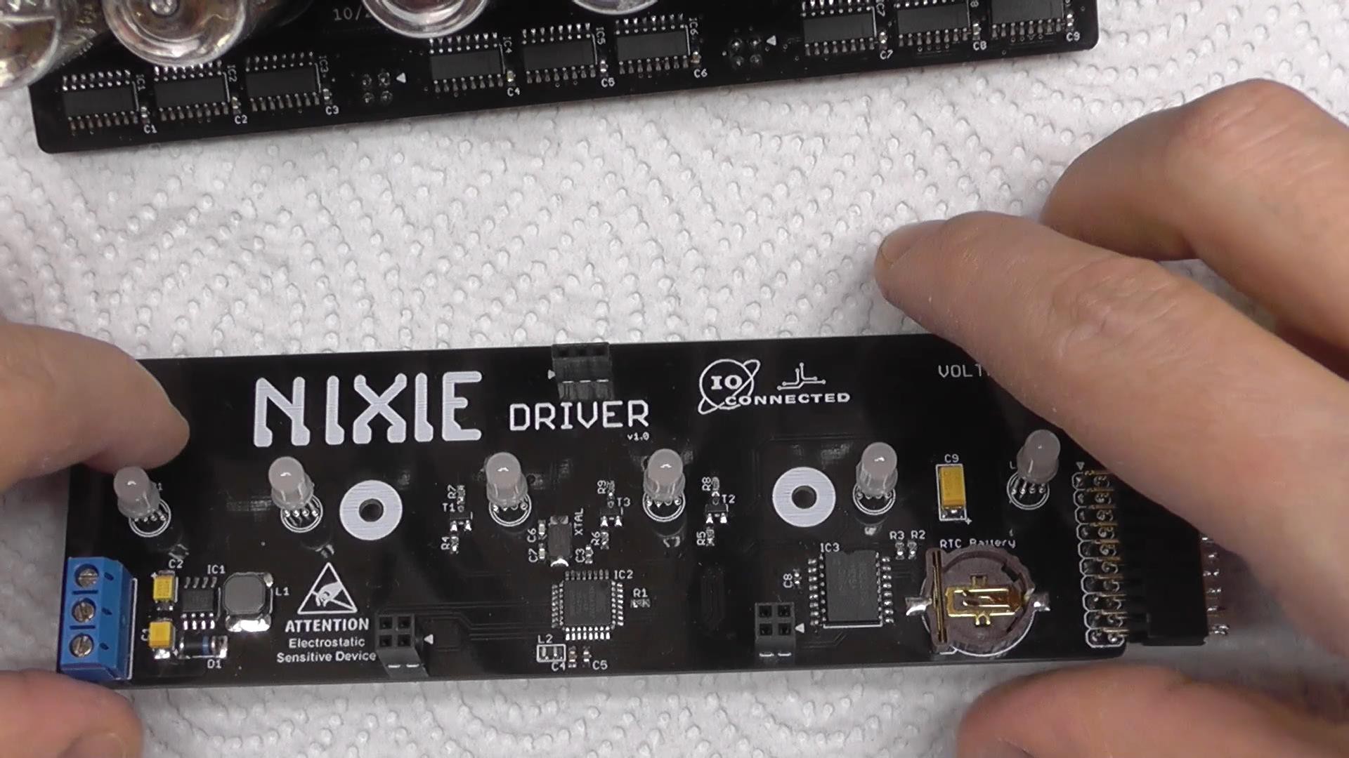
The Driver board has an 8bit AVR which does all the operations, speaks with an RTC chip over I2c, controls the ambient lighting, and communicates with 9 Shift Registers over SPI. These shift registers are daisy chained and their outputs are driving the HV transistors for the cathodes. The pulse-width-modulation for each tube's anode are is done in software mode.
The next photos are from the top side of the Nixie board is where the tubes will be sitting. I was soldering the shift registers.
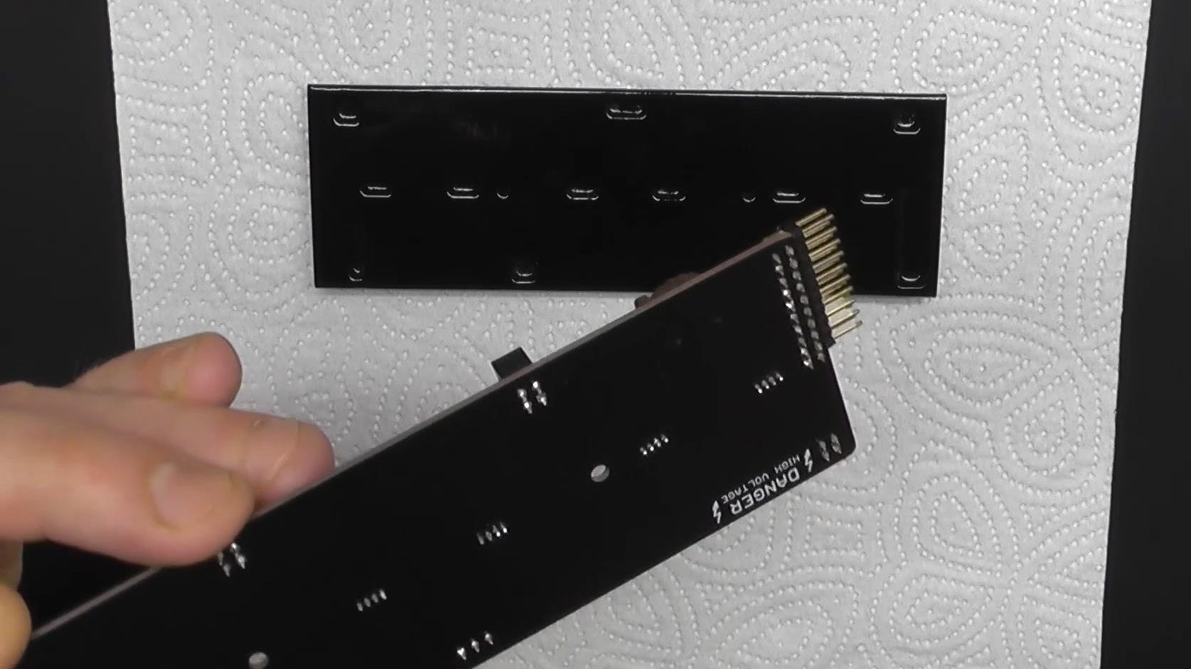
And here's the driver board:
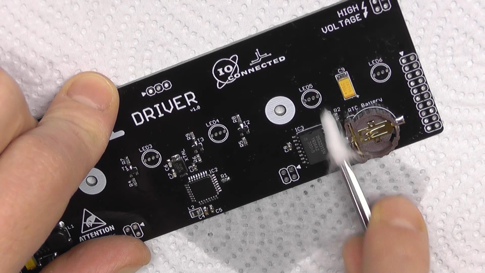
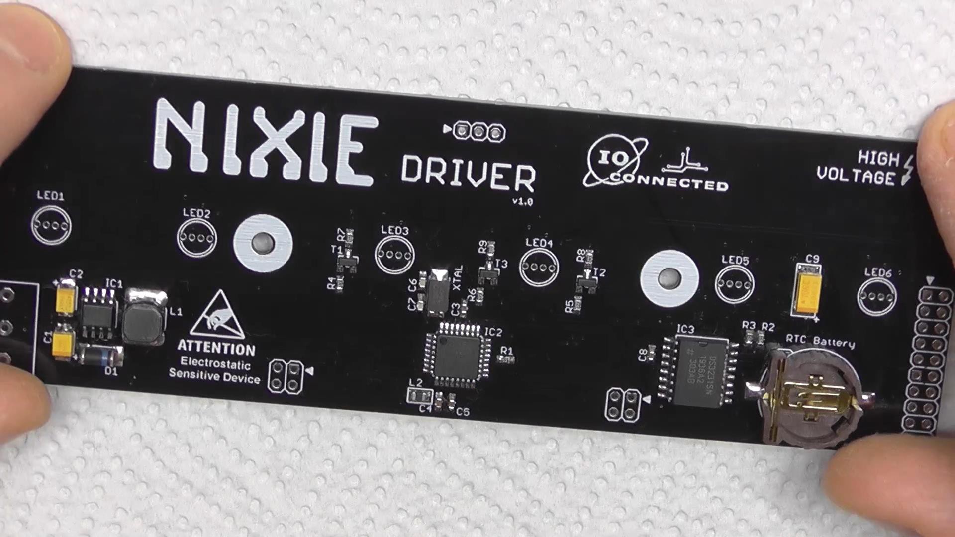
The driver sits underneath the Nixie board. The 2 boards are connected through 5 x 2.54 Headers.
These are the sockets I modeled and 3D printed for the nixie tubes:
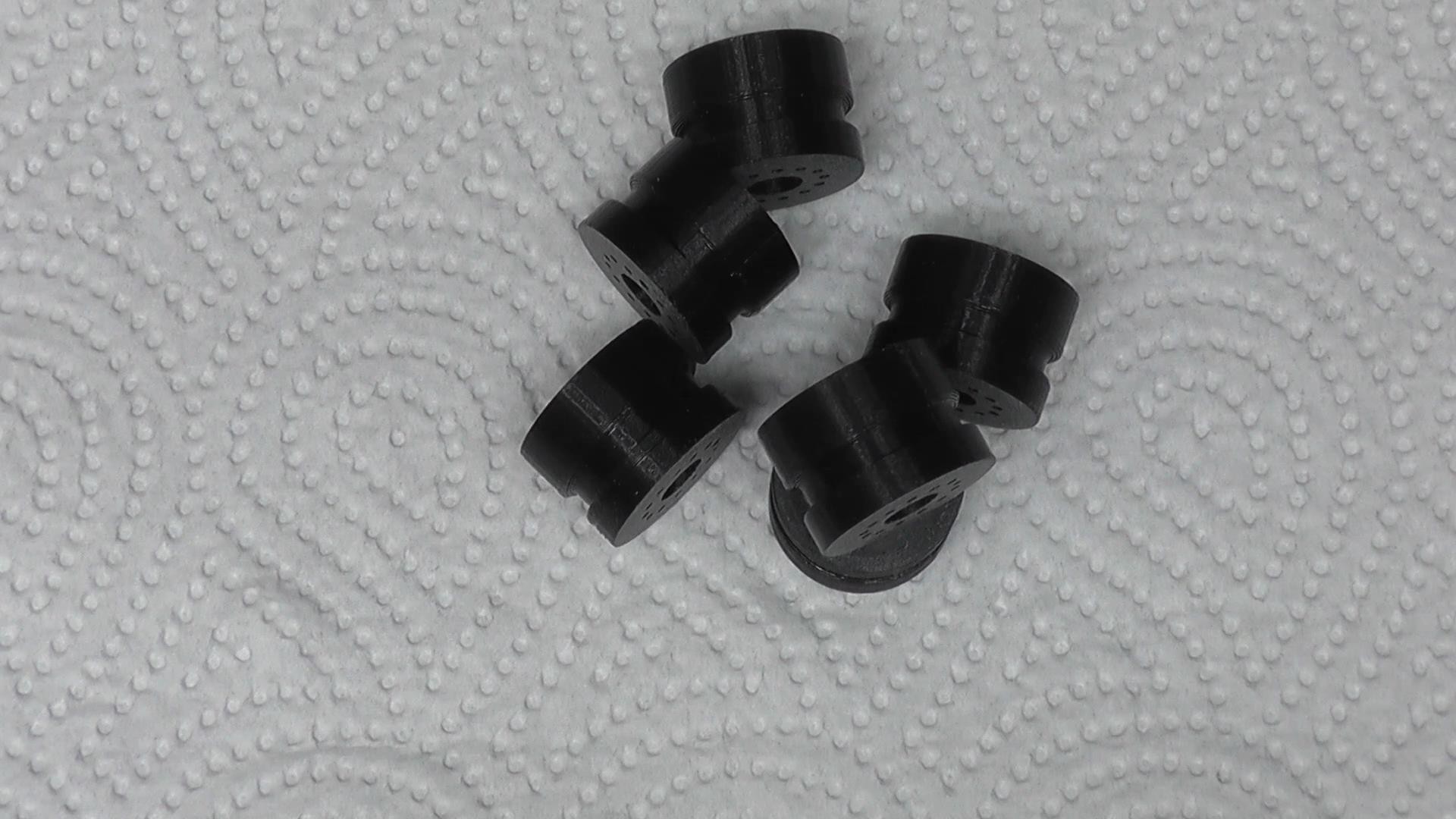
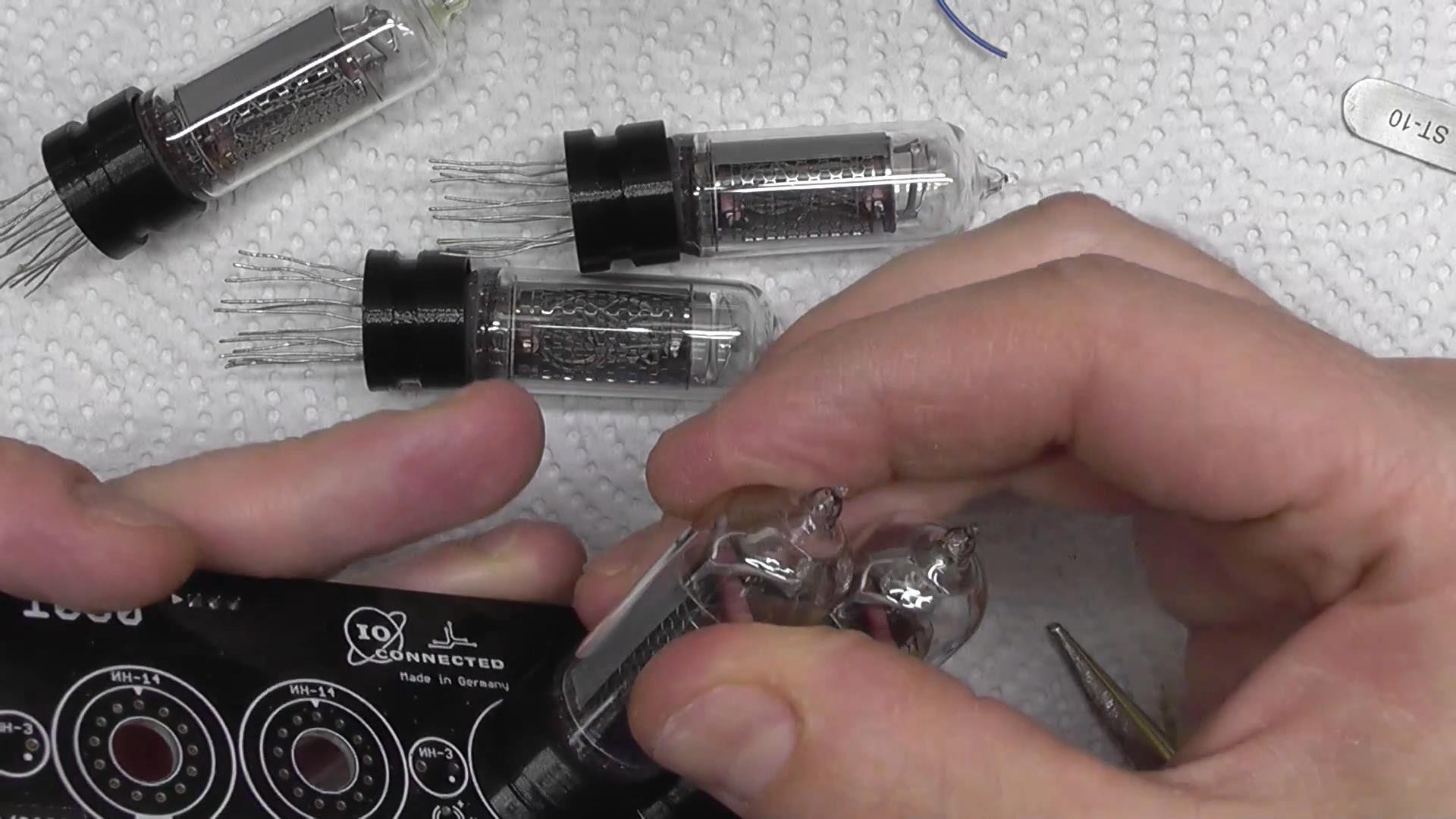
One of the IN3 tubes has a slightly yellowish stain. I like it, cause it gives a little "worn out" feeling.
The next photo shows the RGB LEDs on the driver board. They go through holes on the Nixie PCB and and fit into the socket. The light will only come out from beneath the tubes.
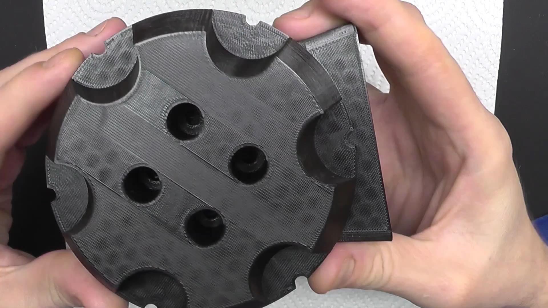
The driver board "sits" on a 3D printed part which isolates the whole thing from the surrounding metal grid.
After several tries to print the parts for the case, I had to replace the extruder nozzle on my printer.
It took a while to print and clean all the parts.
I then sanded, deburred, painted and glued the parts which were too big to print at once.
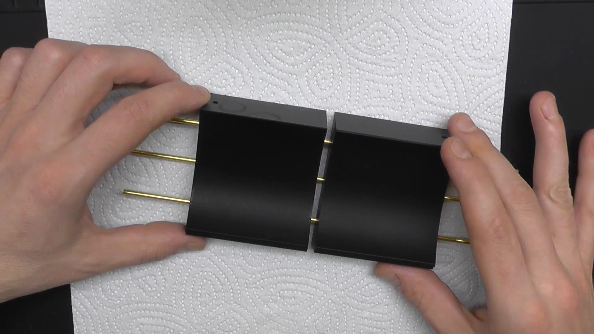
The lateral caps have a lot of wires running through. I made inner channels for all these wires so they won't be visible on the finished product.
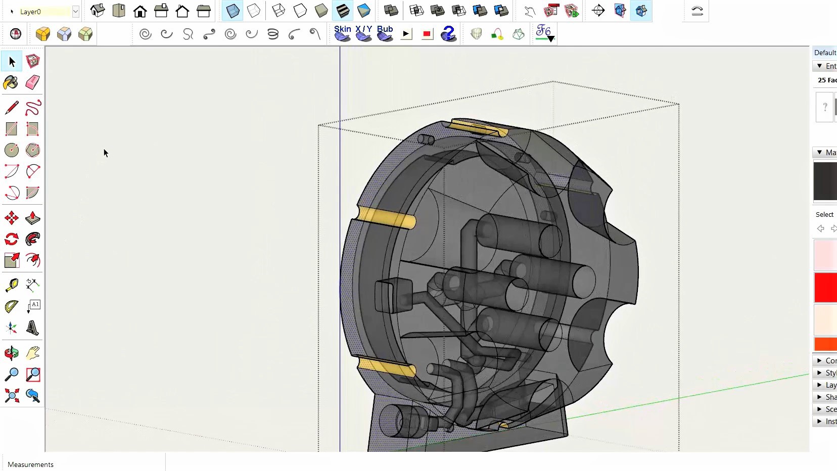
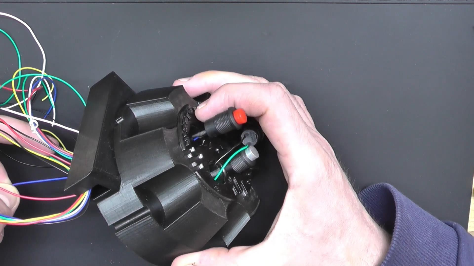
To pull each group of wires I used masking tape to cover all the other channels leaving only the current holes exposed. Then I inserted a textile thread with a small cotton ball and used a vacuum cleaner on the other side of the wire channel to "pull" the cotton ball through the channel. Then I used the thread to pull the wires and repeated the same procedure till I got all the wires through. There are 4 buttons on the right Cap which I use for manual control. There's also an IR receiver for remote controlling, a small piezo speaker, and the ISP header to flash the firmware on the microcontroller. This was a long and frustrating process.
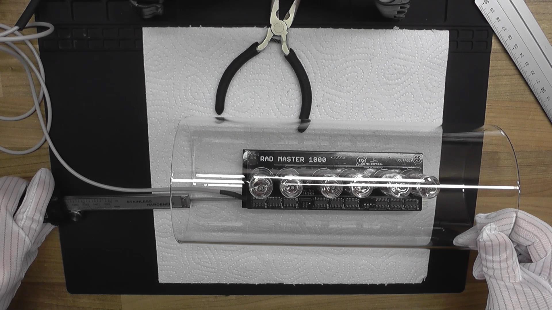
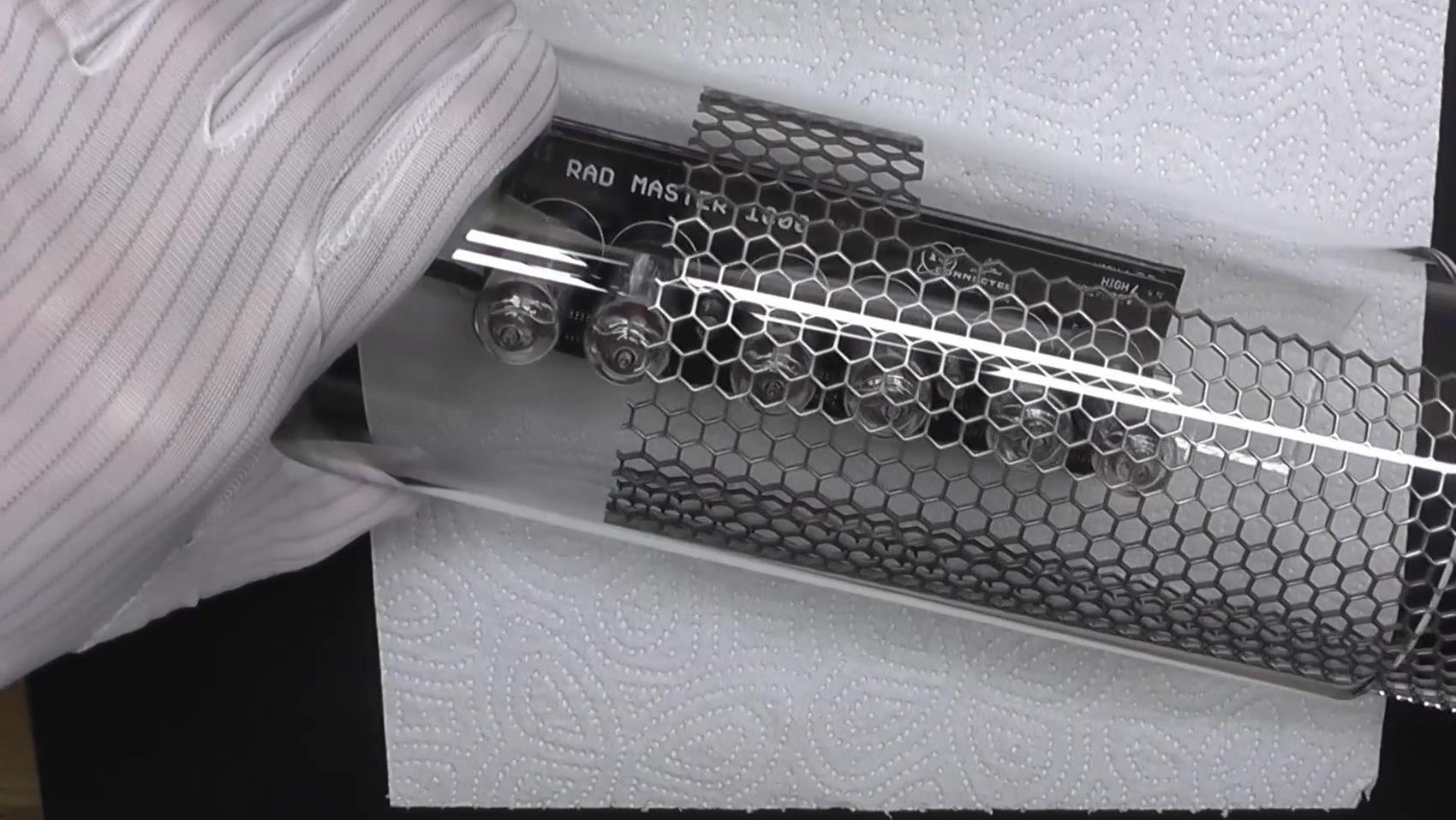
After inserting the electronics inside the glass cylinder I made a formed the surrounding metal grid. It's cutout will accommodate the boards sitting on the printed pad.
The glass cylinder sits on it's own pad which was made out of two separate parts.
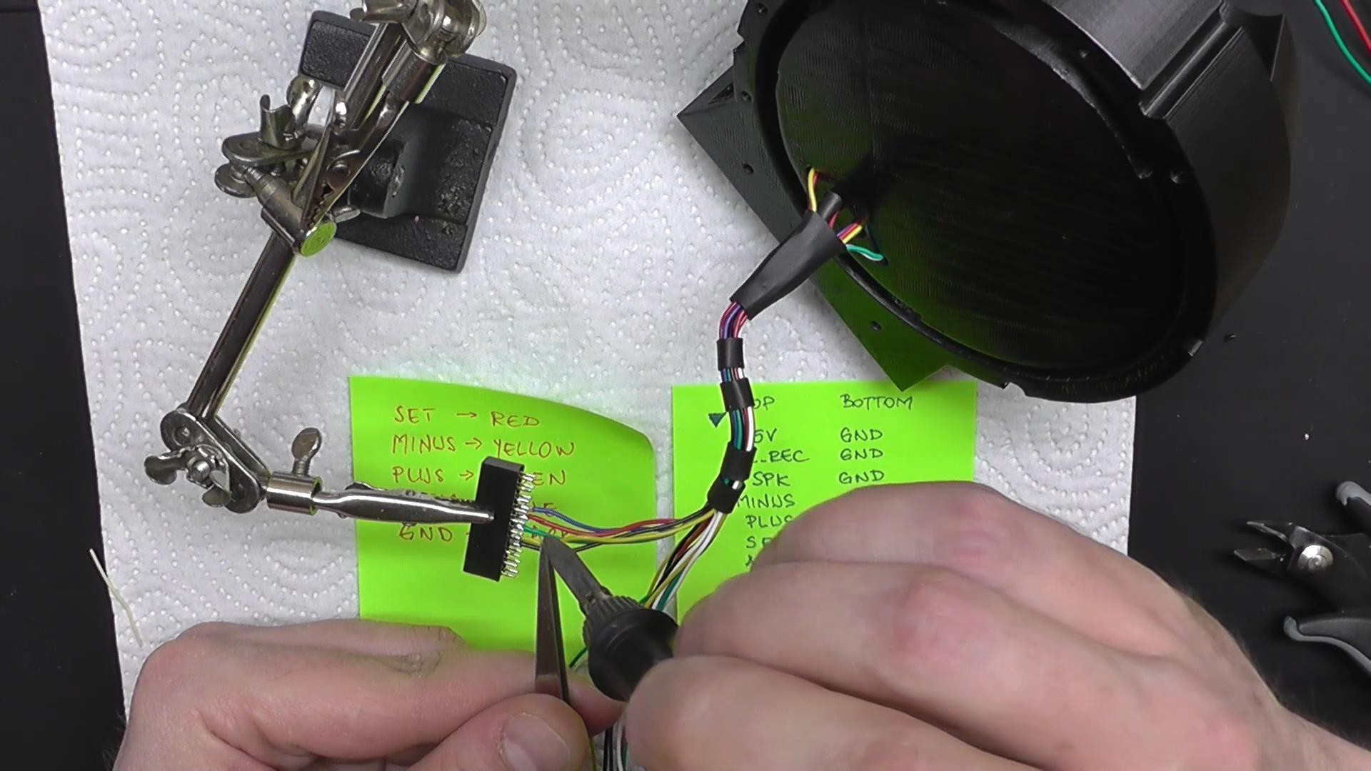
The end of the wires are soldered on a "custom" connector with 3D printed case. I then marked the first pin and inserted the connector in the male header, present on the Driver's board.
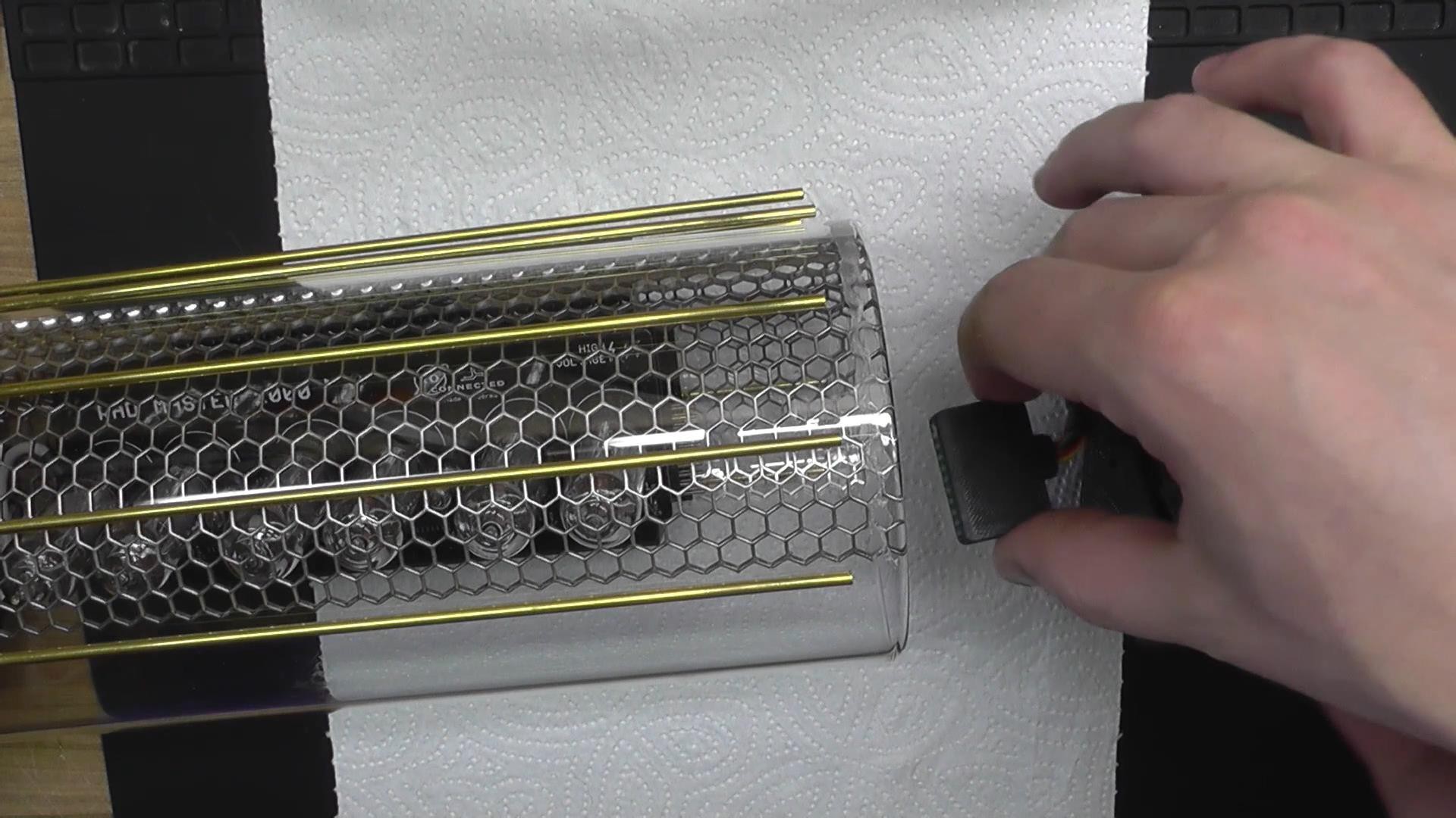
The brass rods have the same color I used for the logo and the markings on the case. I think it complements the black and silver.
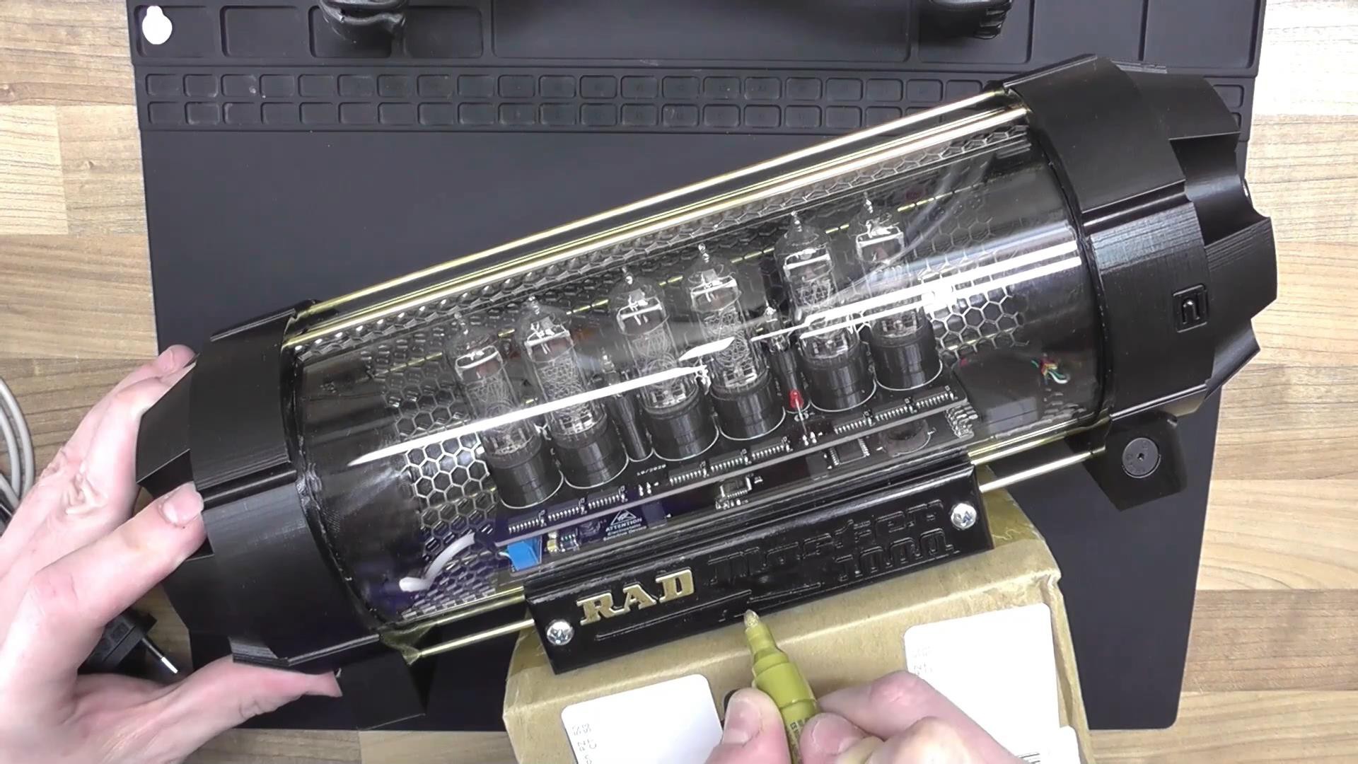
Finally, applying power for the first time and flashing the firmware.
My lab assistant Mika, was anxious to test it. As soon as I went out for 2 mins she took control of the whole operation
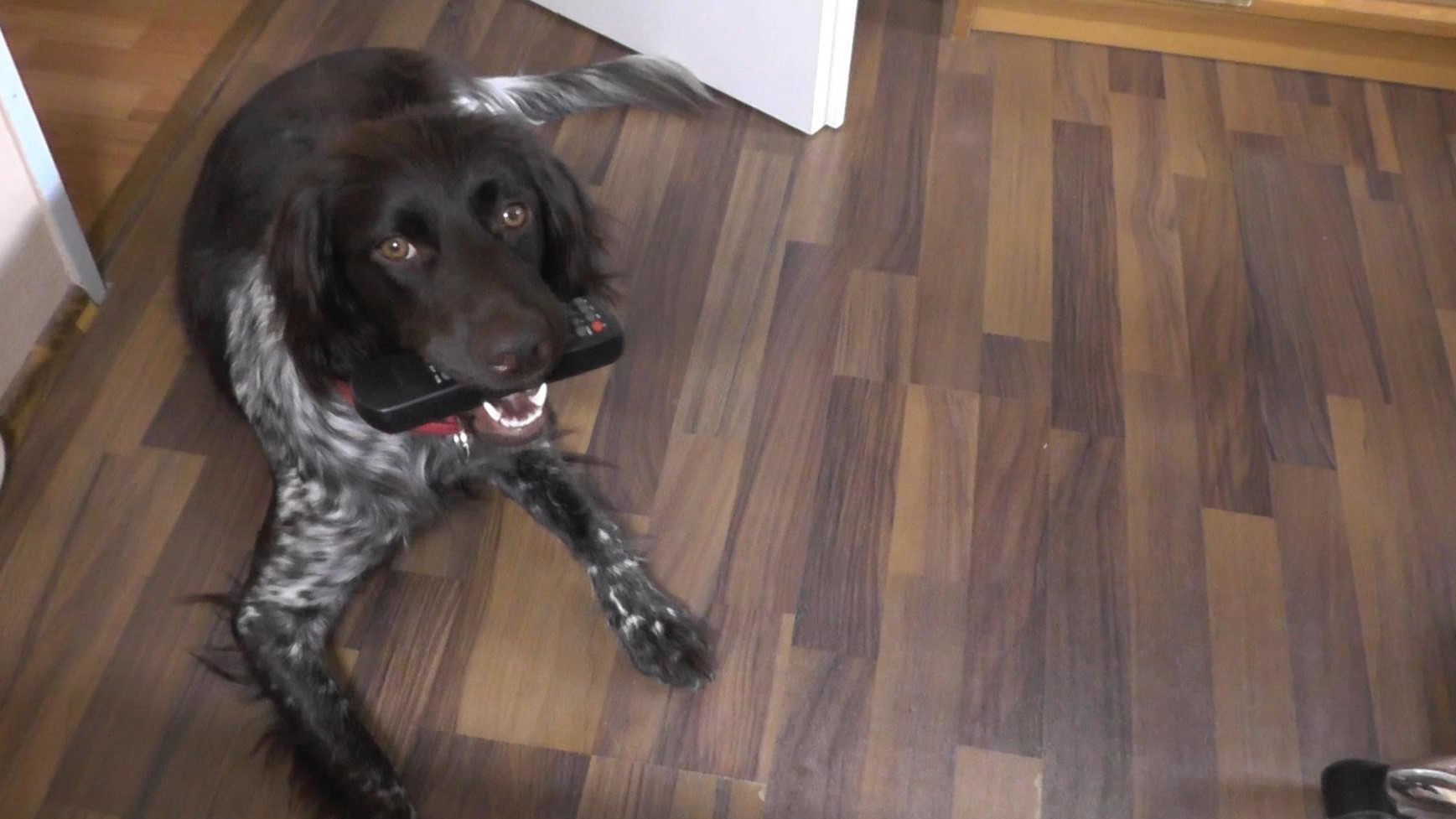 I think she loved this particular project. She digs everything involving lights and shadows :)
I skipped a lot of steps here. You can watch the whole building and assembly process on my Youtube channel:
I think she loved this particular project. She digs everything involving lights and shadows :)
I skipped a lot of steps here. You can watch the whole building and assembly process on my Youtube channel:Epilogue - "that thing's glowing in the dark"
It was supposed to be a Christmas present. I wasn't able to finish it in time.
It took me almost 6 months from the moment I placed the first order and started to sketch the concept, till I applied power for the first time.
Is it perfect ? Well.. probably not.
I know I could do much better next time. So many things were "a first" in this project. So many things could've gone wrong. I drew footprints for parts I didn't have, and sent the PCBs to manufacturing before I actually got the parts. Sometimes all the passion and the work in this world are not enough. You still need a bit of luck. Those of you who spent nights debugging an odd thing, looking for the cause of a failure when everything looks spotless, and then magically getting it to work, know what I'm talking about. This project went smooth from the beginning till the end.
I would make it better not because I would work harder or because I would put more time and passion. But because I learnt so many things. Things that there, sometimes buried deep, waiting to be discovered. Techniques that you develop by trying to find the best way to do it. Things that you can't find in books or in a fancy seminar were you are told .. just make it work.
So yeah.. if you have the time and the motivation, it is worth it to shoot for perfection, to stretch the limits, to find an extra 1% after you already gave everything you have.
In the end.. it's your ride. Something nobody can ever take from you.
"for what it's worth it was worth all the time" - Green Day
PS.
My father is still speechless.