* First portable computer with TFT/color active matrix screen according to Z*NET International Atari Online Magazine (#91-13, vol. 7, no. 13, April 5, 1991) and Toshiba TEG October 2002, Art. No. CBB2B 10/02E, pp. 4.
Introduction
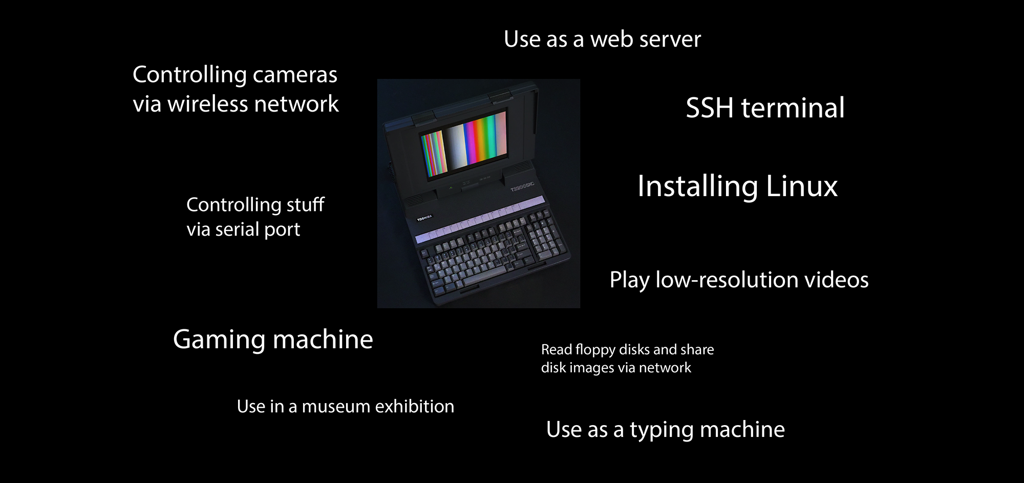
I made a quick overview of the work that has been done in this videos (I plan to prepare more videos on the details):
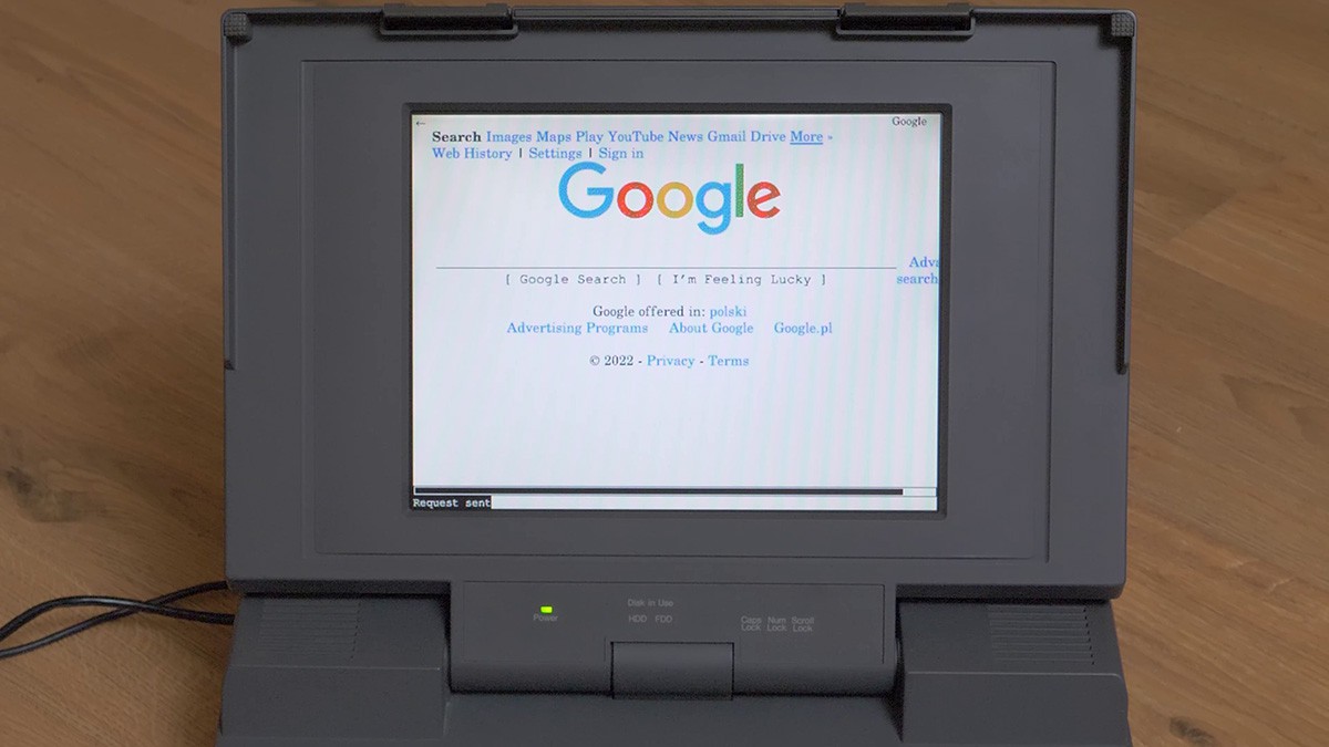
Toshiba T3200SXC is probably the first (1991) portable computer with a "modern" color LCD screen, a TFT one. Therefore it is a significant piece of computer history. It also has ISA expansion slots, which give some endless opportunities for the expandability. Unfortunately, this unit had faulty screen and power supply. I described the original state of the machine in this project log post.
The challenge
The goal of this project is to repair this machine and make necessary enhancements (albeit possibly non-destructive ones) to keep it usable in 2022 and forseeable future. That does not mean turning it into a viable daily-driver PC, but rather restoring its original functionality and enhancing user-frendliness, so it can serve as a functional, portable, all-in-one and fun-to-use example of early 90s digital culture heritage.
What to do
With that being said, the restoration/repair objectives are:
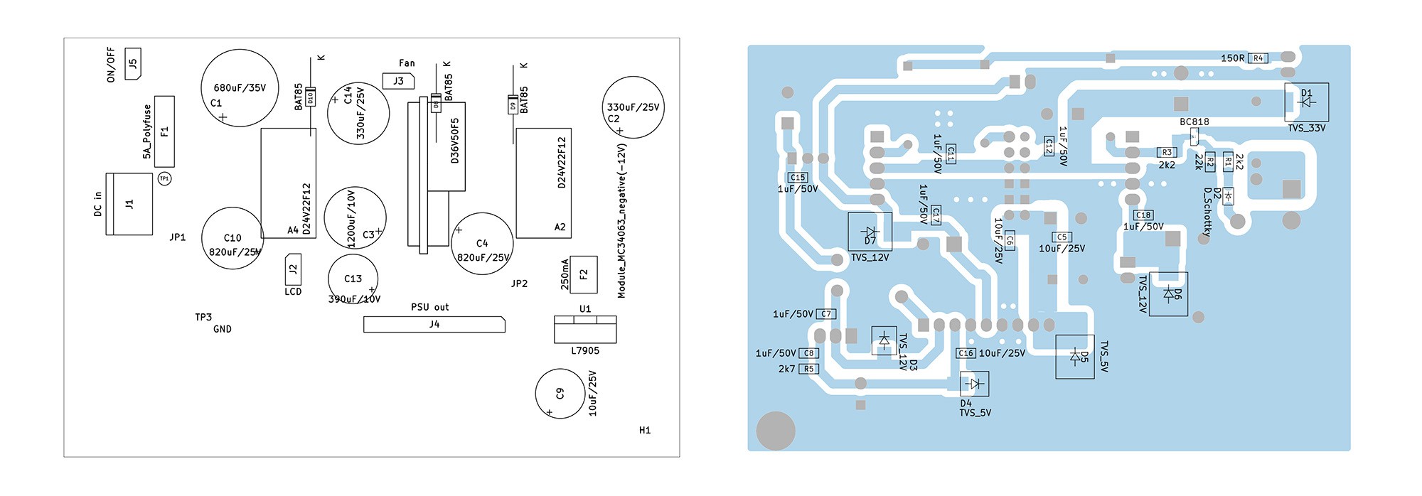
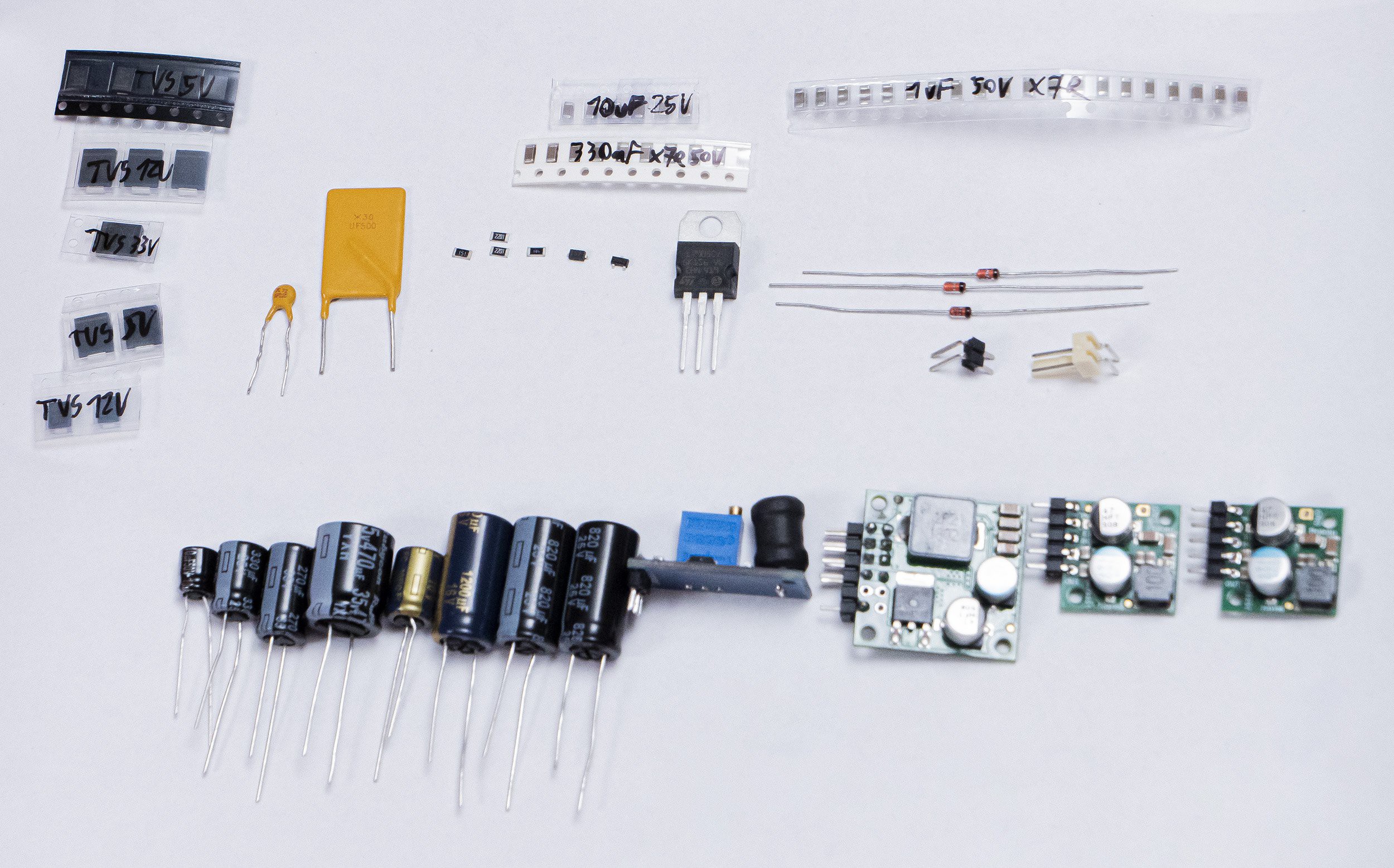
- Create a replacement for the broken power supply [working prototype has already been made]
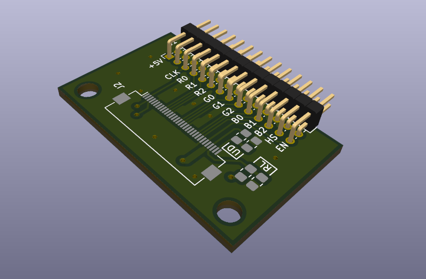
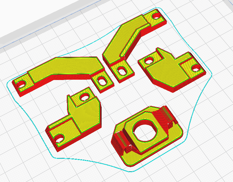
- Replace the broken LCD screen with one that would be indistinguishable from the outside, and would have the same resolution [a prototype of necessary converter and 3D-printable mount adapters were already made]
Because the prototypes have already been made with basic home fabrication methods, the additional goal is to tidy-up the design files, fix possible issues and publish them so they can be used with other machines, or even adapted to other types of machines.
The enhancement objectives are:
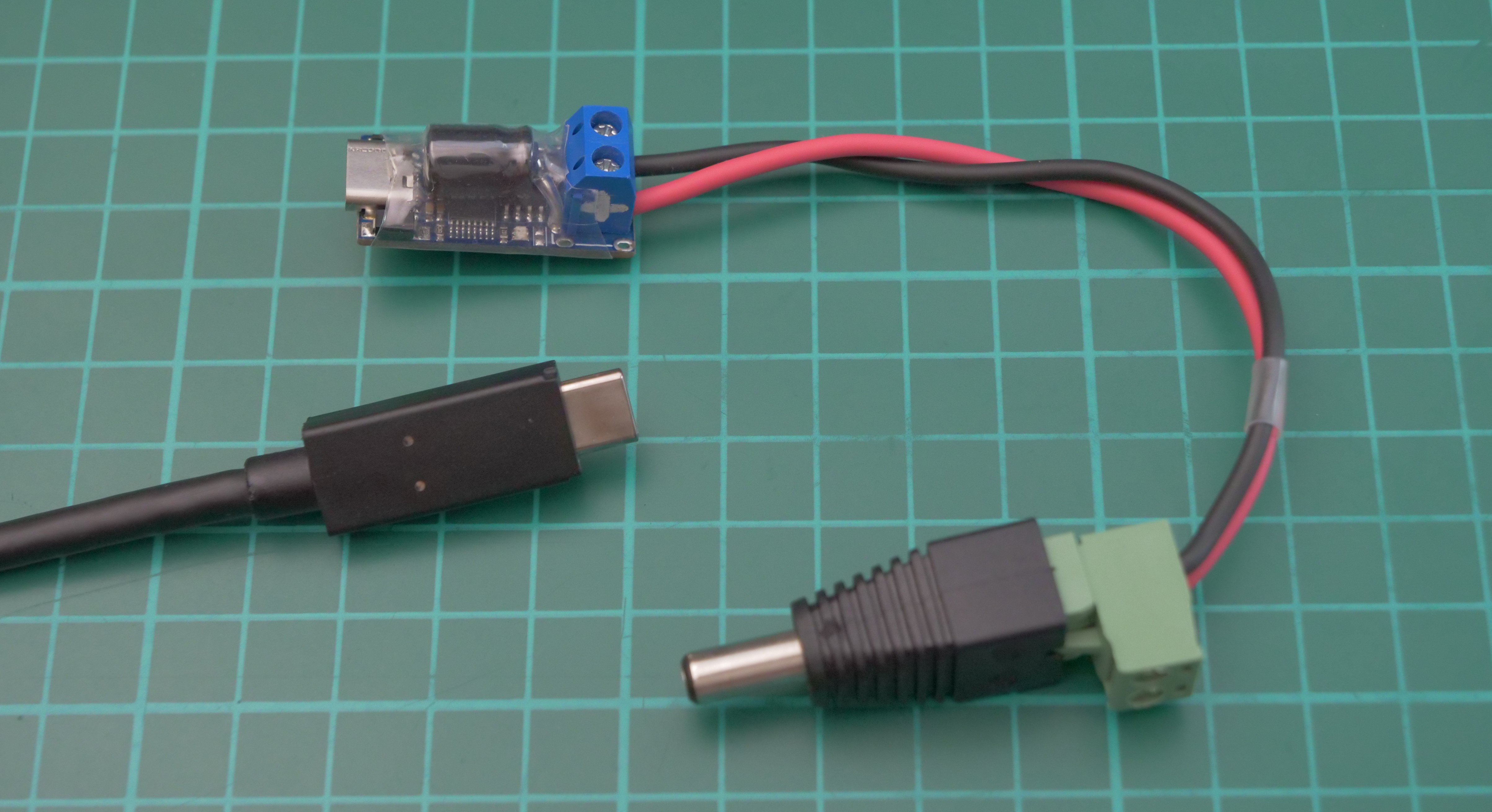
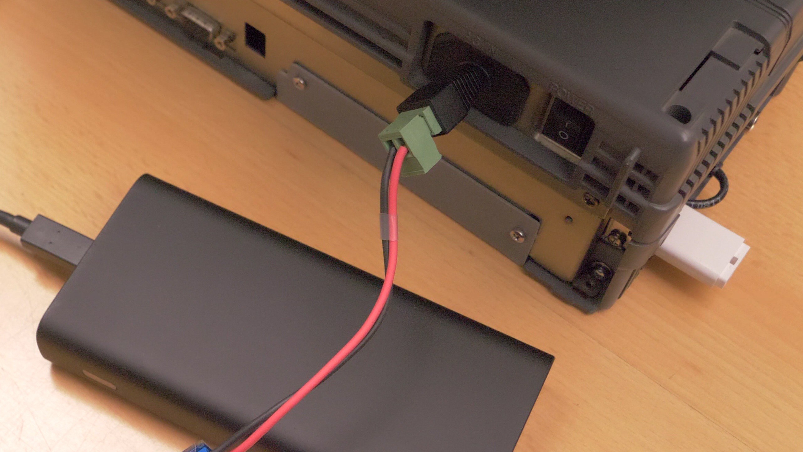
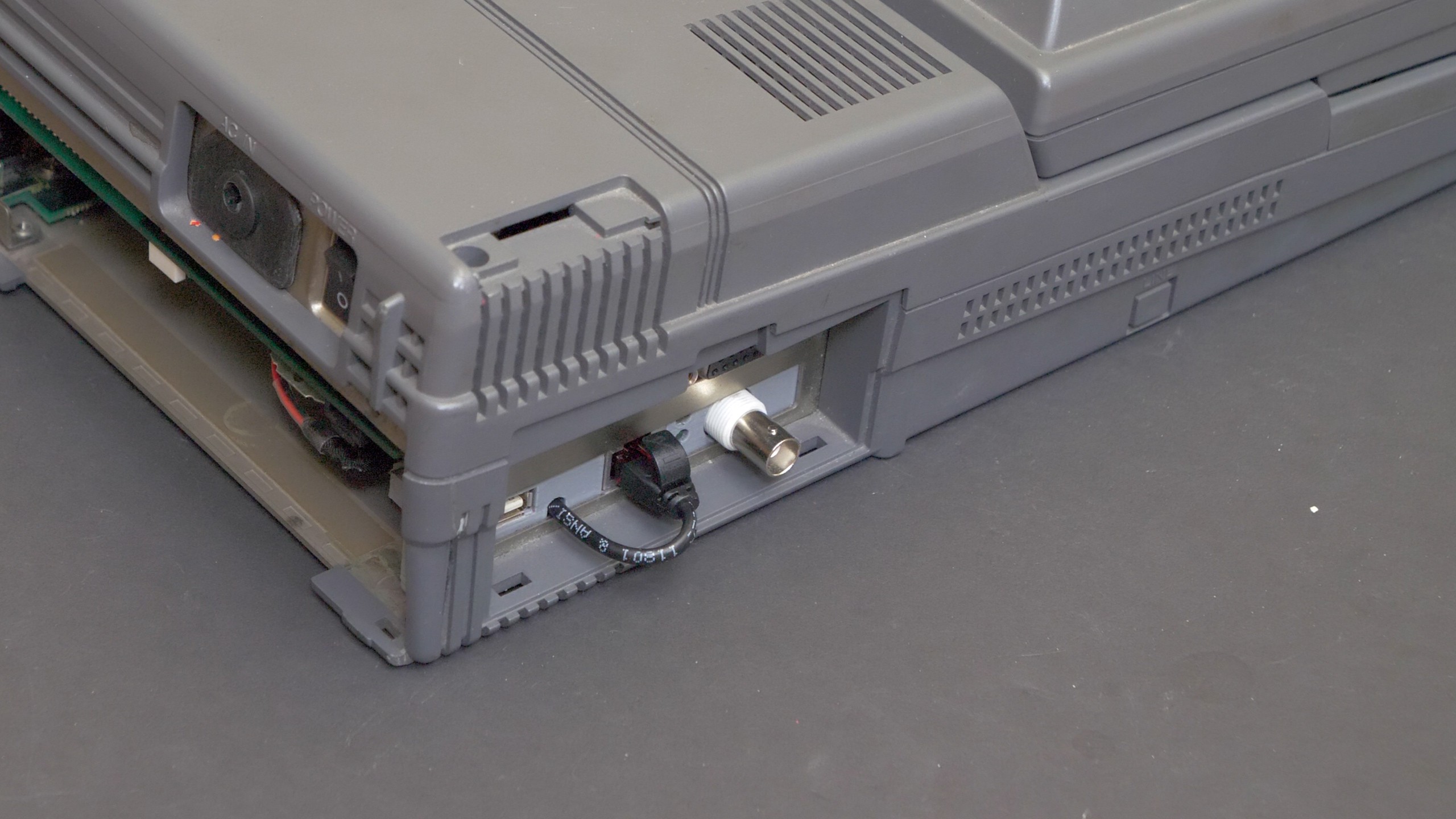
- Allow the computer to be battery operated [done by a USB-C PD to DC jack adapter]
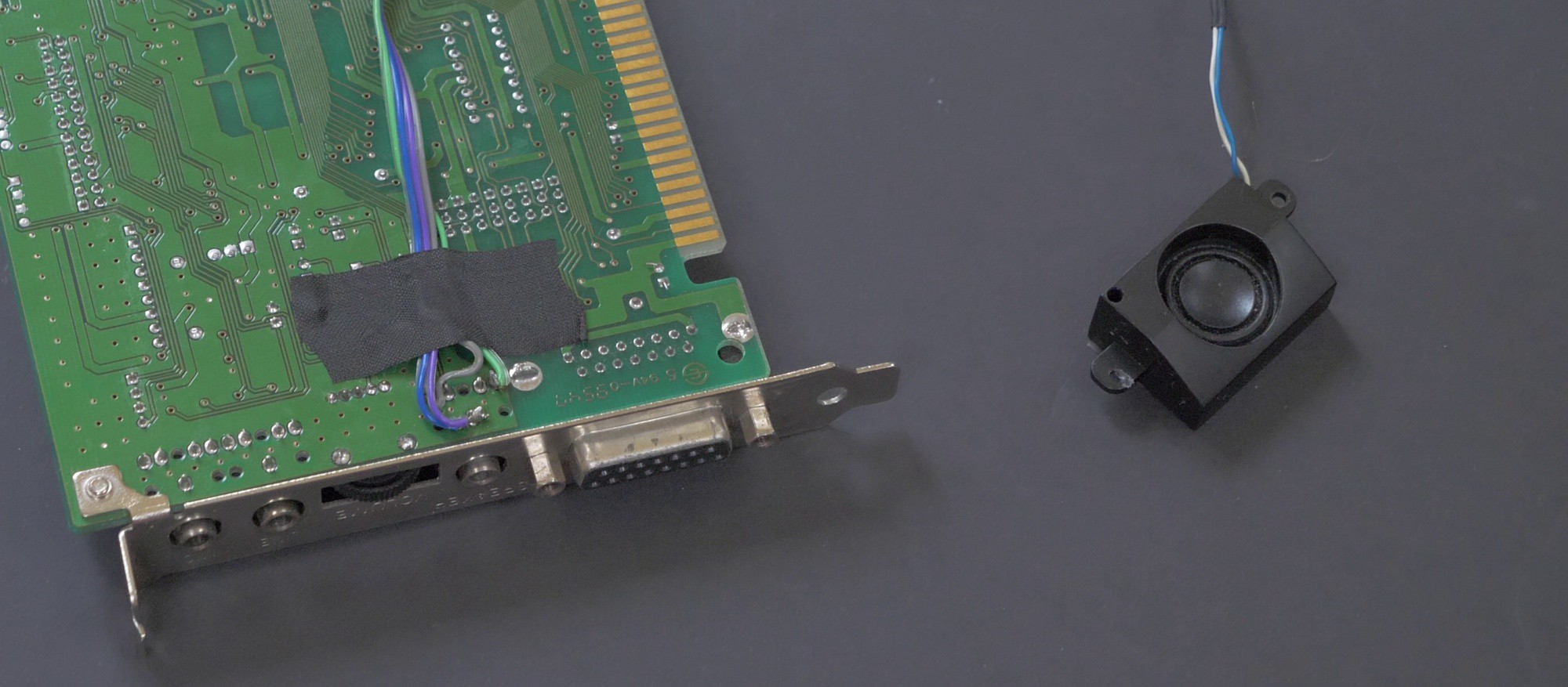
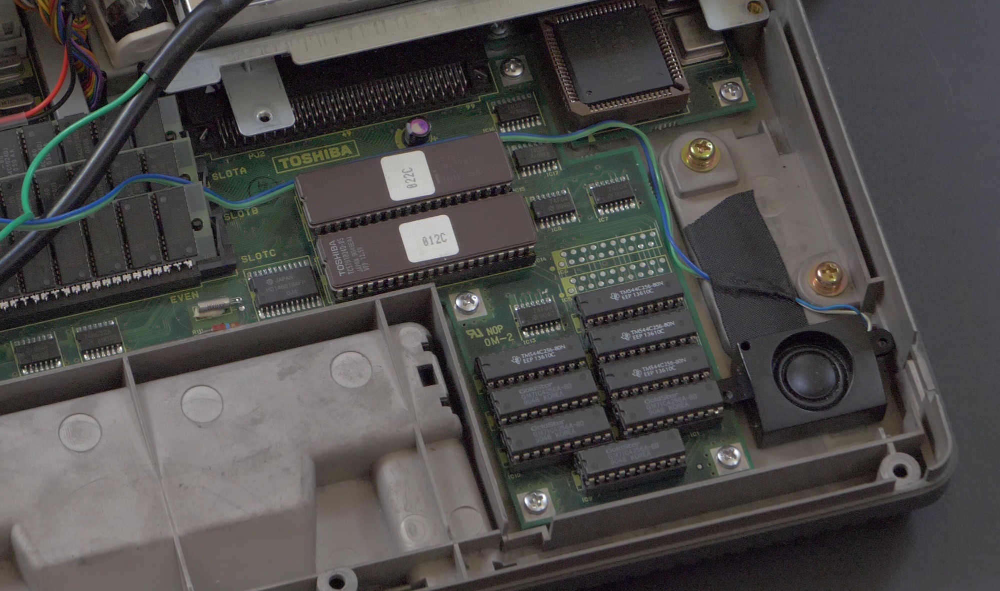
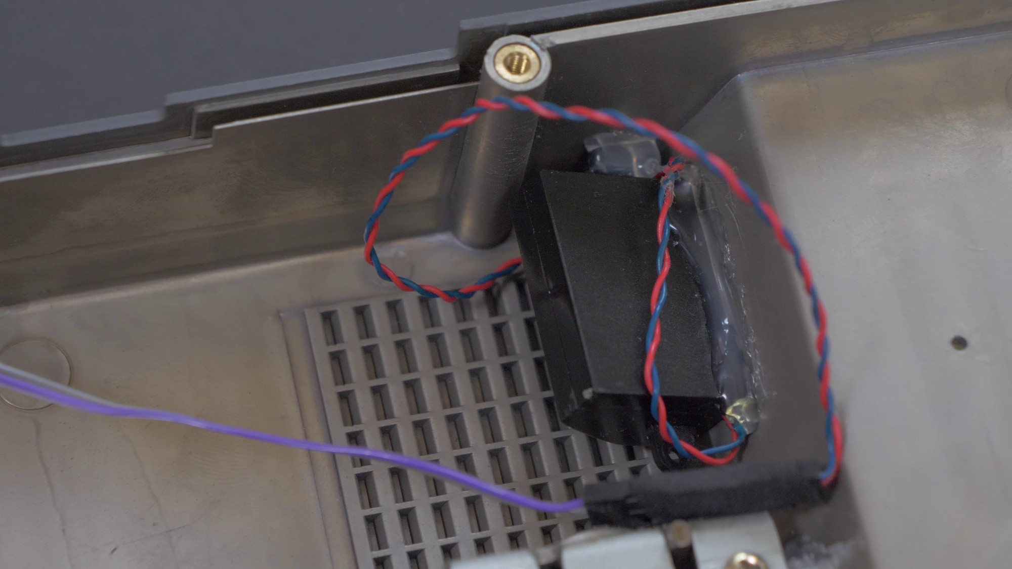
- Add internal speakers and sound card [done with ISA expansion card and speakers recycled from another laptop]
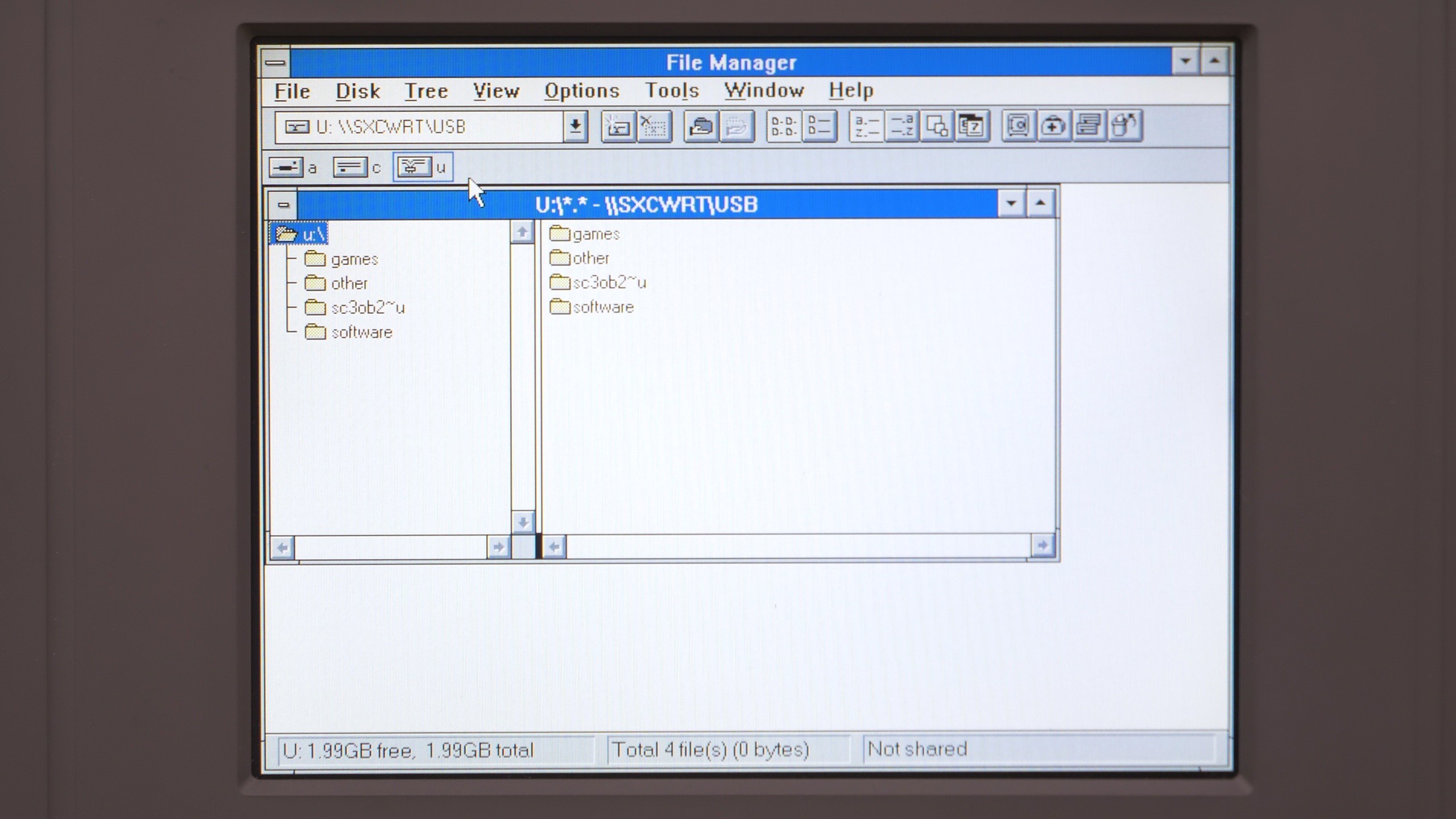
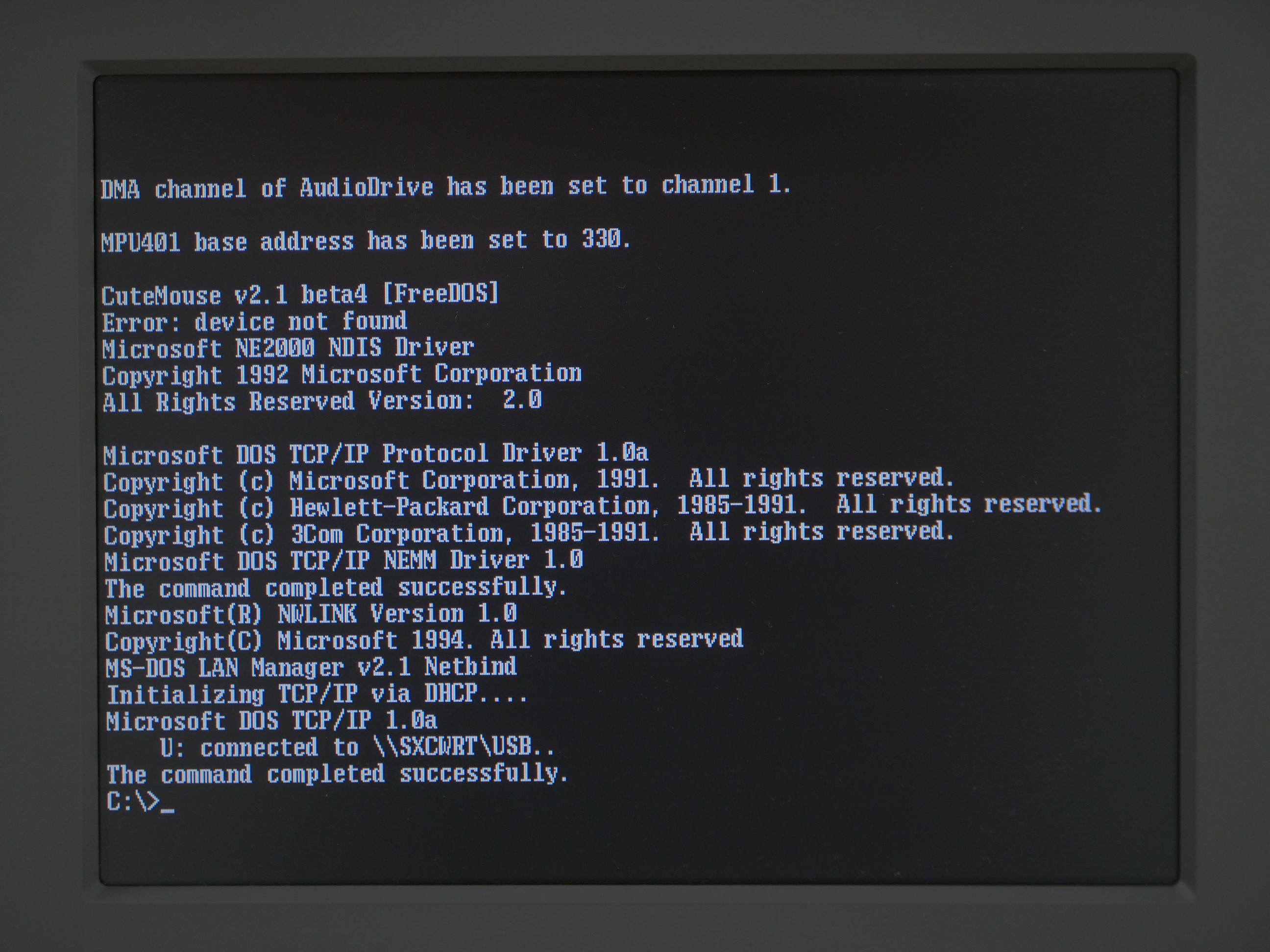
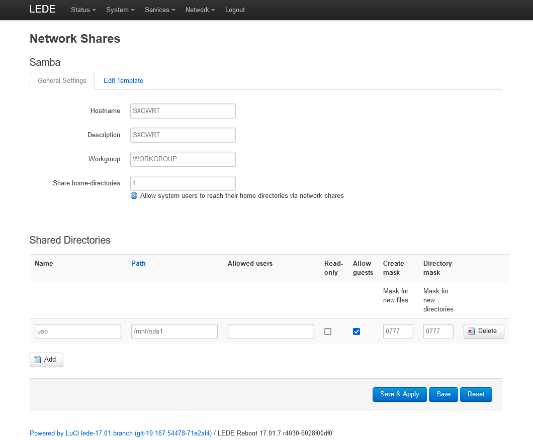
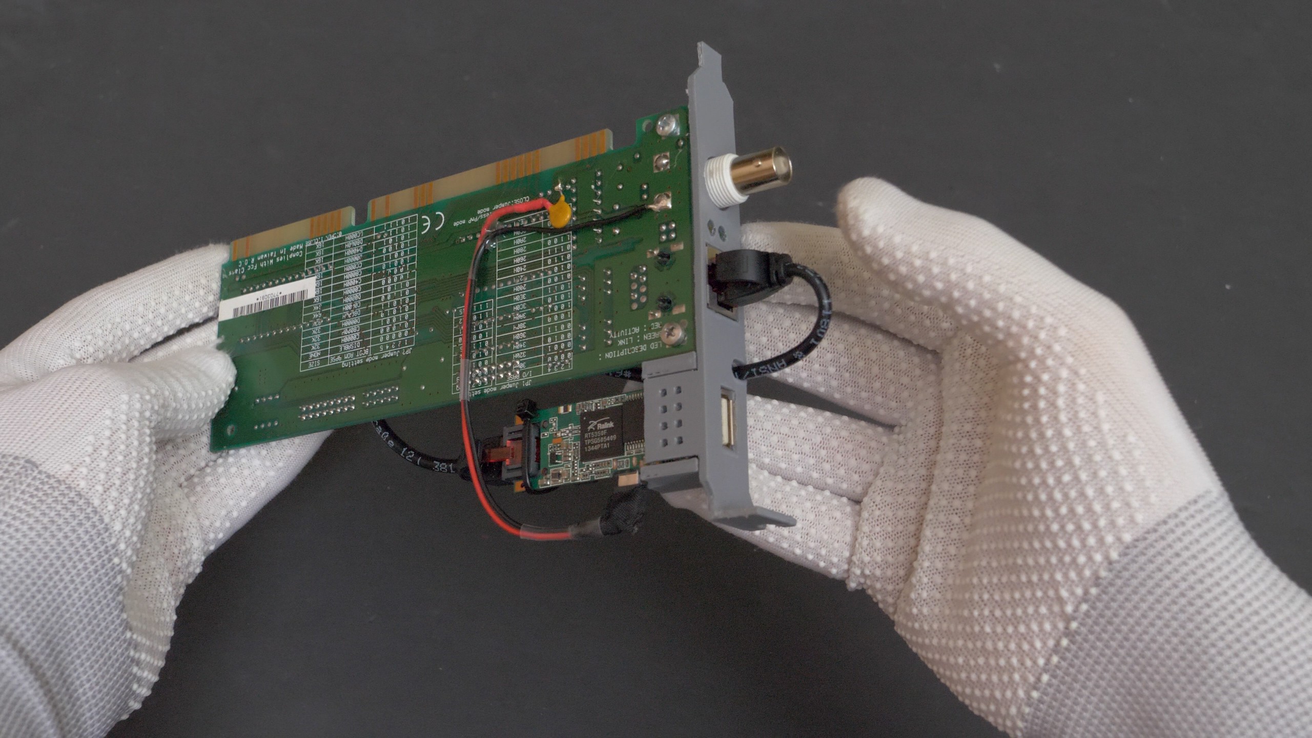
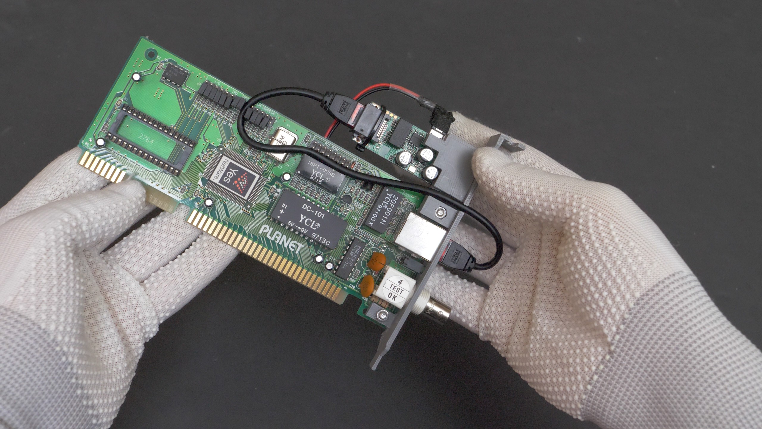
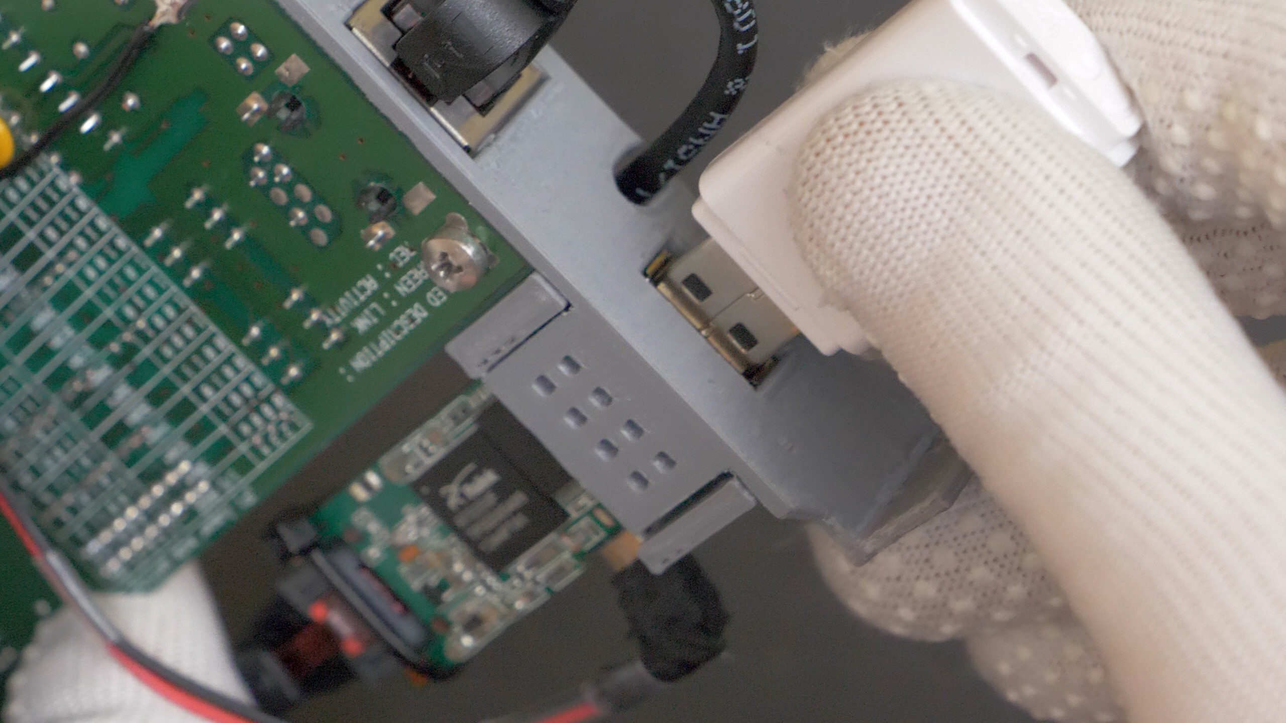
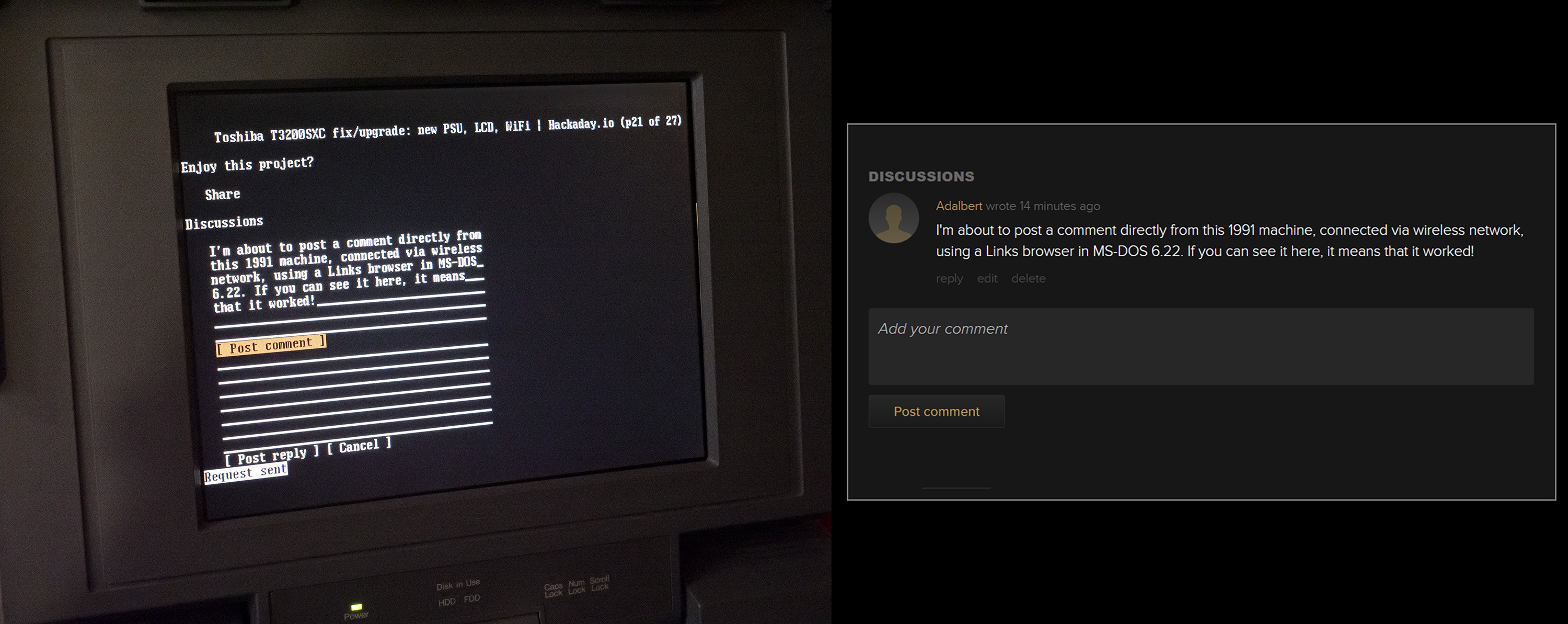
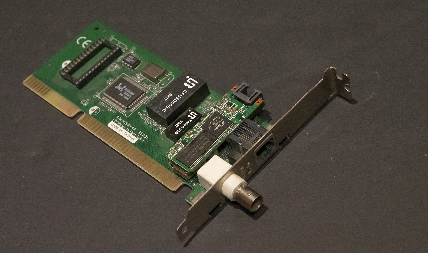
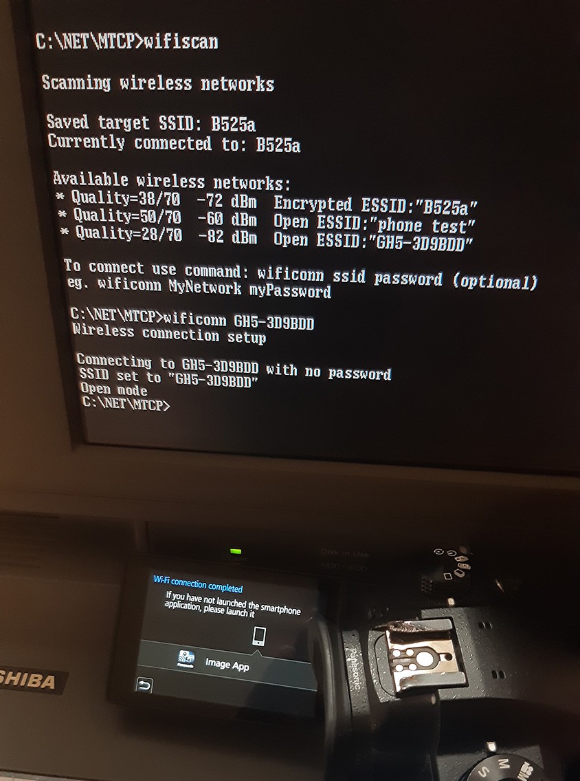
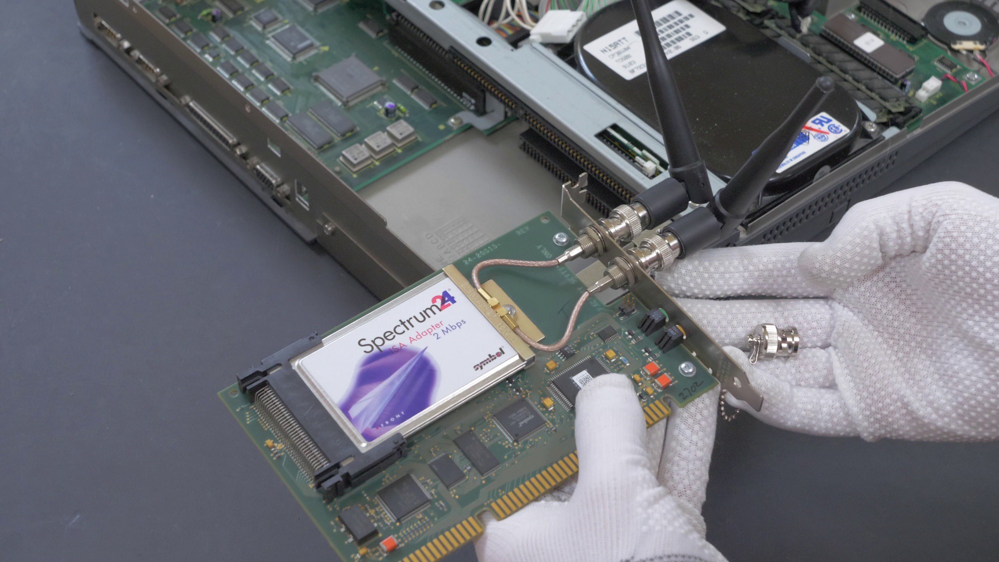
- Add easy-to-use wireless network connectivity, to make file transfer and accessing web easier [prototype stage, using embedded OpenWRT router, automation scripts and ISA Ethernet card]
Constraints:
- keep the external form of the computer intact
- enhancements have to be stealth and must not interfere with the "retro look and feel" of the machine
- no modifications to the motherboard itself, only peripherals can be modified
Such constraints were chosen in order to prevent the machine from being enhanced "too much", that means no 4K screens or gutting the internals and completely replacing them with something else.
Fun part:
- try to check what is possible witch such an old machine, obviously besides playing retro games [in progress].
Some historical facts
The active-matrix color screen used in this machine was a big deal, because it had quick response times and wide viewing angles. Passive screens (DSTN), which were popular even up to late 90s, had massive ghosting issues (it could take few seconds to completely refresh the screen, and mouse cursor /if mouse was being used at all/, could be virtually invisible during motion) and were just generally bad (but much cheaper than TFT). The cost of Toshiba T3200SXC was a whopping $7,249 in 1991, and that's just for the base model with 1MB of RAM (PC Magazine June 25, 1991, pp. 44). Here we have 7MB!
It was also featured in Microsoft Excel 1992 video:
Funnily enough, this computer was never capable of being battery-operated, yet it was shown as such in this promotional video. I wonder if the film crew has also been using USB-C powerbank to power it on!
Project takeaways and further perspectives
Even though Toshiba T3200SXC is a rather rare machine, the accomplishments of this project should be adaptable in some way to other PC-type machines.
- Re-designed PSU has +5V, +12V, -5V, -12V power rails with an extra +12V2 rail for the LCD, which...

 and new, smaller power supply (bottom)")


 deantonious
 tiefpunkt
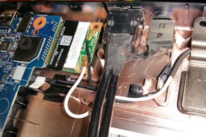
 controlmypad
 Marsupilami
Hello, i have old toshina T5100 notebook and screen (black/red) not working good, as i understand i can buy Toshiba LTM10C013 screen and not need any modification with cable. But i can't find how to buy this screen in google, aliexpress, ebay.. May be it have some analog?
I want replace original screen, but i don't know how to solder boards.
Thank you.