Start by removing the weight and making the chain into a loop.
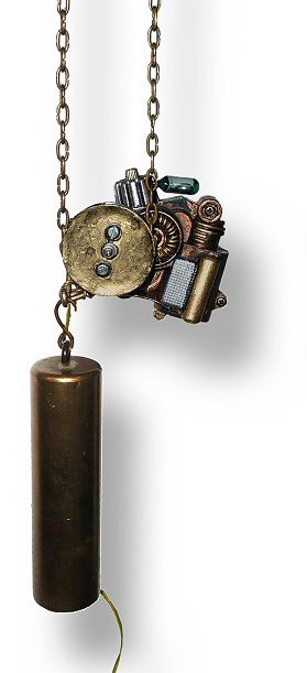
The P2-Winder sits at the bottom the the chain loop. The chain lies in a toothed chain-wheel. A motor and gearbox can turn the wheel.
The original clock weight hangs below the "taut" side of the looped chain. The Centre of Gravity (CoG) of the winder-plus-weight is slightly to the right of the taut chain. That means there's a little tension on the "loose" side of the chain to keep the chain wrapped around the chain wheel.
As the clock runs, the taut chain lengthens and the loose chain shortens. That action rotates the winder counterclockwise until the tilt-switch switches on; the motor turns the chain-wheel and the winder rotates clockwise. The total rotation of the winder is about 20 degrees.
The postion of the CoG of the weight-plus-winder is critical. The weight should be hung as closely as possible to the left side of the chain wheel: The total CoG should always be below and just to the right of where the taut chain meets the wheel.
The idea is that, as the winder rotates, the CoG doesn't move much to the left and right. That means that the tensions on the taut chain and the loose chain keep roughly the same values. It's not too critcal - the chain weighs 50g and the weight is 550g so, in the original arrangement of the clock, the torque at the clock's chain wheel varied by around 20% as it wound down.
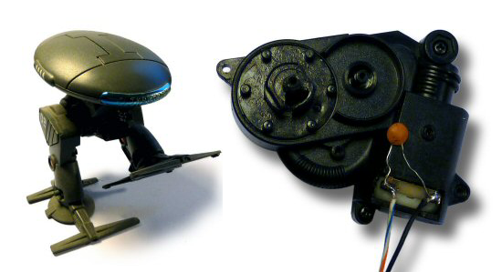
In theory, any low-power motor-plus-gearbox can be used. The essential requirements are that it should have enough torque (obviously) and that it should not be possible to back-drive it. I started with a commercial gear-motor which appeared good but, under some conditions,would back-drive. The current motor is from a toy and does not back-drive.
The chain wheel is made as a sandwich of different layers bolted together. It does not have to be very accurately made. I used steel of different thicknesses plus a little thin card as padding. The innermost layer has the teeth. The teeth must be long enough to engage the chain but short enough that they easily enter the holes in the chain.
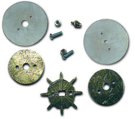
The regions between the teeth can be roughly made as the chain does not touch them. The layers on either side form "shoulders" which support the chain; they must be far enough apart that the "vertical" links can fit between them. The outermost layers guide the chain onto the teeth; they must be far enough apart that the "horizontal" links can fit between them.
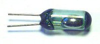
The motor is controlled by a tilt-switch. It's best to attach the switch above the chain wheel. That way, when the motor starts to turn, the mercury is thrown against the contacts and makes a positive contact.
I used a mercury tilt-switch; it's what I had to hand. Nowadays, one should be politically correct and use a non-mercury switch. If you're buying one (a dollar or two), check the current rating (it can be quite low on some modern tilt switches) and the tilt-backlash angle. If it's a low current switch, you could add a transistor.
The attachment of the tilt-switch to the winder should be adjustable so you can set its operating point. I adjusted mine simply by bending the wire leads.
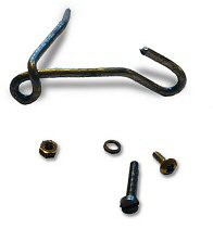
A bracket made from bent coat-hanger wire will hold the weight.
And some odd pieces of plastic will decorate the winder.
Connect wire leads to the motor and switch as shown in the first diagram. Ideally, put a 10nF to 100nF capacitor across the motor and a second capacitor across the switch. That will help prevent sparking: the motor brushes will last longer and there will be less TV interference.
I painted the winder so it would have a pseudo-Victorian distressed "Steampunk" style.
The power wires should be loose and flexible so as not to interfere with the operation of the winder. Electrical power comes from a low-voltage mains PSU (known as a "wall-wart" in the USA; a "swinging brick" in the UK). As a failsafe, you may want to make the wires physically weak so they will break if the switch fails with the motor running and the chain tangles.
The power-wires should be arranged so their weight does not affect the CoG.
You could try making the winder self-contained and running it off two AA cells. It would be neater but I suspect that they'd only last a couple of months. (Assume 1000mAH cells, motor current 200mA, motor operates for 1sec every 5min. Result = 62 days.)
I've marked this project as ongoing because I'm not happy with it. I don't like the "Steampunk" decoration and will change it for a plain wooden box. And I had problems with the motor. The overall design works well but the brushes of the motor burned-out in a month. Since then, I've been looking for a better motor but haven't found one.
It must not be possible to back-drive the motor and that's very hard to find. For reliability, I'd really like a brushless motor and that makes it even harder to find.
I'll keep looking.