 Mitsuru Yamada
1. Main feature
Figure 1 shows the external appearance of the PERSEUS-9. The enclosure is a die-cast aluminum case with external dimensions of 262 mm x 182 mm x 55 mm.
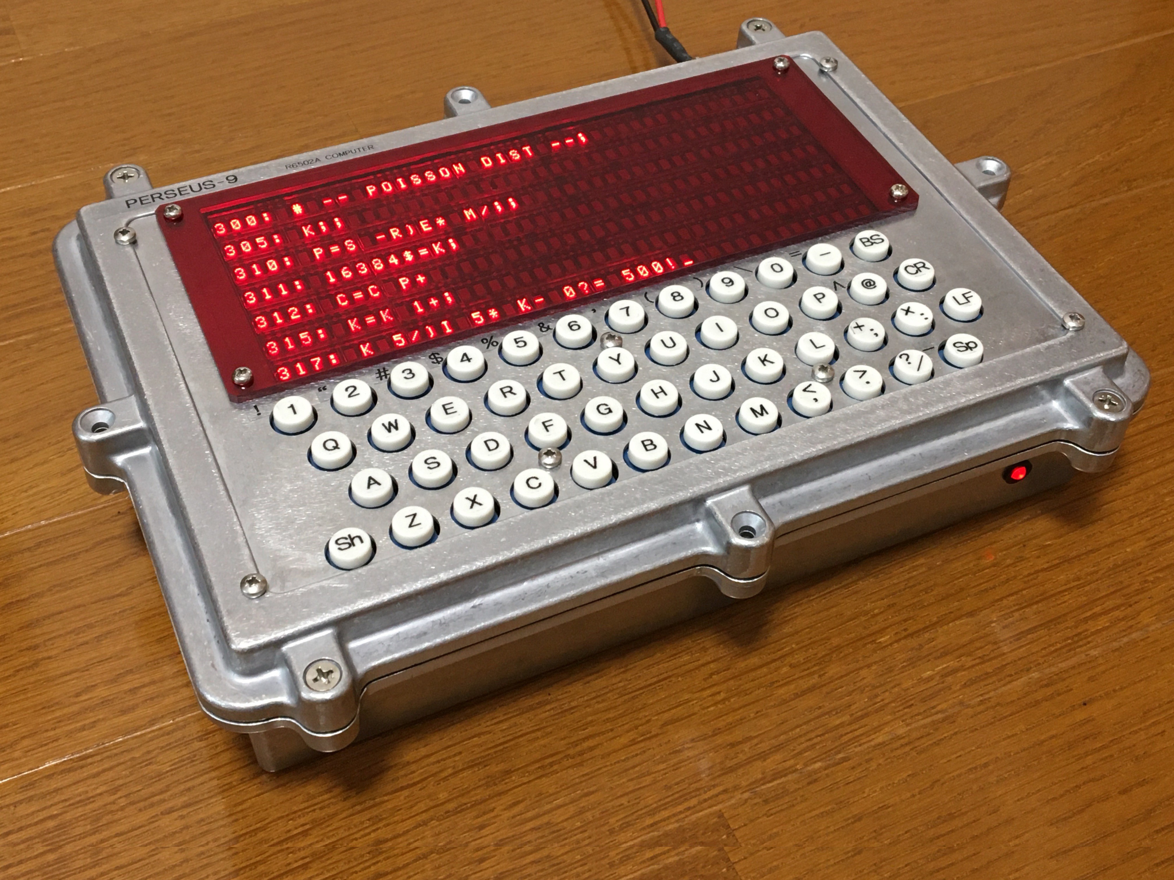
Fig.1 Appearance of PERSEUS-9
The user interface consists of a 48-key keyboard and a 40 x 7 LED character display. The display has been expanded from the 96-character display of the 6802 Serial Terminal to a 280-character display. Power is supplied externally via 5V, 3A power adapter. External Ni-MH 1.2V battery x 4 operation is also possible. User programs are backed up by the built-in battery.
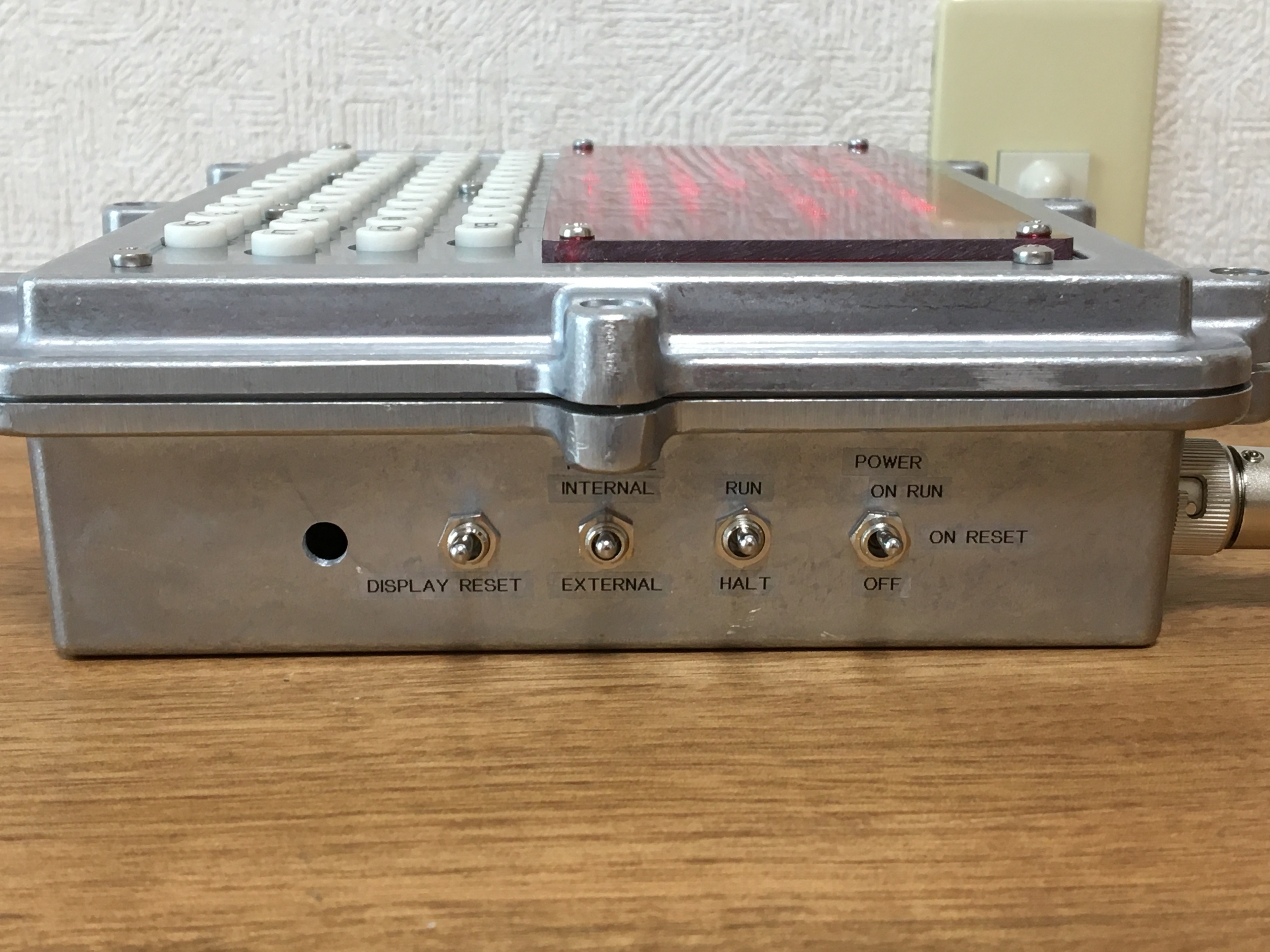
Figure 2 shows the inside of PERSEUS-9. The board has a two-tiered structure, and in this photo PB1, in which the main computer including the 1st CPU and the terminal part including the 2nd CPU are mounted, is visible. PB2, where the key switches and LED modules are mounted, is hidden underneath. The back of the enclosure has a power connecter, three D-sub connectors for the serial interface, and a 26-pin flat cable connector for the parallel interface. On the right side, the power switch, RUN/HALT switch, terminal select switch, and display reset switch are provided.
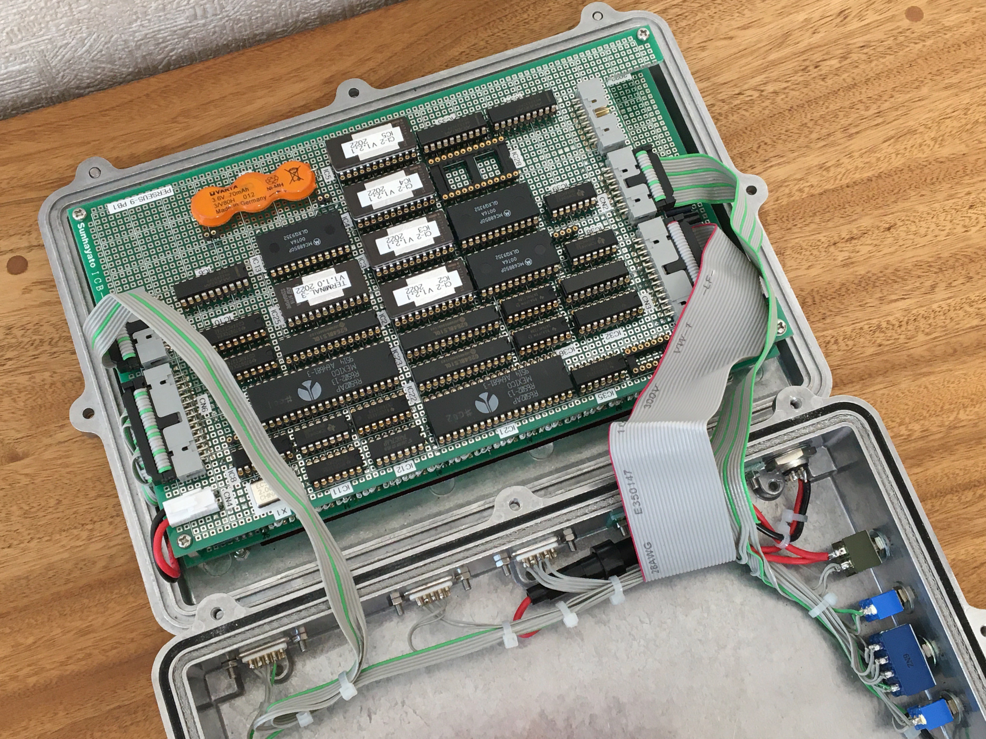
Fig. 2 Inside of PERSEUS-9
2. Enclosure
The enclosure is a die-cast aluminum case HQ-26-18-6N manufactured by Takachi of Japan, which is used. This enclosure is designed to be waterproof and dust-proof for outdoor equipment, but this function is ignored. Although the panel has many openings due to the hole drilling process, it maintains sufficient rigidity. Figure 3 shows the drilling of holes for switches in the panel using a reamer. 3mm-thick red transparent acrylic sheet is used as the filter for the LED display part.
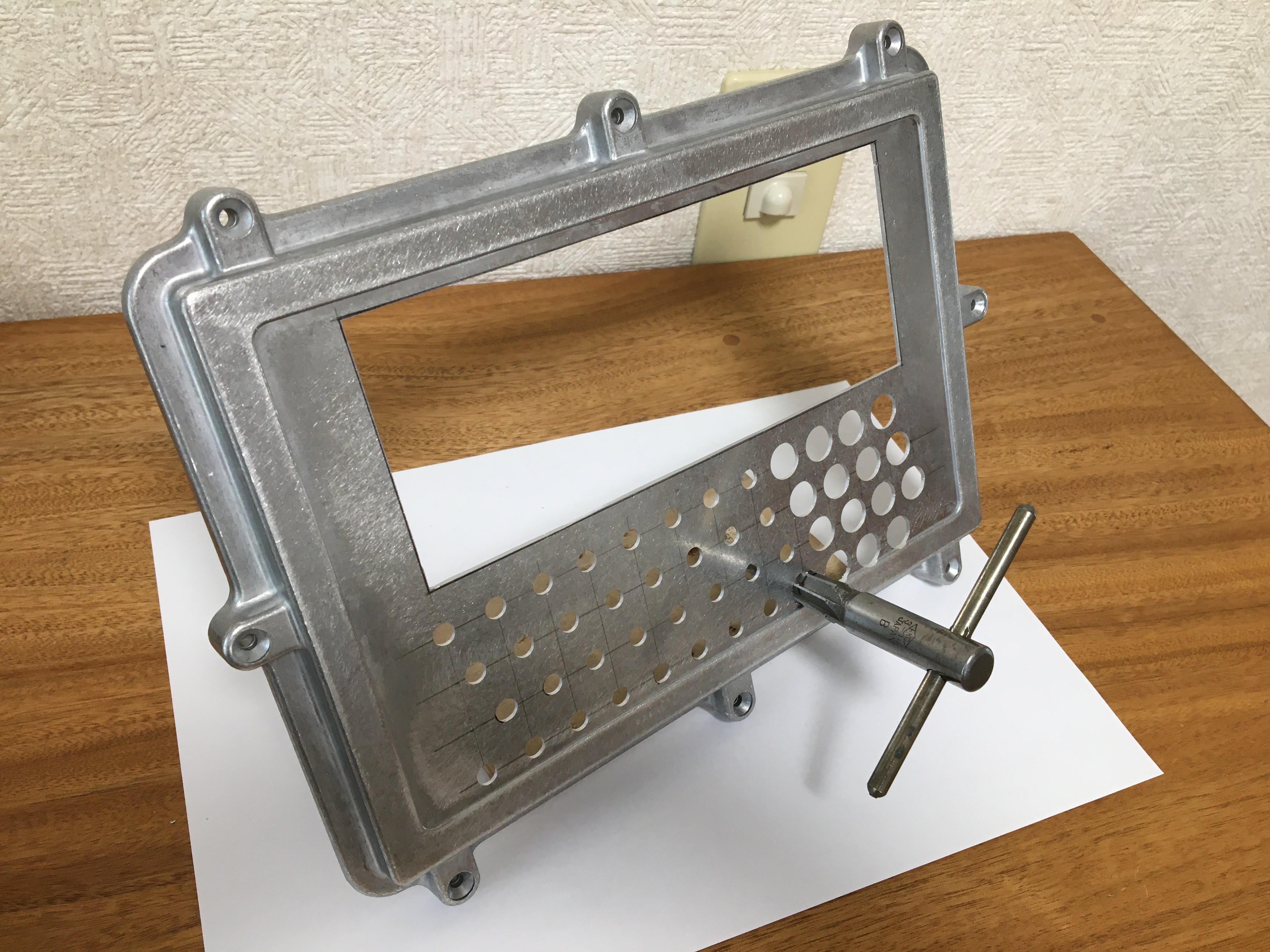
Fig. 3 Reaming work for enclosure
Figure 4 shows the connector holes for the interface and the holes for the toggle switches drilled in the back and sides. Such square holes are drilled continuously with a 3mm-diameter drill, the holes are pulled out, and then finished with a file.
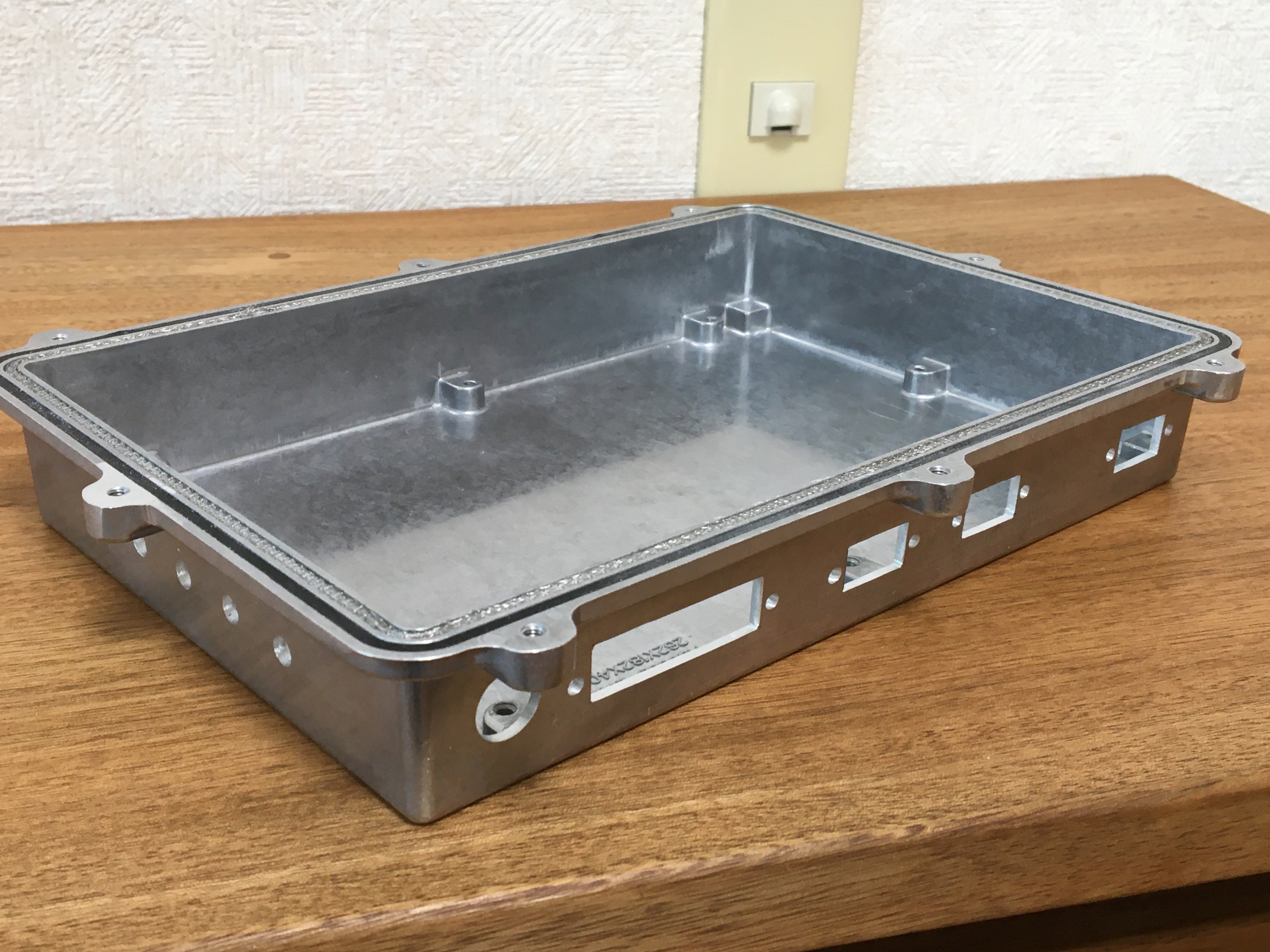
Fig. 4 Enclosure backside
3. Dual CPU hardware configuration
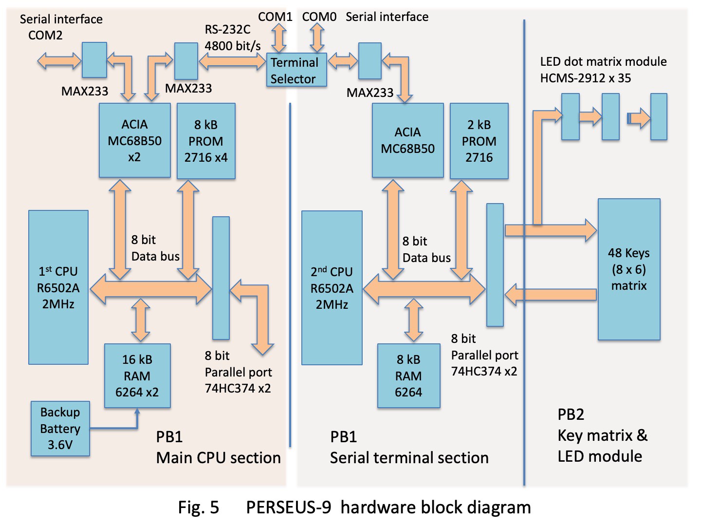
The hardware block diagram of PERSEUS-9 is shown in Fig. 5. The schematic and the parts location figure are shown in the attachment file. In Fig. 5, the left half of PB1 is the main CPU section shown on pages 1 to 3 of the schematic, and the 1st CPU is IC21. This is the almost same as removing the DMA control section which uses toggle switches and LEDs to input addresses and data from the PERSEUS-8 circuit. The main CPU section implements and executes homemade floating point interpreter CI-2 in 8 kB PROM area. The 16 kB RAM space is the user program storage area for the interpreter and the system work area.
The right half of PB1 in Fig. 5 is the serial terminal section including the 2nd CPU shown on page 4 of the schematic. The 2nd CPU runs the serial terminal system software CT-3 on a 2kB PROM. This is basically similar to the 6802 Serial Terminal, but PERSEUS-9 has 2.9 times more LED modules than the 6802 Serial Terminal, so the processing speed needed to be faster. Therefore, the MC6802 (1 MHz) CPU was replaced with a 6502A (2 MHz). This resulted in a 6502 (2 MHz) dual-CPU configuration for the entire PERSEUS-9. This is not a recent CPU configuration with many cores, but it is a configuration with a main CPU and an I/O CPU, which was common around 1980. The two computer parts have the same address mapping to facilitate hardware operation verification. For example, the ROM and flat cable of the terminal part can be replaced with the main part to verify the operation as a terminal.
4. Peripheral devices
In Fig. 5, PB2 consists of 48 key switch matrices and 35 5x7 dot 8-character LED modules (HCMS-2912) shown on page 6 and page 5 of the schematic. The data lines of the LED modules are connected in cascade. And all of these are connected to the 8-bit parallel port of PB1 serial terminal section shown on page 4 of the schematic.
The main CPU section has a 2-channel serial interface and a 1-channel 8-bit parallel I/O interface as shown on page 3 of the schematic. The serial interface consists of two ACIA (Asynchronous Communication Interface Adapter) MC68B50 and MAX233 for RS-232C level conversion. The parallel interface consists of an Octal D-FFs standard logic IC, 74HC374. Figure 5.1 shows an example of the use of this parallel interface with a homemade PROM programmer connected.
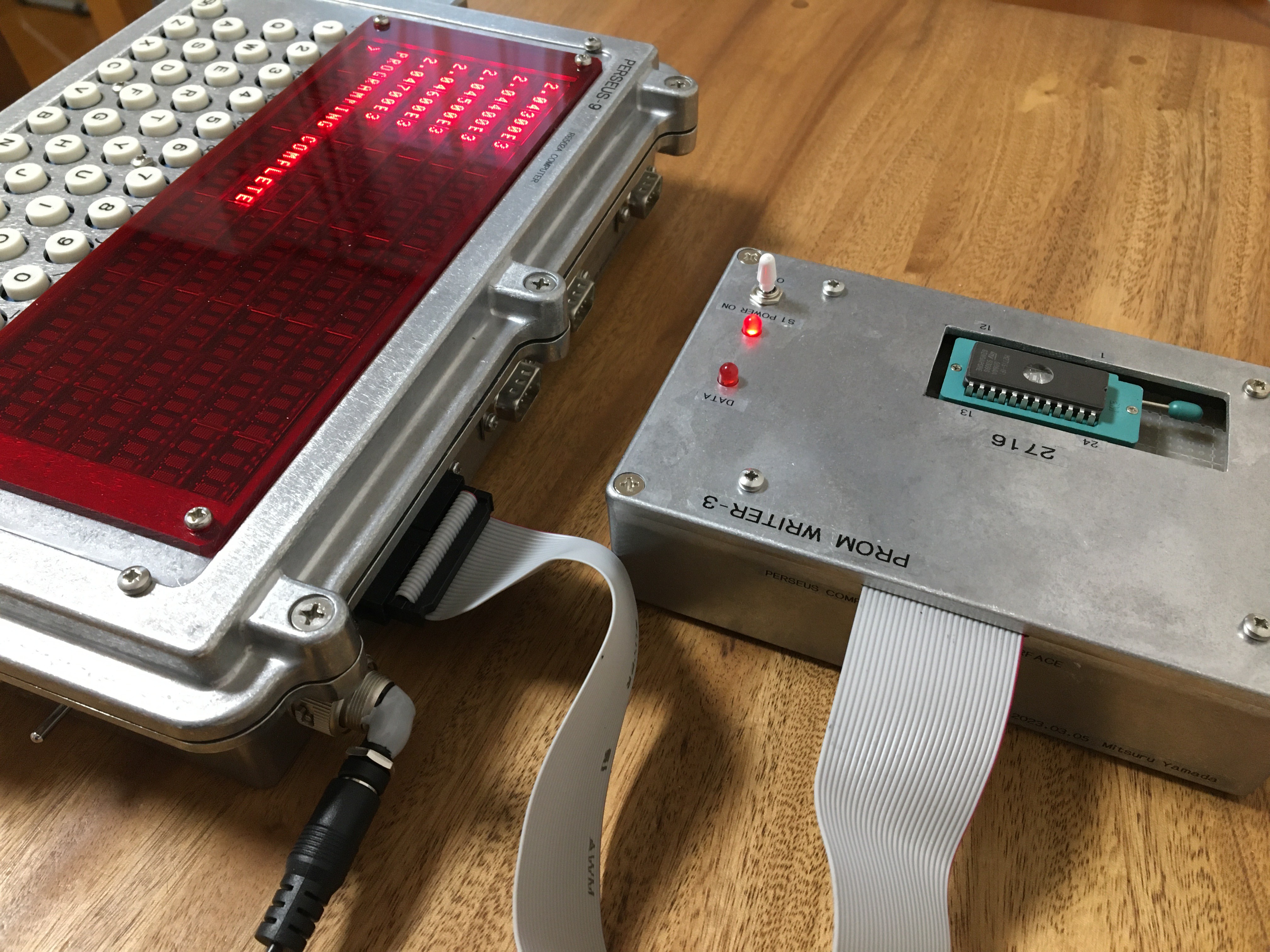
Fig. 5.1 Homemade PROM programmer connected to the parallel interface
Figure 5.2 shows another connection example of this parallel interface, a home-made PROM module EXTROM-2 for application program loading.
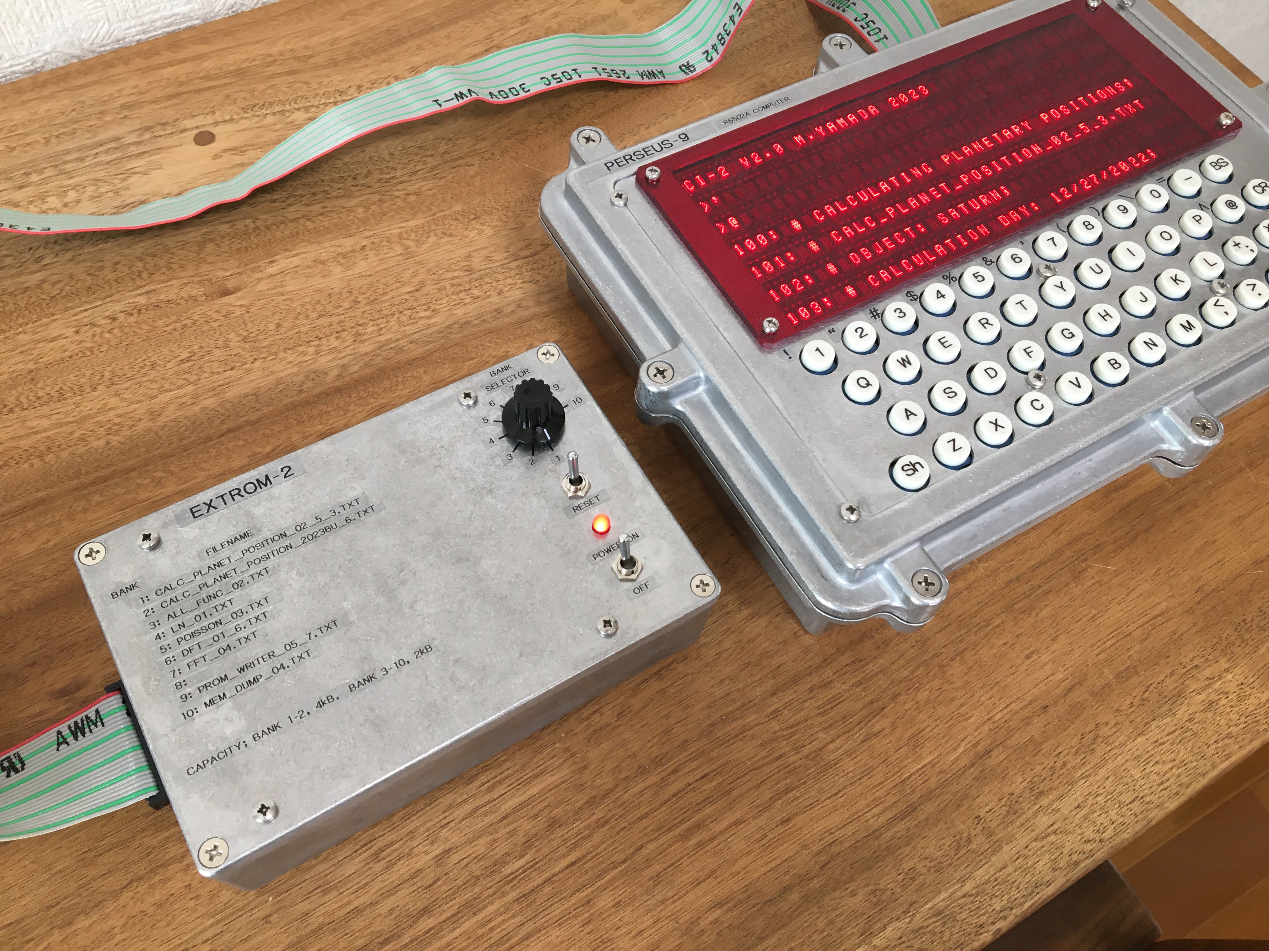
Fig. 5.2 Homemade PROM module EXTROM-2 connected to the parallel interface
The terminal selector in Fig.5 switches the serial data lines with toggle switch S3, as shown in the schematic page 7. When the connection is internal, the PERSEUS-9 alone can operate the interpreter via keys and LED displays on the panel. When the connection is made external, the serial lines connecting the main computer and terminal are disconnected and connected to the COM1 and COM0 connectors, respectively. An external PC or other device can be connected to COM1 to operate the interpreter or load and save user programs. Also, by connecting an external device to COM0, the PERSEUS-9 can be operated as a simple serial terminal.
5. Component placement
The PB1 component face of PERSEUS-9 is shown in Fig. 6. The left half is the main computer part, with the 1st CPU IC21 at the top. The two ICs IC22 and IC23 below it are the HM6264 with 8kB RAM, and below that are four 2kB ROMs 2716 IC2, IC3, IC4, IC5 with home-made floating-point interpreter CI-2 system software written in them.
The two 24-pin ICs in the left center are MC68B50 for serial interface. To the right of the flat cable connector is a parallel port configured with a CMOS standard logic IC32, IC31 SN74HC374.
The right half of Fig. 6 is the serial terminal section, with a crystal X1 for clock oscillation and a CMOS standard logic IC at the top. Below that is the 2nd CPU IC1. And below that is the HM6264 RAM, the 2716 ROM for the serial terminal system software, and the MC68B50 for the serial interface. The orange component at the bottom of the board is a rechargeable nickel-metal hydride battery to back up the entire 16kB RAM area of the main computer section.
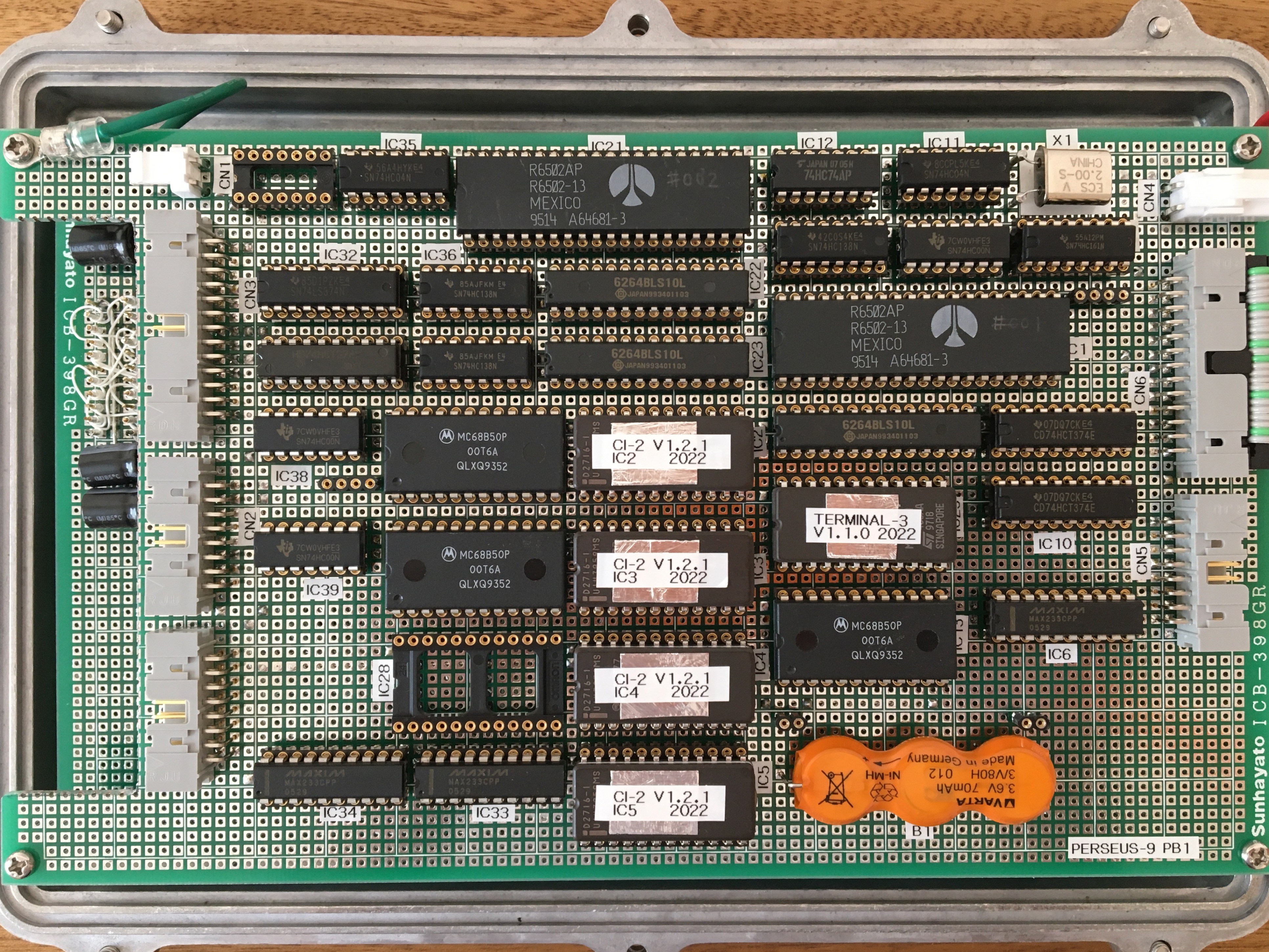
Fig. 6 PERSEUS-9 PB1
The PB2 component face of PERSEUS-9 is shown in Fig. 7; the top half of PB2 is the 35 5x7 dot 8 characters LED module IC40-IC74 HCMS-2912. This LED dot module does not have a built-in font, so the bit pattern of the font to be displayed must be serially input. The character size is 3.71mm in height, smaller than the 4.57mm type used in the 6802 Serial Terminal. The lower half of PB2 is the keyboard portion, which consists of an 8x6 matrix with 48 DS660RCW pushbutton switches S4-S51 and switching diodes D4-D51. The keys are spaced 15.2 mm apart. The letters on the key are printed on transparent tape by using a label maker and attached to the key top.
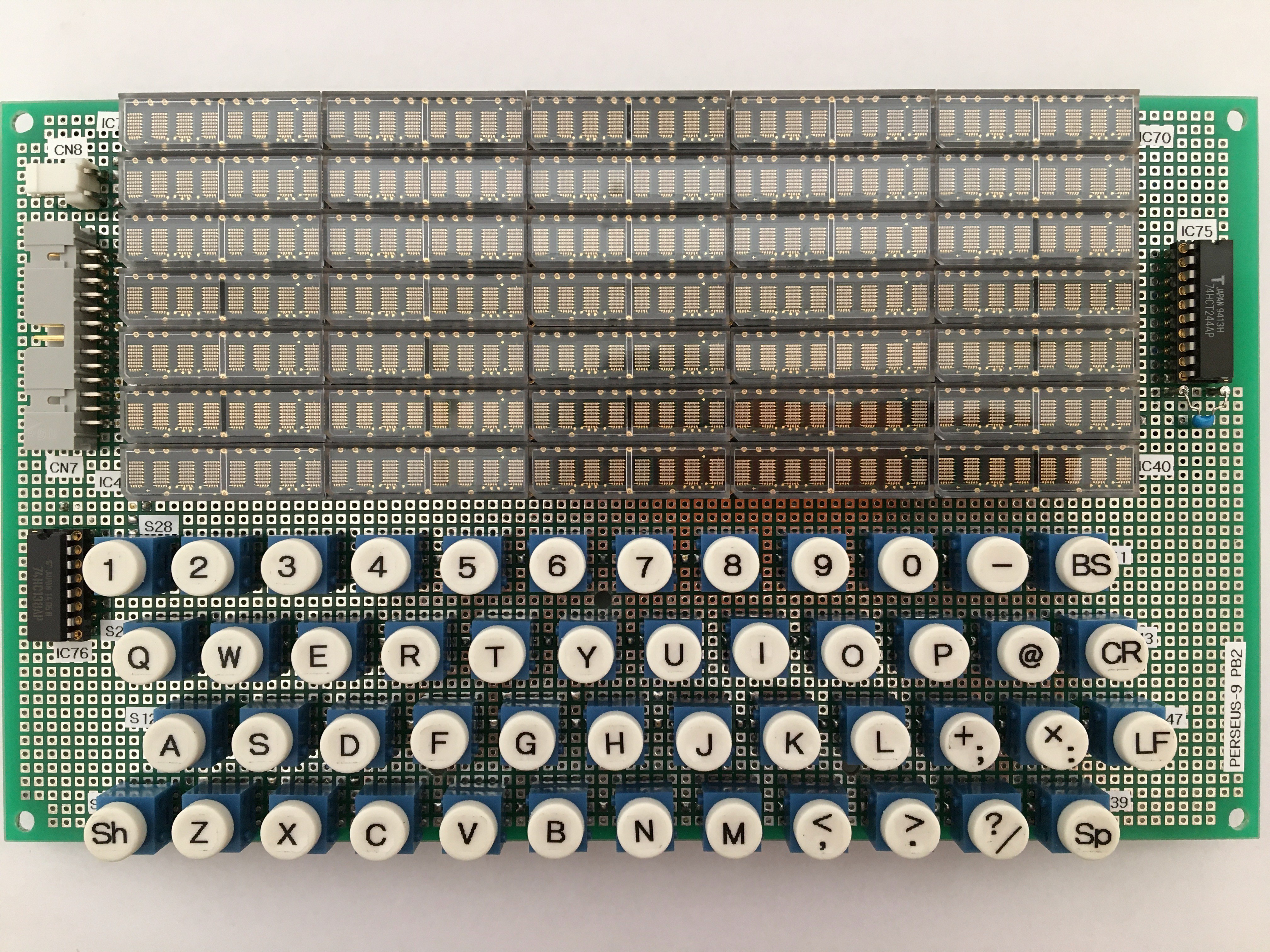
Fig. 7 PERSEUS-9 PB2
6. Build
The printed circuit board is a universal board, and the circuit wiring was done by wire wrapping. This is the same technique introduced in PERSEUS-8. The ground and +5V lines of the power supply were wired by soldering tinned wires; the wiring surfaces of PB1 and PB2 are shown in Fig. 8 and Fig. 9, respectively. Because the boards are stacked in two layers, the height of the wire wrap pins is trimmed down to approximately 7 mm.
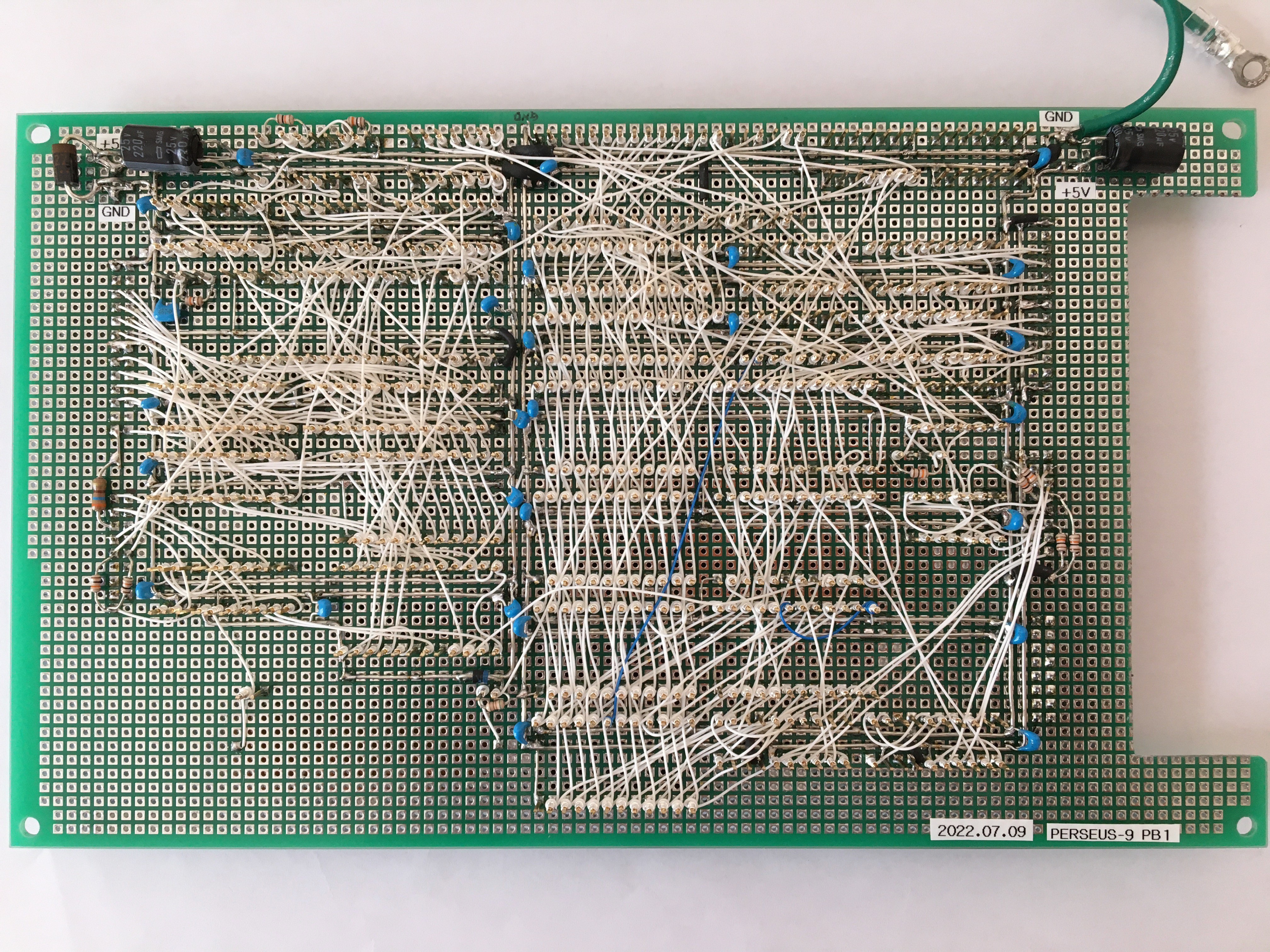
Fig. 8 PERSEUS-9 PB1 wiring side
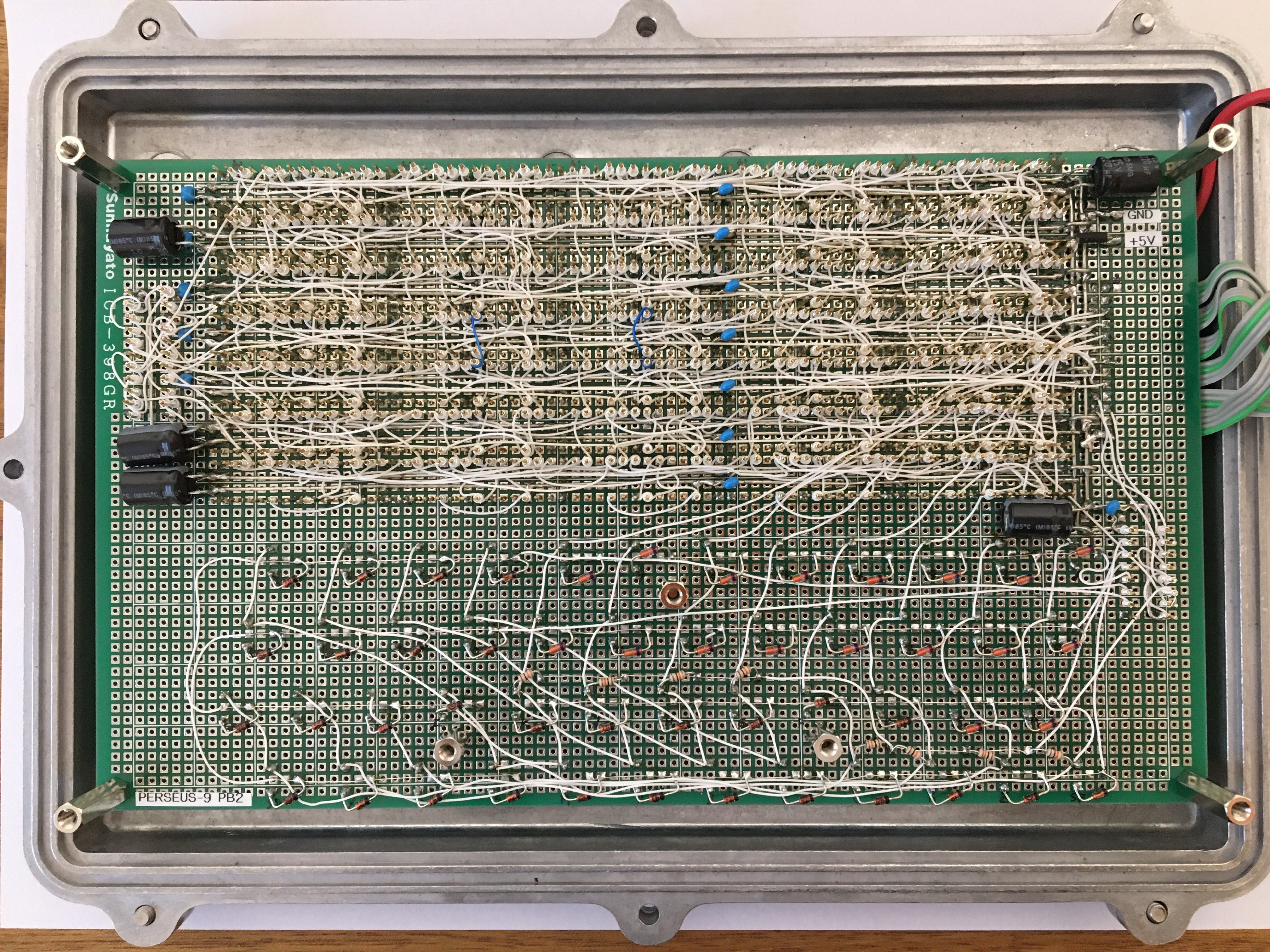
Fig. 9 PERSEUS-9 PB2 wiring side
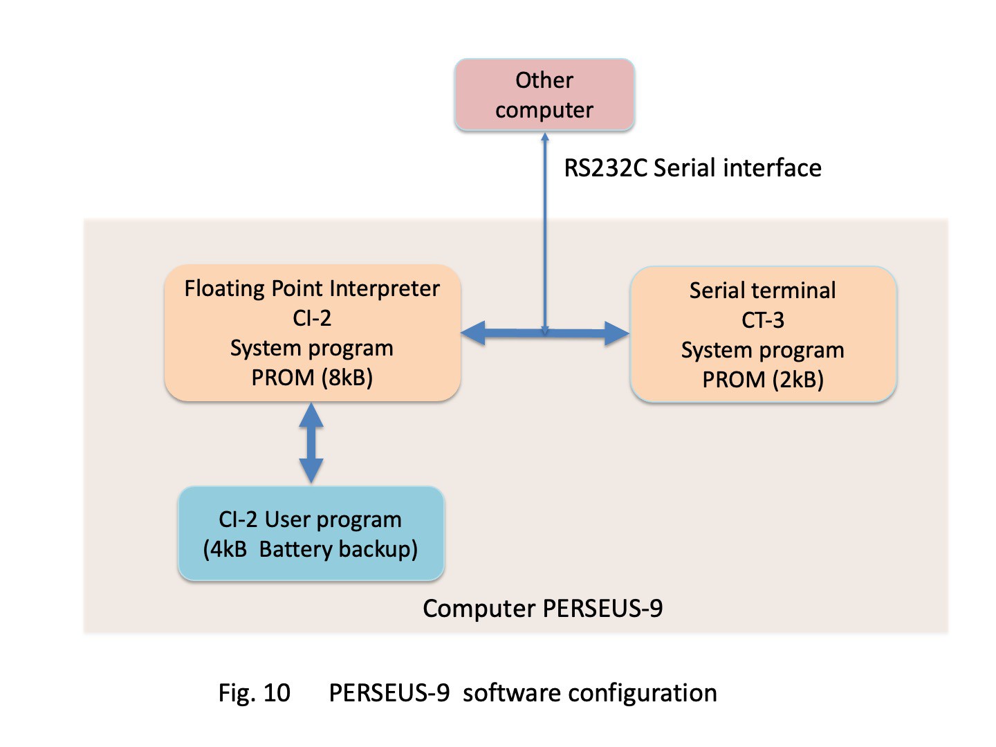
7. System software configuration
The system software of PERSEUS-9 consists of the floating-point interpreter CI-2 and the serial terminal section CT-3 as shown in Fig. 10. CI-2 is executed by the 1st CPU and CT-3 by the 2nd CPU in Fig. 5. The floating point interpreter CI-2 is implemented directly by using the PROMs developed for PERSEUS-8. The details of this interpreter are described in another project, Homemade Floating Point Interpreter for 6502. The linked video shows updating these PROMs. There is no audio explanation, so please turn on the subtitles to watch.
The user program code executed by this interpreter is stored in the RAM of the main CPU section shown in Fig. 5. This user program can be input and debugged from the serial terminal section. It can be saved to an external PC via the RS-232C serial interface COM1 and it can also be loaded from an external PC.
8. Terminal section system software
The configuration of the CT-3 system software for the terminal section is shown in Fig. 11. The CT-3 assembly code is shown in the attached file and the implementation addresses of some processes are listed in Fig. 11. Like the 6802 serial terminal, the PERSEUS-9 performs key matrix scanning, ASCII code conversion of key press detection codes, and serial interface transmission in a single task. At the same time, when a character is received from the serial interface, it also performs buffer scrolling and backspace processing.
In Fig. 11, "Update display for entire buffer" updates the display for the entire buffer. This process repeats to acquires one character from the buffer with "Get one character from buffer" and then updates the display with "Send fonts to LED modules for one character". This update process refers to the font table from the character code to obtain a 5-byte bit pattern. This 5-byte data is then serialized and sent to the LED modules. The data is written to the LED module at the point on the rising edge of CLK after the data is set. These write control signals CLK, RS, and CE lines shown on page 5 of the schematic are also controlled by software. After this moment, the receive flag of the serial interface is checked, and if it has been received, the "Scroll buffer" process is performed. This includes processing of backspace codes. Above it takes 0.78 ms to update the LED for one character.
"Scan keys" scans all 48 switches. A binary value is output from the port, which is decoded and a pattern is applied to the key matrix with only one of the eight lines at a low level. If a key is pressed, the bit pattern of the read port corresponding to the key will be changed, and the ASCII code is obtained from that bit pattern by referring to a table. If a shift key press is detected, the next key press is detected as it is and converted to the code corresponding to the shift in a different table. The obtained ASCII code is sent out as a single character from the serial interface. The key scan takes 0.21ms to confirm all key presses. Since key switch bouncing lasts up to 10 ms, key scans are performed every 25 ms with 32 characters display updates cycle to detect stable switch position.
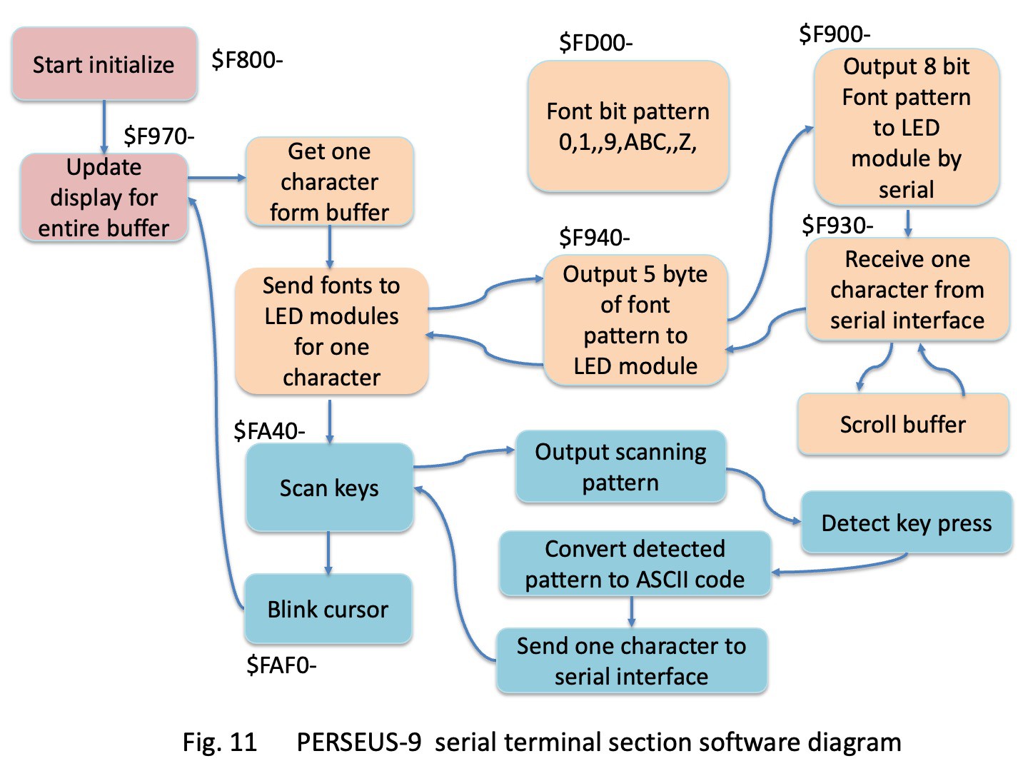
Above all process is performed for 280 characters for the entire buffer, the execution time is 0.78ms x 280 + 0.21ms x (280/32) = 220 ms. This is the rate of display update. Cursor blinking is also processed here.
This system software CT-3 for the terminal section was newly hand-assembled and coded for the 6502. Debugging of the code was done by connecting the parallel port of PERSEUS-8 to PB2 of PERSEUS-9 and using PERSEUS-8 as an emulator of the terminal section of PERSEUS-9, as shown in Fig. 12. The binary codes were input to the RAM of PERSEUS-8 with toggle switches operation, and debugging was completed with single-step execution. The debugged machine codes were written to a PROM with a homemade PROM programmer.
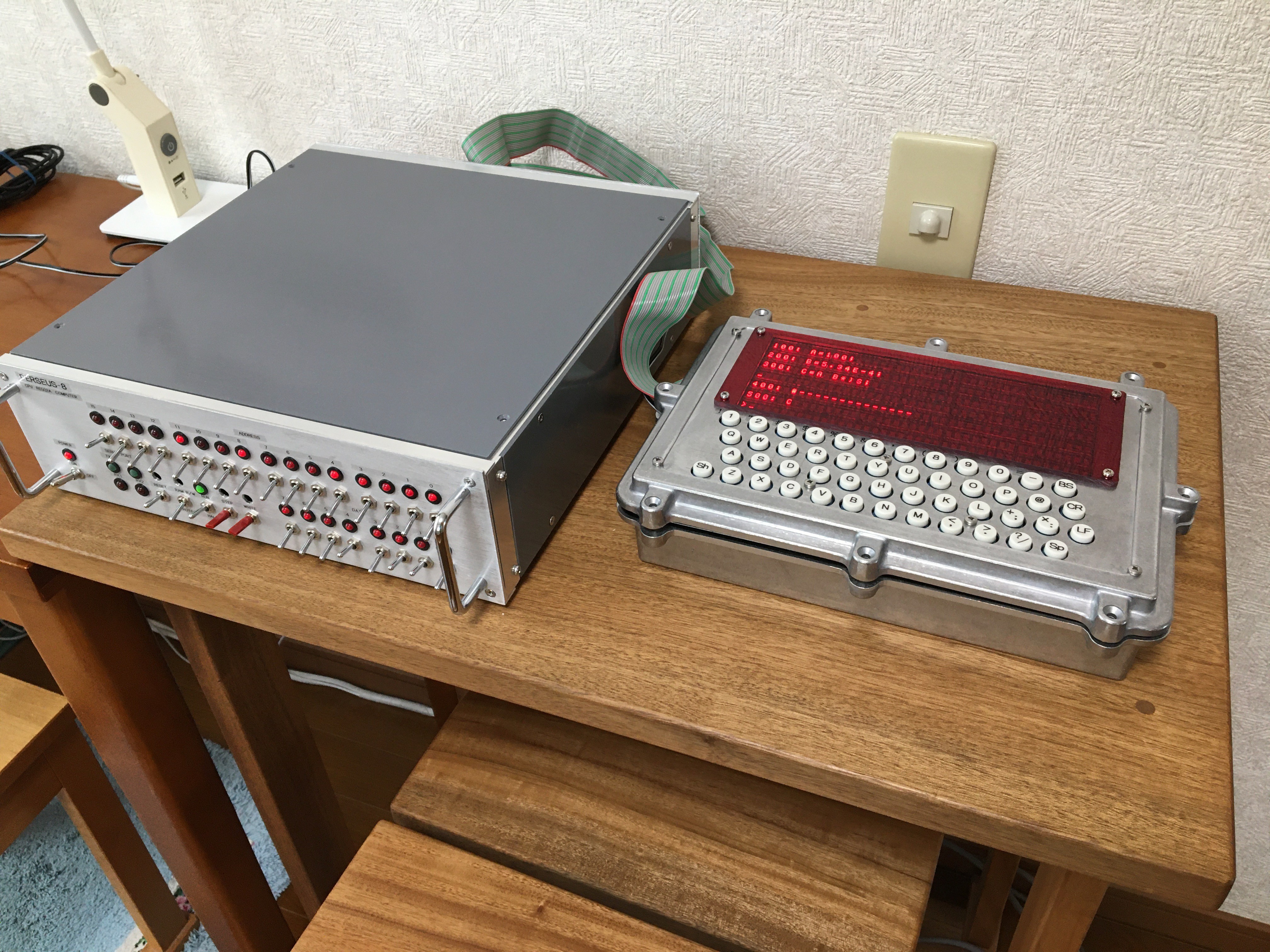
Fig. 12 Emulation for terminal section by using PERSEUS-8
9. Program loading
Currently the user program is saved even when the power is turned off by the RAM backup of the built-in battery, which is quite convenient for a single program. However, at present, there is no software equivalent to a filing system. Therefore, to efficiently replace and run multiple user software programs, I use a program list saved as a text file on an external PC and loaded in terminal external mode. Video 1 in the following shows how the user program is loaded from an external PC. The user program CALC_PLANET_POSITION_02_5_3.TXT that is loaded and executed calculates the desired date and time position of the planet from the orbital elements.
Video 1 Loading a program from an external PC terminal, and execution of its program to calculate the position of the planet.
Then, to enhance for user program loading, I made my own PROM module EXTROM-2 that connects to the parallel interface. The application is selected by a rotary switch on the module shown in Fig. 5.2. This allows the current 10 major applications to be loaded immediately by the new loading command ' ' ' of CI-2. The addition of this command was implemented in CI-2 version 2.0.0.
10. Results
I have succeeded in building my own 6502 dual-processor mobile computer, PERSEUS-9, which is about 5 cm thick, but has about the same dimensions in length and width as a current notebook PC. The PERSEUS-9 is technically a synthesis of the development emulation system of the PERSEUS-8 and the results of hardware and software development with the home-made floating-point interpreter CI-2 and the 6802 Serial Terminal. The CI-2 floating-point interpreter performed as well as the PERSEUS-8. Floating point four arithmetic with RPN, calculation of elementary functions, input and modification of user programs with the line number editor, and execution of application programs such as Fast Fourier Transform (FFT) can be performed in the same way as with PERSEUS-8. Attached is an example application program, MEM_DUMP_04.TXT, which uses pointer variable for memory access and dumps memory data as shown in line 130, 131 and 246 in the program list.
The following Video 2 is an introductory video of the PERSEUS-9. This video shows the process of assembling the board into the enclosure, turning on the power, starting the interpreter, and displaying and executing a list of user programs. There is no sound, so please turn on subtitles. This example user program POISSON_03.TXT calculates the probability and cumulative distribution of the Poisson distribution of mathematics. The calculation is programmed using the exponential function implemented in CI-2, which is described as ")E" in line 310 of the program file POISSON_03.TXT. The calculation results of the probability and cumulative distribution are shown at the end of the program file, which confirms the computational practicality of the floating-point type.
Video 2 Assembling the PERSEUS-9, power on, startup the interpreter and execute an example user program
Video 3 in the following shows another example user program ADC_02.TXT that accesses a homemade SAR AD converter connected to the parallel interface of the PERSEUS-9 and displays the DC voltage. The parallel port is accessed by a pointer variable provided in the CI-2.
Video 3 AD conversion and voltage display example
Video 4 in the following shows an example of creating a very simple program with the interpreter's line number editor on this computer. This program consists of three lines, setting the initial value of variable A to zero and adding 1 until it reaches 5. After its execution, a new line will be inserted that calculates the natural logarithm of the variable.
Video 4 Simple programming example on PERSEUS-9
Following video 5 shows an example of a PERSEUS-9 application used to display the coordinates of an astronomical telescope mount. The pulses of the stepper motor that drives the mount are counted by dedicated hardware, and the CI-2 user program reads them via the parallel interface, converts them into coordinate values, and displays them. The details of this are explained in another project 'Telescope Mount Controller using PERSEUS-9'.
Video 5 Telescope mount controller using PERSEUS-9
The power consumption of PERSEUS-9 is 2.6W (5V, 0.52A) when the screen display shows only one underscore character, and 9.5W (5V, 1.9A) when the @ character is displayed on the full screen. 4.8V of 4 NiMH AA batteries can be used instead of the 5V power adapter to operate for about one hour. However, since there is no function to prevent the CPU from running out of control due to a drop in power supply voltage, care must be taken when the voltage drops.
As described above, I was able to create a computer for myself that can be easily used for calculations in place of a calculator and for simple mathematical and physical programming calculations. Furthermore, I can easily experiment with direct access to the parallel interface by using pointer variables. Comparing the floating-point arithmetic error of my interpreter with the results obtained by the current PC-based computation language system is endless interest to me.
References
[1] R6500 MICROCOMPUTER SYSTEM HARDWARE MANUAL, Rockwell international.
[2] HCMS-29xx Series High Performance CMOS 5x7 Alphanumeric Displays Data Sheet, AVAGO TECHNOLOGIES.
[3] M2716 16k (2k x 8)UV ERASABLE PROM data sheet, intel.
[4] HM6264 Series 64k SRAM (8-kword x 8-bit) data sheet, HITACHI, 1997.
[5] MC6850 ASYNCHRONOUS COMMUNICATIONS INTERFACE ADAPTER data sheet, MOTOROLA SEMICONDUCTORS.
(Posted on Jul. 23, 2022)
(Latest revision on Feb. 03, 2024)