 Lithium ION
There are two types of piezoelectric buzzers available in market which are categorized as passive buzzers and active buzzers. In this article, we will see the main difference between two and how to use them in your project. Buzzers are not used only for notifications but also, they can produce different tones. We will pair these buzzers with Arduino and write a minimal program for them. Build your own Arduino microcontroller using PCBWAY prototype service. Sign-up now and get new user coupons to order first PCB prototype.
Active and Passive buzzers:
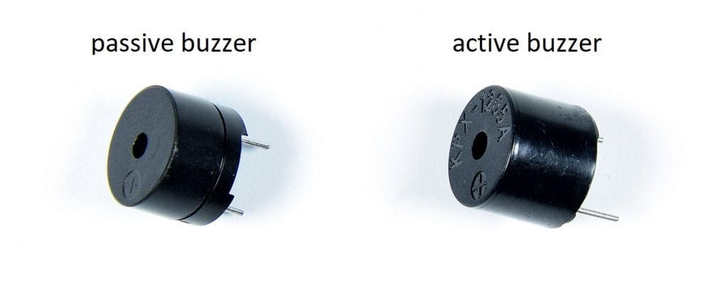
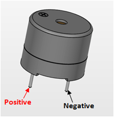
Active buzzers are called active because they can produce sound directly when connected with the battery. Active buzzers can produce a single tone which is tuned to 2khz by most of the manufacturers. On the other hand, Passive buzzers need a triggered wave to produce sound. So, these passive buzzers can produce a number of different tones based on the input frequency of signal. All type of buzzers is polarized, positive and negative terminal is mentioned on them. Connect positive to the positive of battery and negative to negative.
These buzzers can’t be distinguishable only be looking. Connect them to battery keeping polarity in mind, active buzzer produces a loud tone and passive buzzer just produce a pop sound.
Basic working Idea of buzzer:
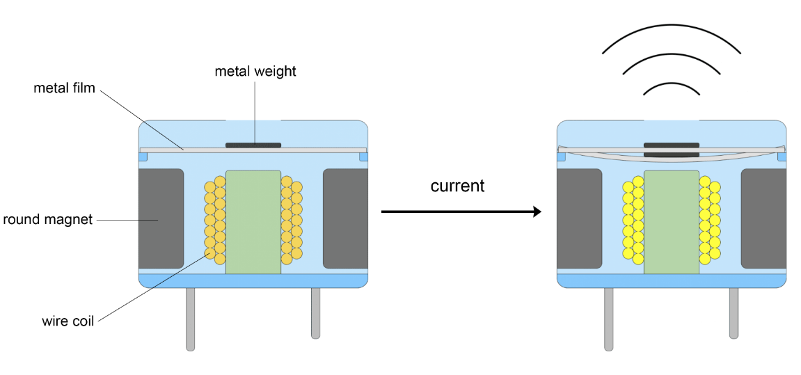
The basic idea of producing sound is by vibrations. As in human vocal cords the sound outcome is defined by the vibrations. Similar idea is there in Buzzer a coil is attached to the connecting points positive and negative.
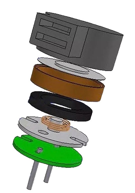
And placed between the two magnets which vibrate the system when buzzer is powered. The coil is further attached to a thin metal plate with a small weight in middle which produce the sound.
Connecting the active buzzer with Arduino:
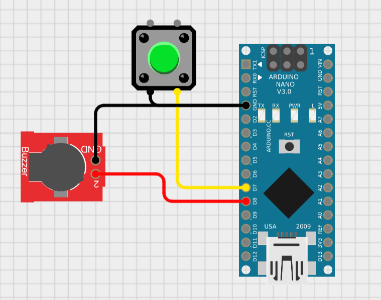
First, these buzzers can be directly connected to any digital pin of Arduino and then We make a loop to turn on/off the buzzer on any event based on time, voltage and state of switch. The example given below shows how we can control the buzzer using a tactile button state.
int buzzerPin = 8;
int buttonPin = 7;
void setup() {
pinMode(buzzerPin, OUTPUT);
pinMode(buttonPin, INPUT_PULLUP);
}
void loop() {
int buttonState = digitalRead(buttonPin);
if (buttonState == LOW) {
digitalWrite(buzzerPin, HIGH);
}
if (buttonState == HIGH) {
digitalWrite(buzzerPin, LOW);
}
}
The button state is pulled up using the input pullup function and in the loop section you can see the buzzer is high only when the button state is low and vice versa. Whole the circuit can be powered using a 5v power supply.
Connecting passive buzzer to Arduino:
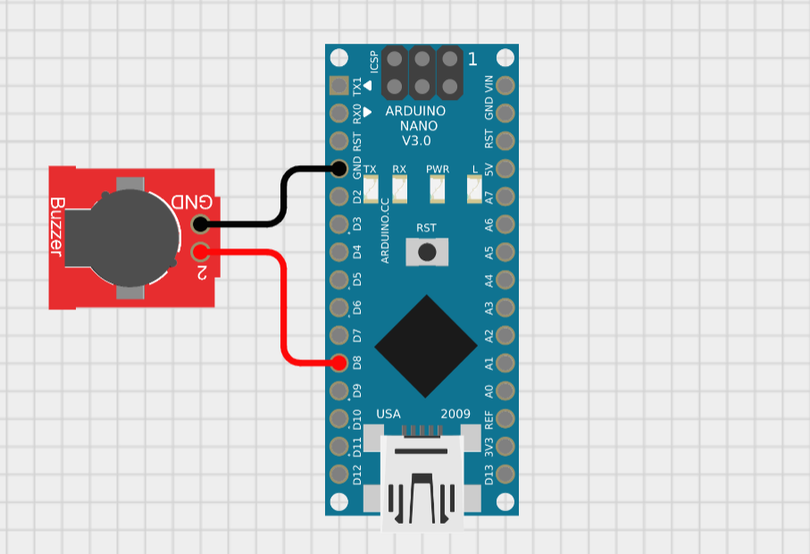
The passive buzzer tone can be controlled using the frequency applied to it, Arduino can produce a square wave through digital pins. And by adjusting the time for high or low of square wave, we can change the frequency and hence the tone.
Arduino has a tone() function, which helps to generate the desirable frequency wave on digital pins.
tone(pin, frequency, duration); // tone function take 3 parameters to define output, first id the digital pin number, the frequency of output wave and the duration for which you want to send the output.In the similar way to keep buzzer silent over time we can use no tone() option. Here is a small code to try with this function.
int buzzerPin = 8;
void setup() {
pinMode(buzzerPin, OUTPUT);
tone(buzzerPin, 1000, 2000);
}
void loop() {
tone(buzzerPin, 440); // A4
delay(1000);
tone(buzzerPin, 494); // B4
delay(1000);
tone(buzzerPin, 523); // C4
delay(1000);
tone(buzzerPin, 587); // D4
delay(1000);
tone(buzzerPin, 659); // E4
delay(1000);
tone(buzzerPin, 698); // F4
delay(1000);
tone(buzzerPin, 784); // G4
delay(1000);
noTone(buzzerPin);
delay(1000);
}
The digital pin is declared as buzzerPin and set equal to 8, the setup is designed so that on first power on it will produce a 1000hz sound for 2 seconds. Then the loop section is executed which contains notes of different frequencies, the duration parameter is not used here due to execution problems. But for the same a small delay can be placed after each tone which helps to distinguish the sound effect.
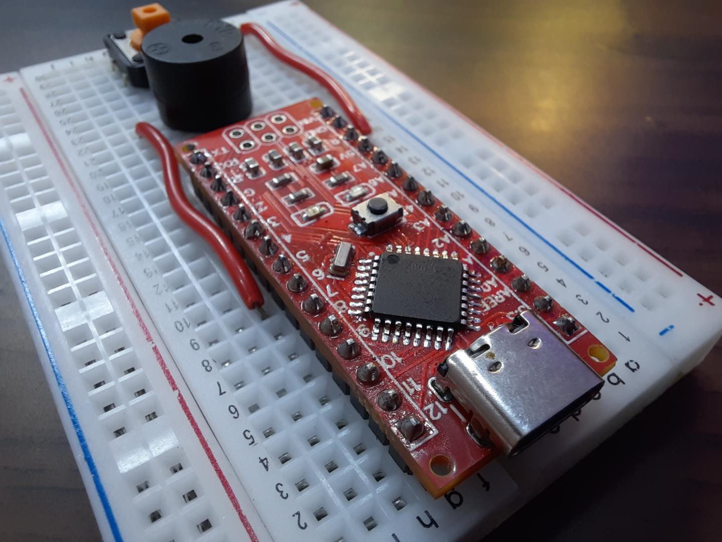
Want to make your own Arduino development board:
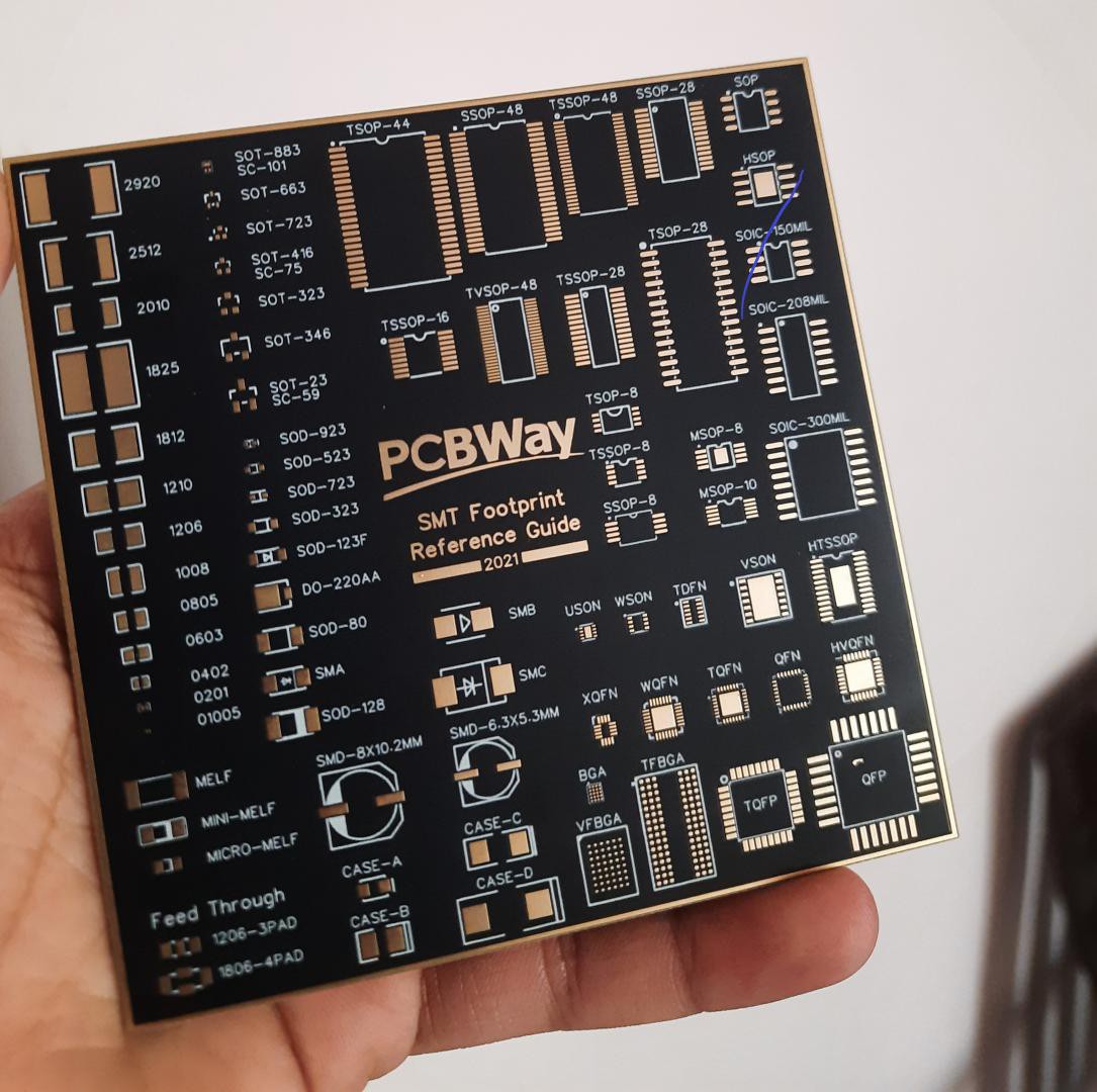
I made my own Arduino Nano microcontroller board using PCBWAY prototype service. I designed this PCB and then ordered it from PCBWAY. The ordering process is quite easy just fill the parameters of board choose color, thickness and type of finishing and then add it into cart.
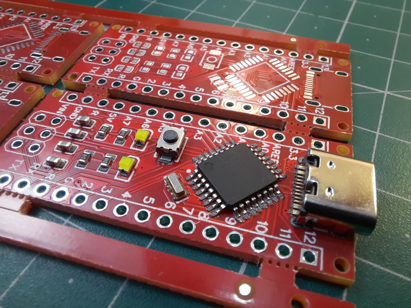
Upload your Gerber files and you will get the quote within 1 hour, You can discuss the specifications with the PCBWAY engineering team. For these PCB layouts I choose red color, Hasl finishing and I got 5pcs these amazing quality boards just in $5. Visit PCBWAY from here and see full article on Arduino making from here.