 Marek Więcek
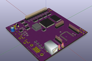
At the beginning I wasn't even sure if the chips I got are in working condition. Without any compatible device I wasn't able to simply test them. Because of that I ditched my initial idea to design and etch PCB for this project. Instead I decided to build the device on universal board, using wire. This way I was able to build one functional block, test it ant then move to another. First step was to wire just a CPU and test it by forcing NOP instruction execution with resistors. Then I wired memory and executed simple code for blinking LED connected to CPU integrated IO. When that worked just fine, I finally added graphic chip, cartridge slot and pad connectors, using low-res scans of schematics I found on-line as my only reference.
After triple checking all connections I finally began testing it with cartridges from my collection. It didn't work right away. Initially there was this weird issue - sound was perfectly fine and CPU was obviously doing something, but image on the screen was scrambled. I was really close to ditching entire project, fortunately I found the cause that turned out to be trivial - video memory chip was a little bit too slow.
At this point there was only one lat thing to do - putting board inside case. Initially I considered 3D printed enclosure, but ultimately I decided to use metal case, which required some manual work with drilling and cutting holes for connectors and cartridge slot, but it was worth it. I am really pleased with the final result.
 london almida
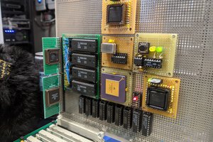
 Jason Westervelt
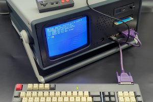
 nullvalue
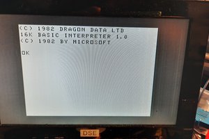
 Matt Callow