 John Anderson
Now that the case and the PCB are prepped and you have soldered the headers that will connect the controller board to the original PCB, you can start building the controller board.
Start by putting a solder blob on both sides of the proto board connecting the left and right side power bus.
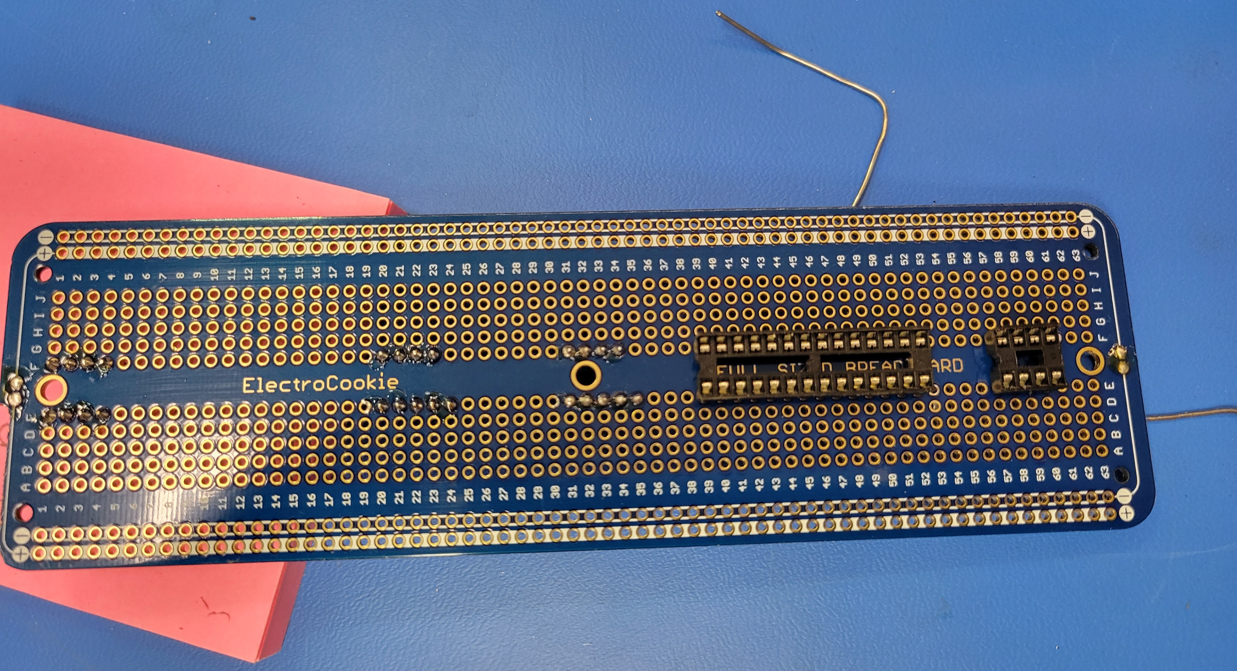
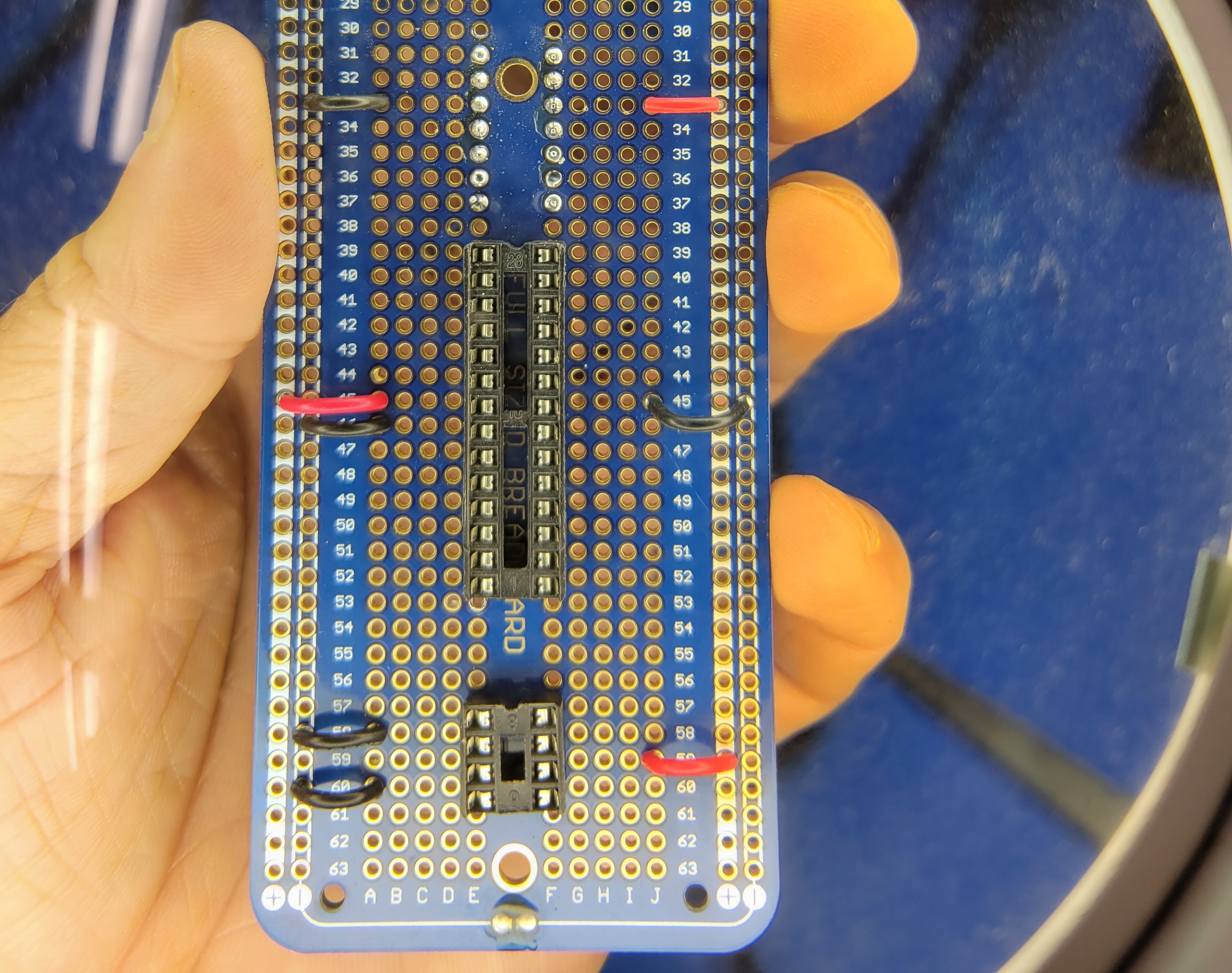
Then locate the 28 pin dip and 8 pin dip sockets on the protoboard as so. If you align them on the same rows I have it will make referencing this photos easier. On my board, pin 1 for the 28 pin dip socket is on row 39 and pin 1 for the 8 pin dip socket is on row 57.
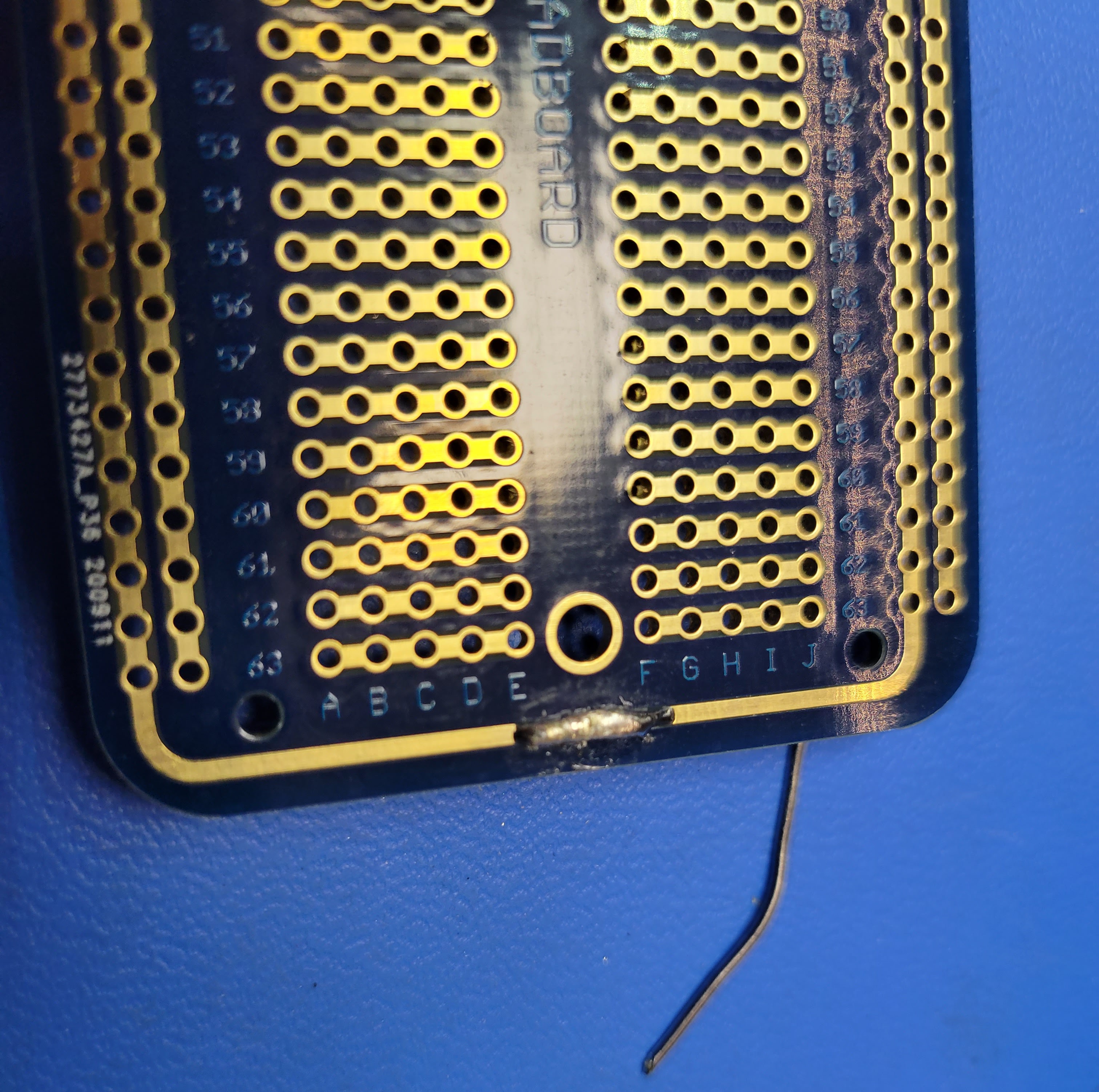
Next wire up the power and ground to the power bus. Wiring power and ground to the headers will provide 5v and ground to the controller board. Wiring power and ground to the 28 pin and 8 pin sockets will provide 5v and ground to the microcontroller and op amp. Note: I have soldered some of the rows adjacent to the headers so that you can see all the pins for IC5, IC6, and IC7. This will help reference the pin numbers for these. Pin 1 for these three is the upper left. Therefore pin 1 for IC5 is the upper row 7, pin 1 for IC6 is the upper row 26, and pin 1 for IC7 is the upper row 37. Pin 1 for the 28 pin microcontroller is the lower row 39 and pin 1 for the 8 pin audio op amp is the lower row 57.
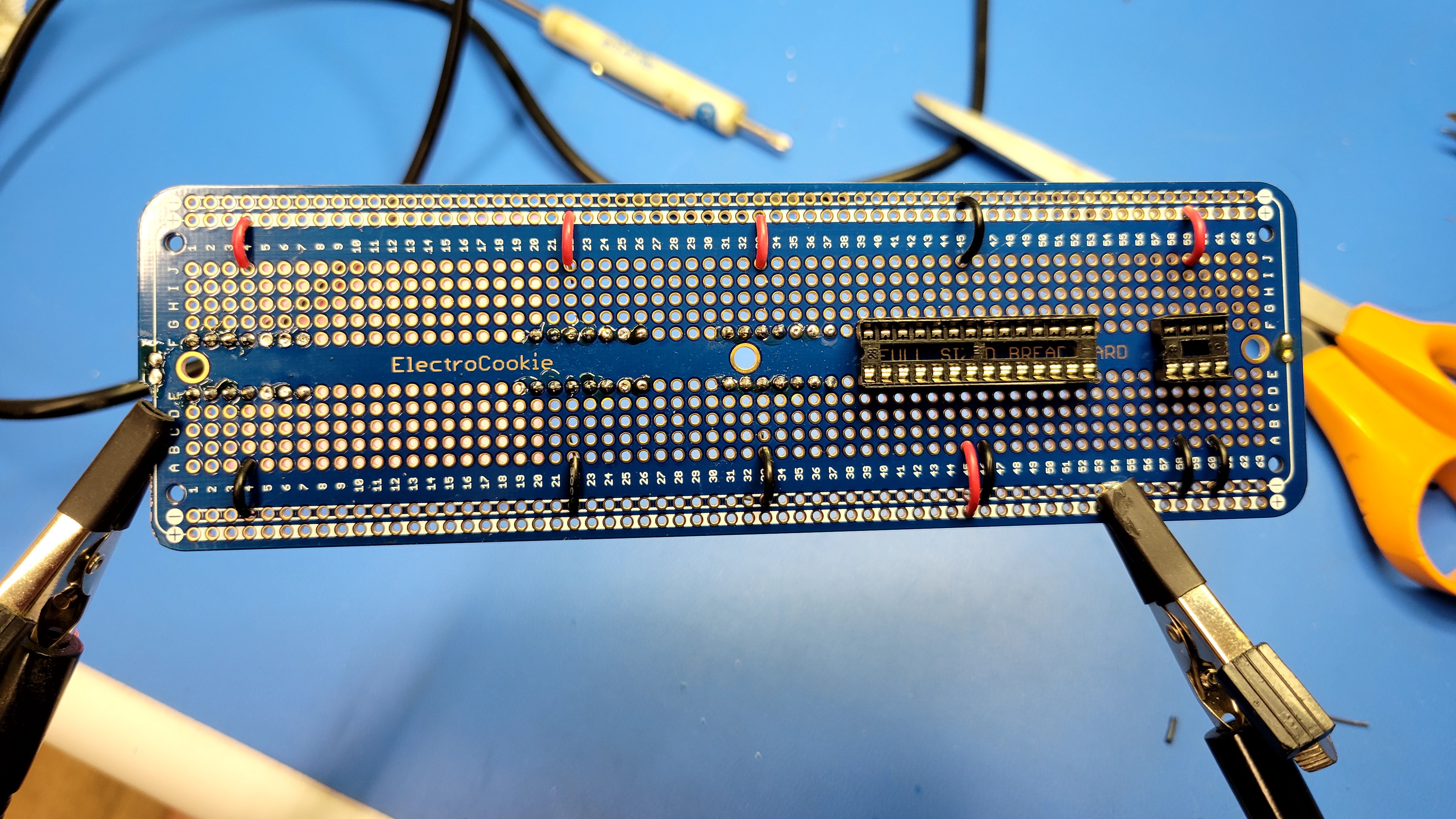
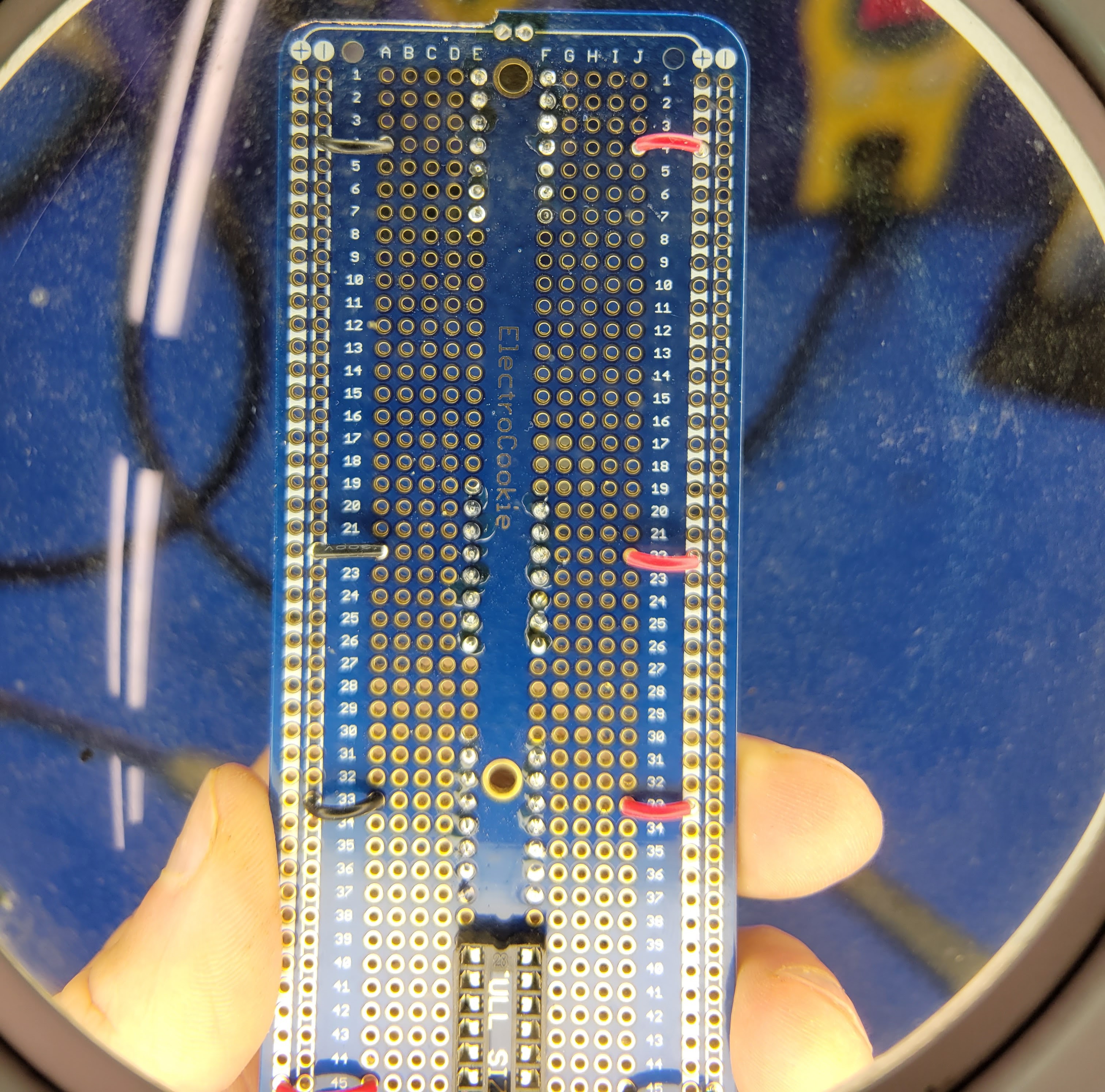
For the header connections, wire IC5 pin 4 (row 4), IC6 pin 5 (row 22), and IC7 pin 5 (row 33) to the 5v bus. Then wire IC5 pin 11 (row 4), IC6 pin 10 (row 22), and IC7 pin 10 (row 33) to the ground bus.
For the microcontroller and audio op amp sockets, wire microcontroller pin 7 (row 45) and audio op amp pin 6 (row 59) to 5v bus. Then wire microcontroller pin 8 (row 46), microconroller pin 22 (row 45), audio op amp pin 2 (row 58), and audio op amp pin 4 (row 60) to the ground bus.
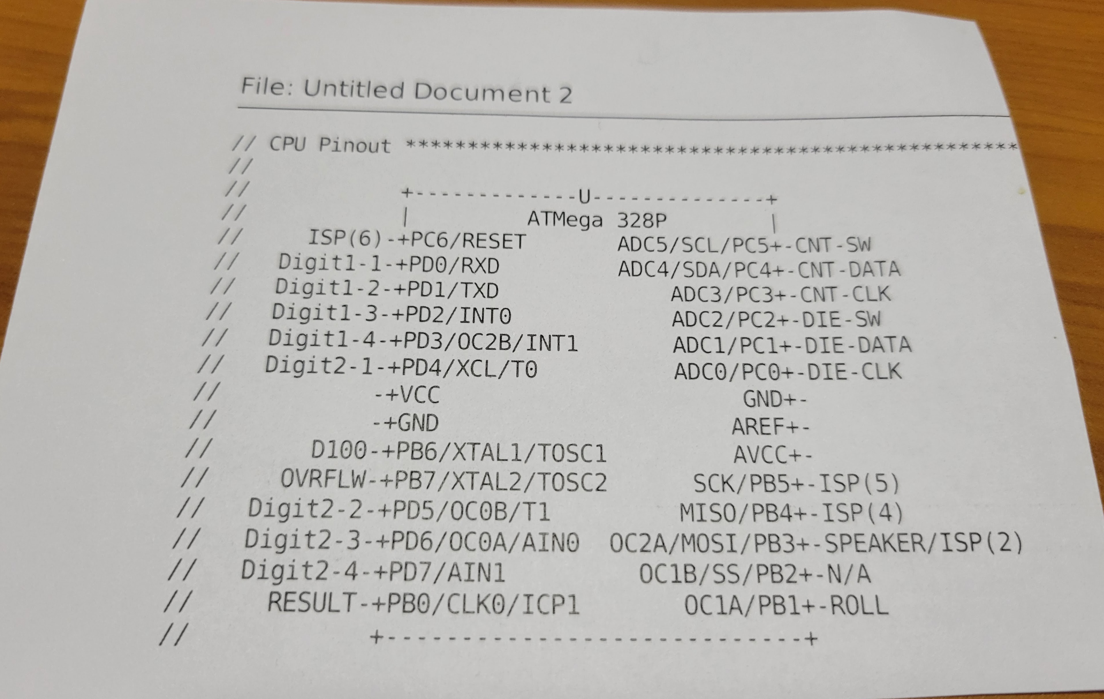
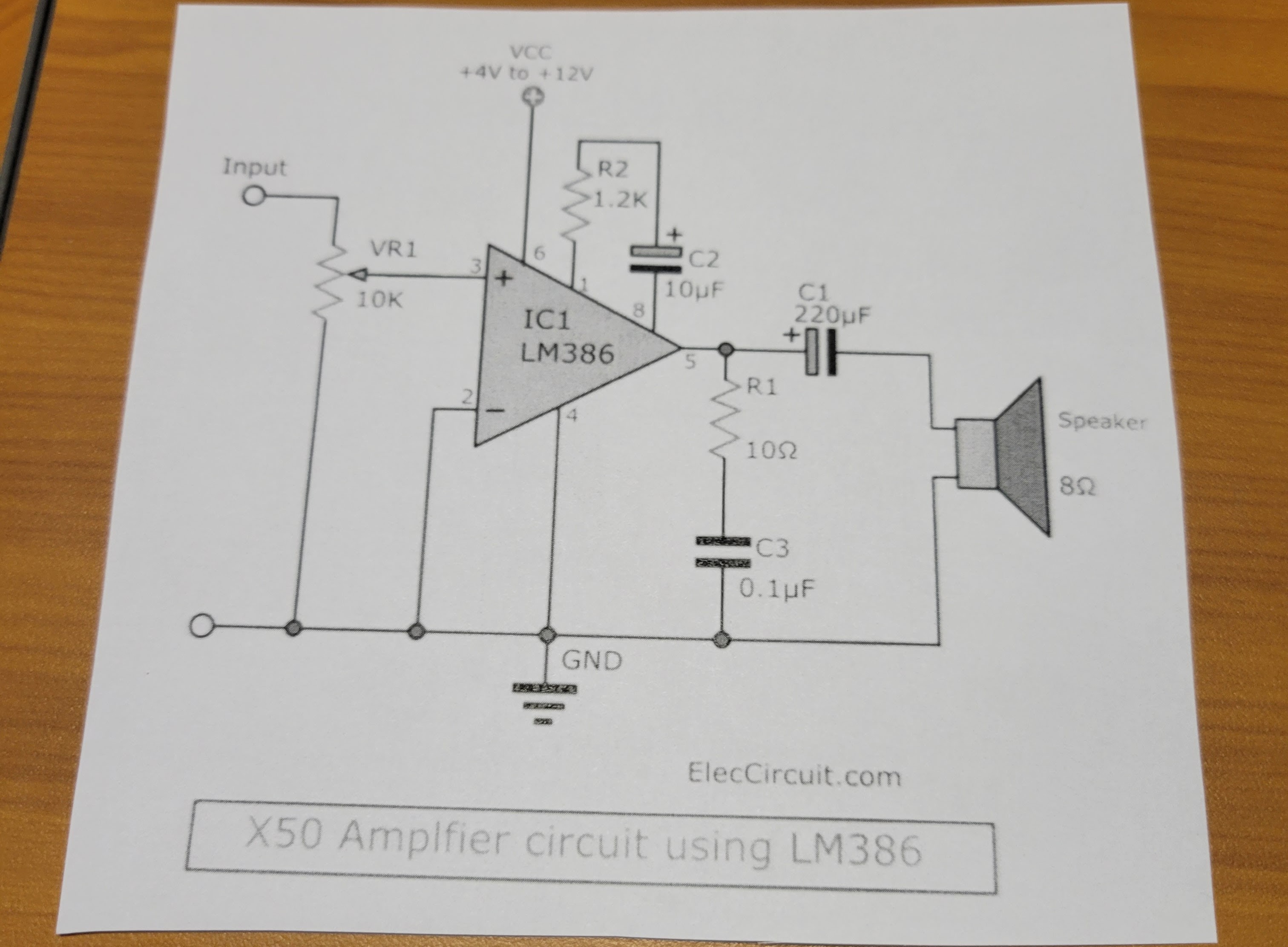
Tip: I print out the pin out for the microcontroller cut it out and post it on my work bench with a magnet so I can reference it easily. You can find this pin out in the comments in the main.c file in the source code I provide (B-H_DiceTower_v3.zip). I do the same for any other circuits I might be wiring up. In this case, I printed out the simple amplifier circuit for the LM386 op amp I am using.
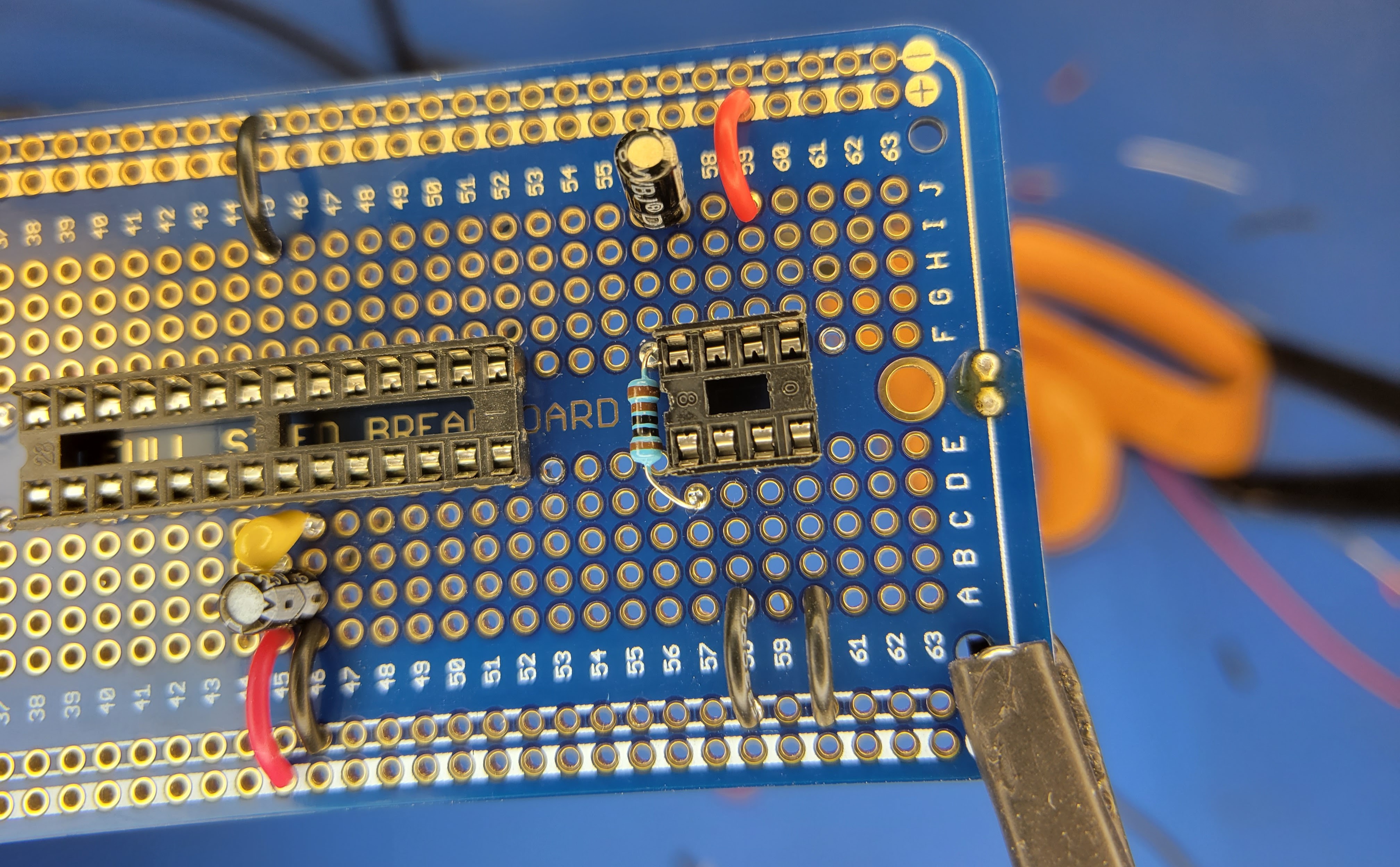
Next, wire up the decoupling caps on Vcc and ground going to the microcontroller. These will filter out noise coming from the power supply. These are the 10 uF electrolytic capacitor and 0.1 uF ceramic capacitor documented in the BOM log. They will be soldered between pin 7 (row 45) and pin 8 (row 46). When soldering in the electrolytic capacitor pay attention to the polarity. You will need to connect the negative lead to ground (pin 8 on the microcontroller). Note: I later added a 10uF decoupling capacitor to the power pin (pin 6, row 59) of the audio amp IC. This reduced the noise in the audio circuit.
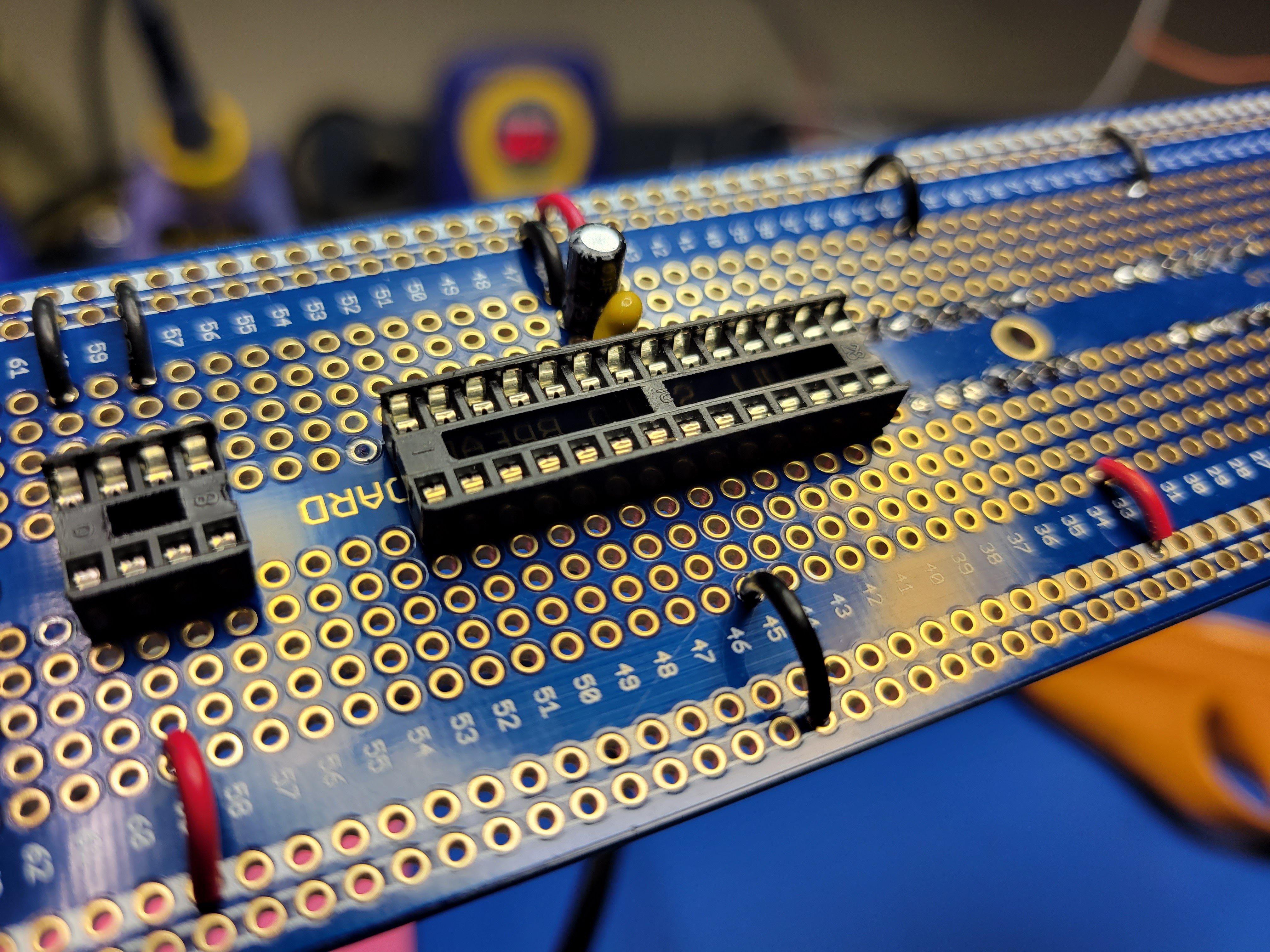
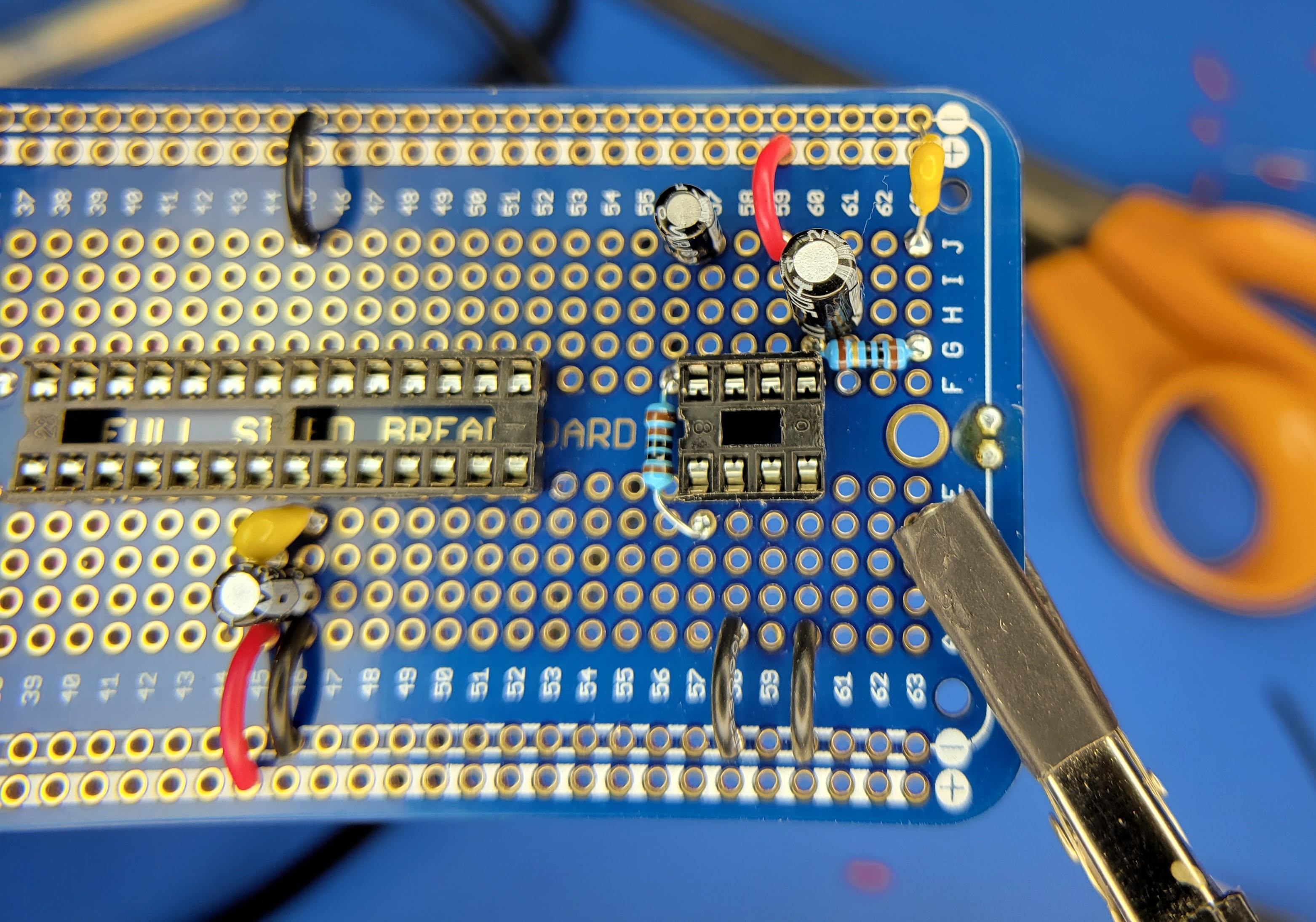
Next start wiring up the audio circuit. First wire up the feedback for the amplifier gain. This requires the 10 uF electrolytic capacitor and 1K Ohm resistor from the BOM. Again pay attention to the polarity of the capacitor. The negative lead should be soldered to pin 8 (row 57) and the other lead with be soldered to row 56. Then the 1K Ohm capacitor will be soldered from the same row 56 to pin 1 (row 57) of the op amp. Note: The 1K Ohm capacitor provides about 40x gain. I found this to be a little quiet with the cheap LM386 ICs I purchased. So, I soldered a jumper wire from row 56 to pin 1 (row 57). This bypassed the 1K resistor and provide 200x gain. Sound was better. If you use a reputable LM386-1 IC you may or may not need to do this. It also will depend on the speaker you select. A 4 ohm speaker will be louder than an 8 ohm speaker.
Next wire up the output filter. This requires the 10 Ohm resistor, 0.1 uF ceramic capacitor, and 220 uF electrolytic capacitor. Solder the 220 uF electrolytic capacitor positive lead to pin 5 (row 60). The negative lead will solder to row 61. This row will be the positive (+) output to the speaker when it is wired up later. Solder the 10 Ohm resistor from pin 5 (row 60) row 63. And finally, solder the 0.1 uF ceramic capacitor from row 63 to the ground bus.
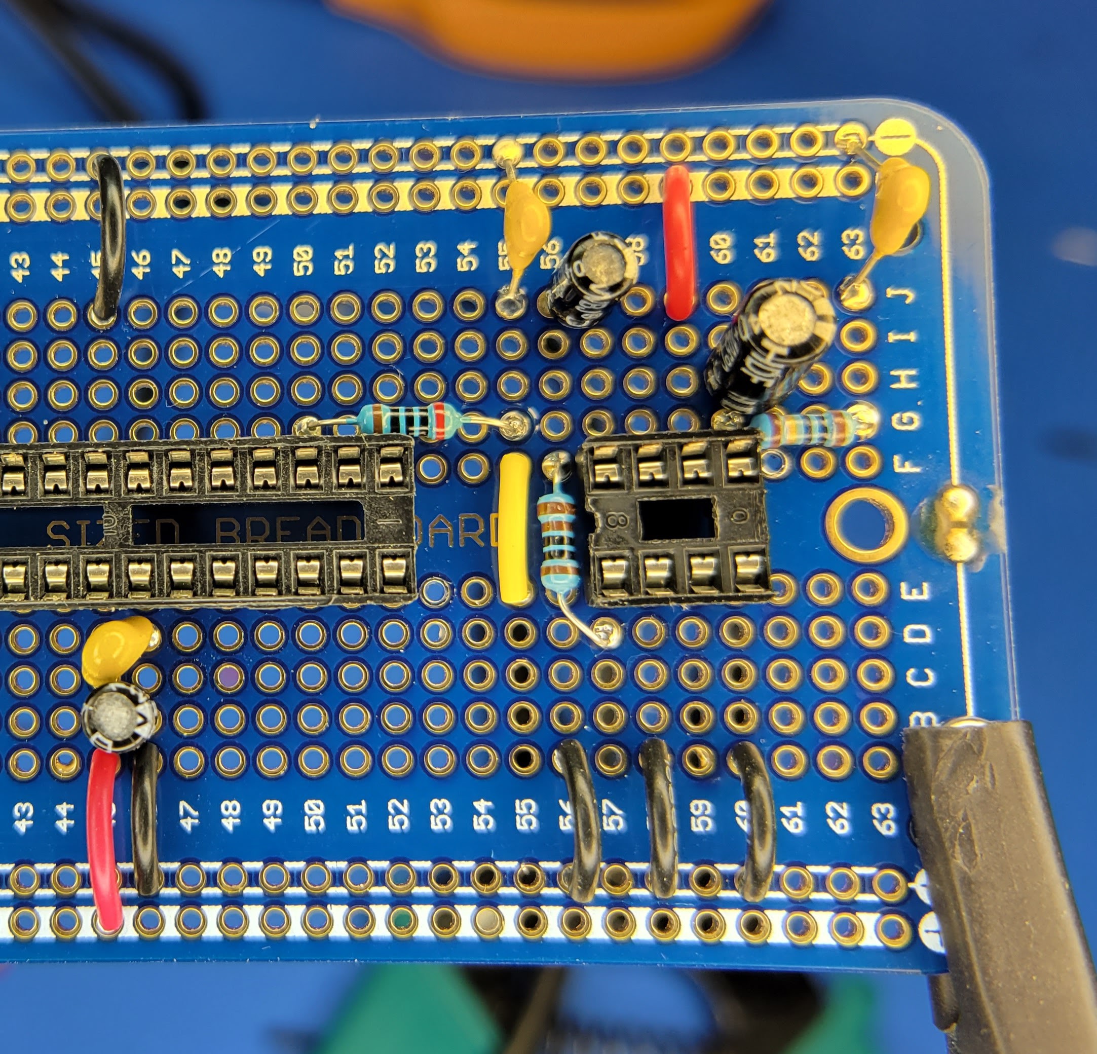
Next wire up the audio output from the microcontroller pin 17 (row 50) to the 10K Ohm potentiometer and the audio amp. This will include a RC low band pass filter to further reduce unwanted noise. Start by soldering the 200 Ohm resistor from pin 17 (row 50) to row 55. Then solder the 0.1 uF ceramic capacitor to row 55 and the ground bus. Next solder a jumper wire (yellow) between row 55 and row 55 on the other side of the protoboard. This will be the output to the "fixed end" of the potentiometer. Finally, solder another jumper wire from the ground bus to row 56 A-E side of the board. This will be the ground for the other "fixed side" of the potentiometer. The wiper for the potentiometer will be wired pin 3 (row 59) of the op amp. The potentiometer will be wired up in a later log post.
Now you have the power and audio portions of the controller board wired up. It's a good time to check your power from the PCB. Connect the controller board back to the PCB, plug in the meter, and turn it on. Do not insert the microcontroller or the op amp into the sockets at this time. Then check the DC voltage between pin 7 (row 45) and pin 8 (row 46) on the microcontroller socket. You should get something stable and close to 5v.
Next we will wire up the interface to the nixie tube drivers and the transistors that drive the 100 hundred digit and the overflow indicator.
Discussions
Become a Hackaday.io Member
Create an account to leave a comment. Already have an account? Log In.