 John Anderson
Now we'll apply graphics, install the controller, mount speaker, LED, and controls.
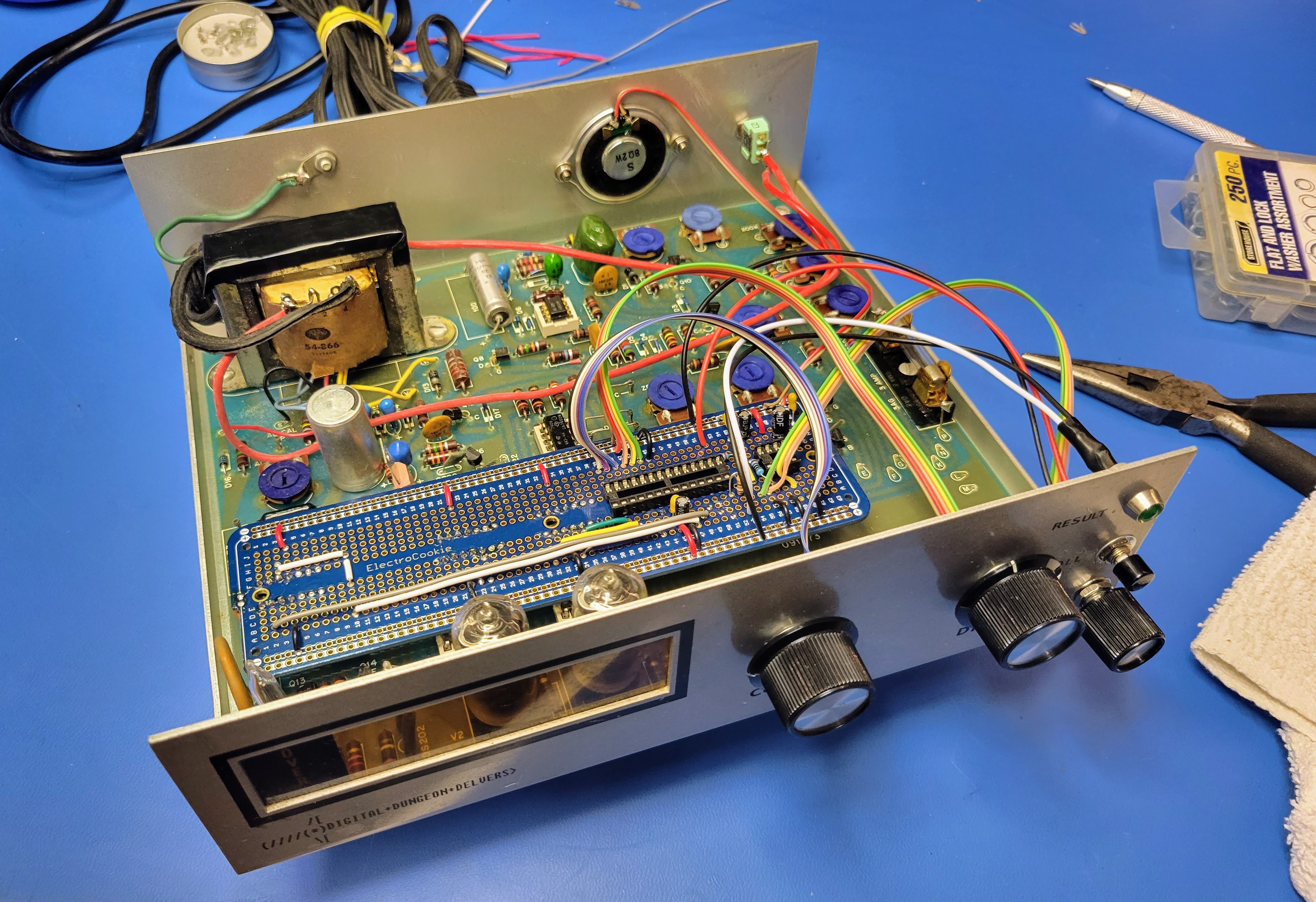
Start by installing the controller board back onto the PCB. Be careful to line up the header pins with the socket on the left. With that one lined up, the rest of the headers should line up as well. Lightly press the controller board into place. It won't take much pressure.
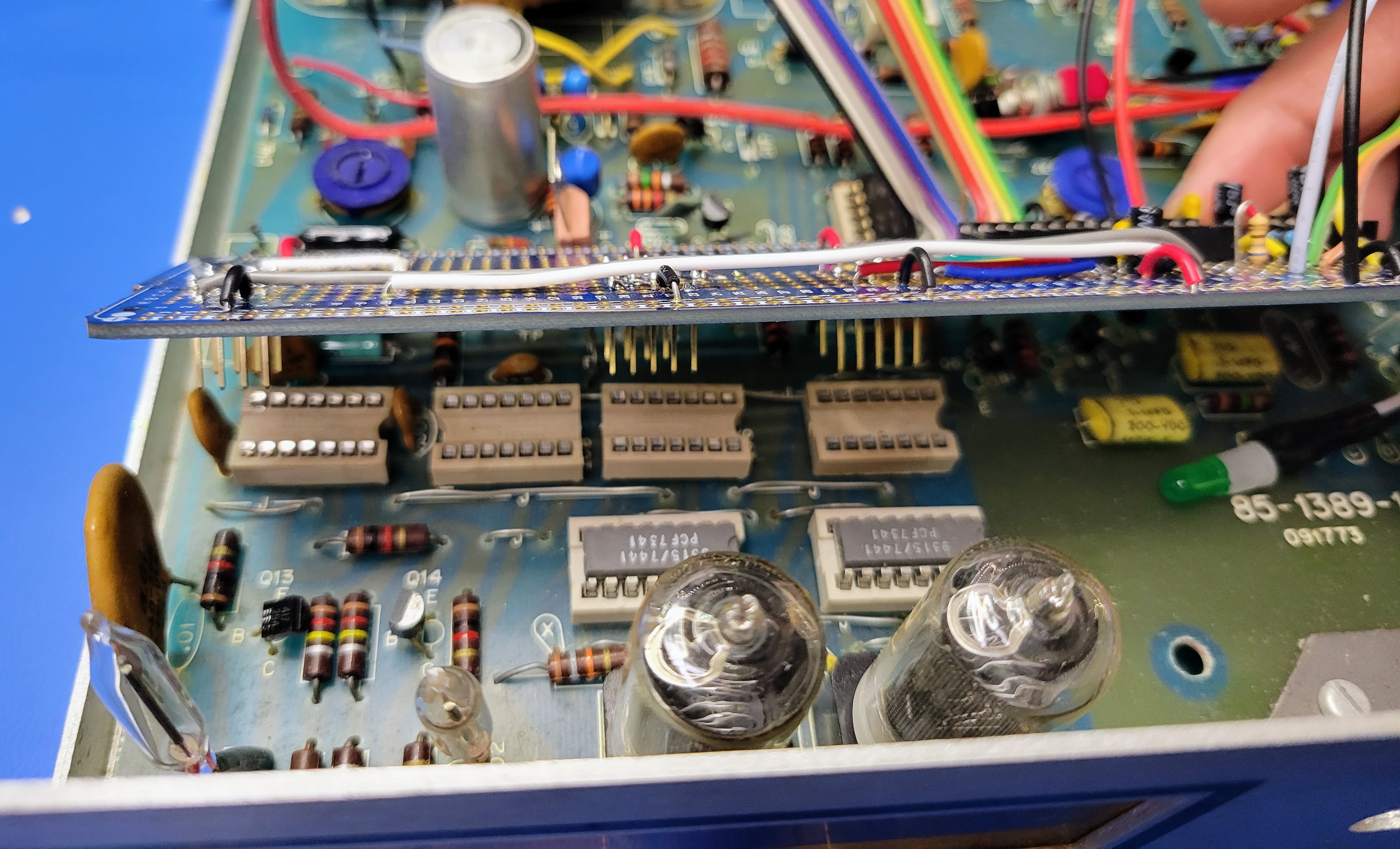
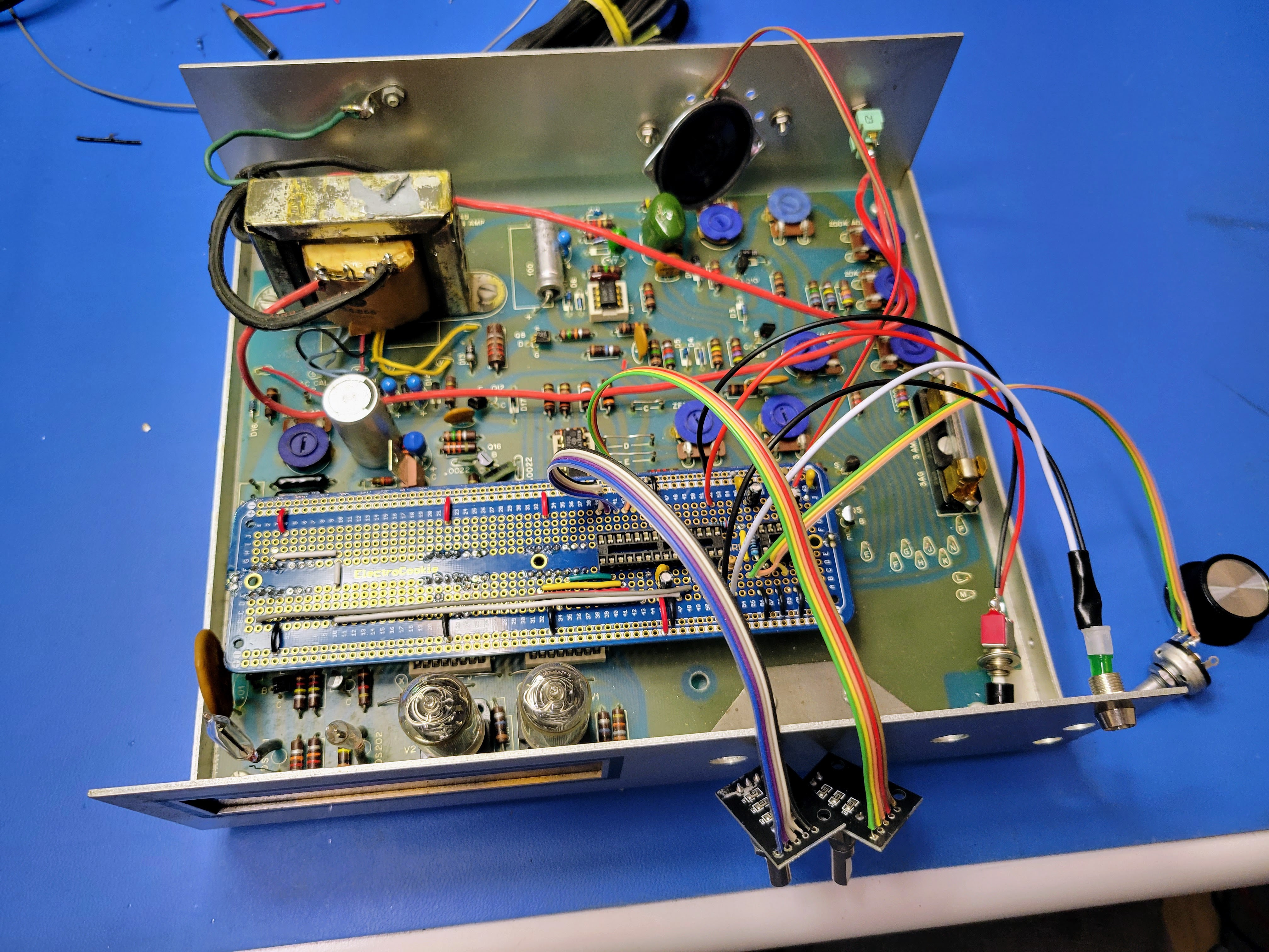
Once the controller board is in place, everything should look like this.
Next, mount the speaker to the holes drilled earlier. A stash of small screws, washers, and nuts is helpful here. I always keep all screws from disassembling other vintage electronics.
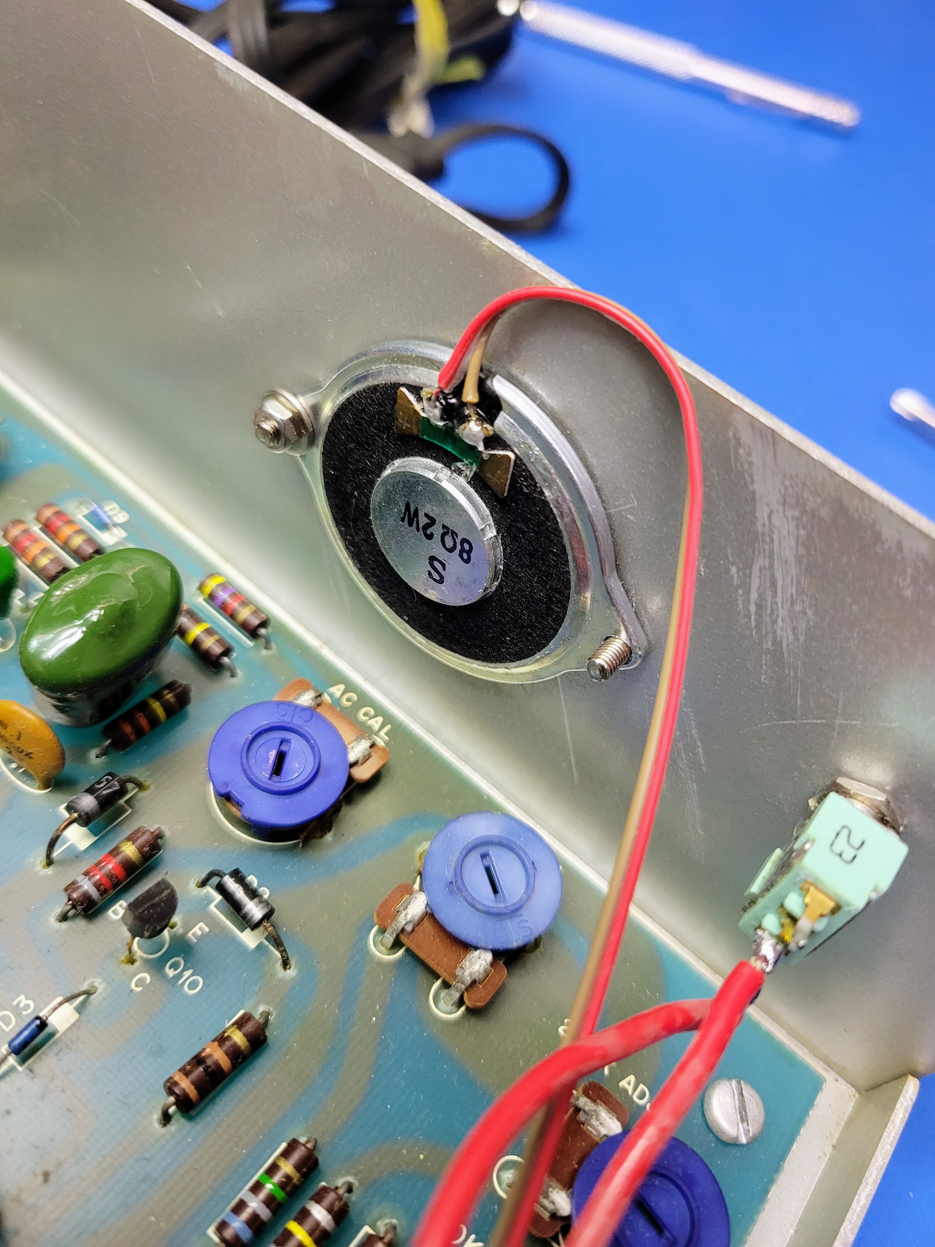
Use a pair of needle nose pliers and a screw driver to get these screws nice and tight. If they are loose you'll get some rattle in the voice/sound.
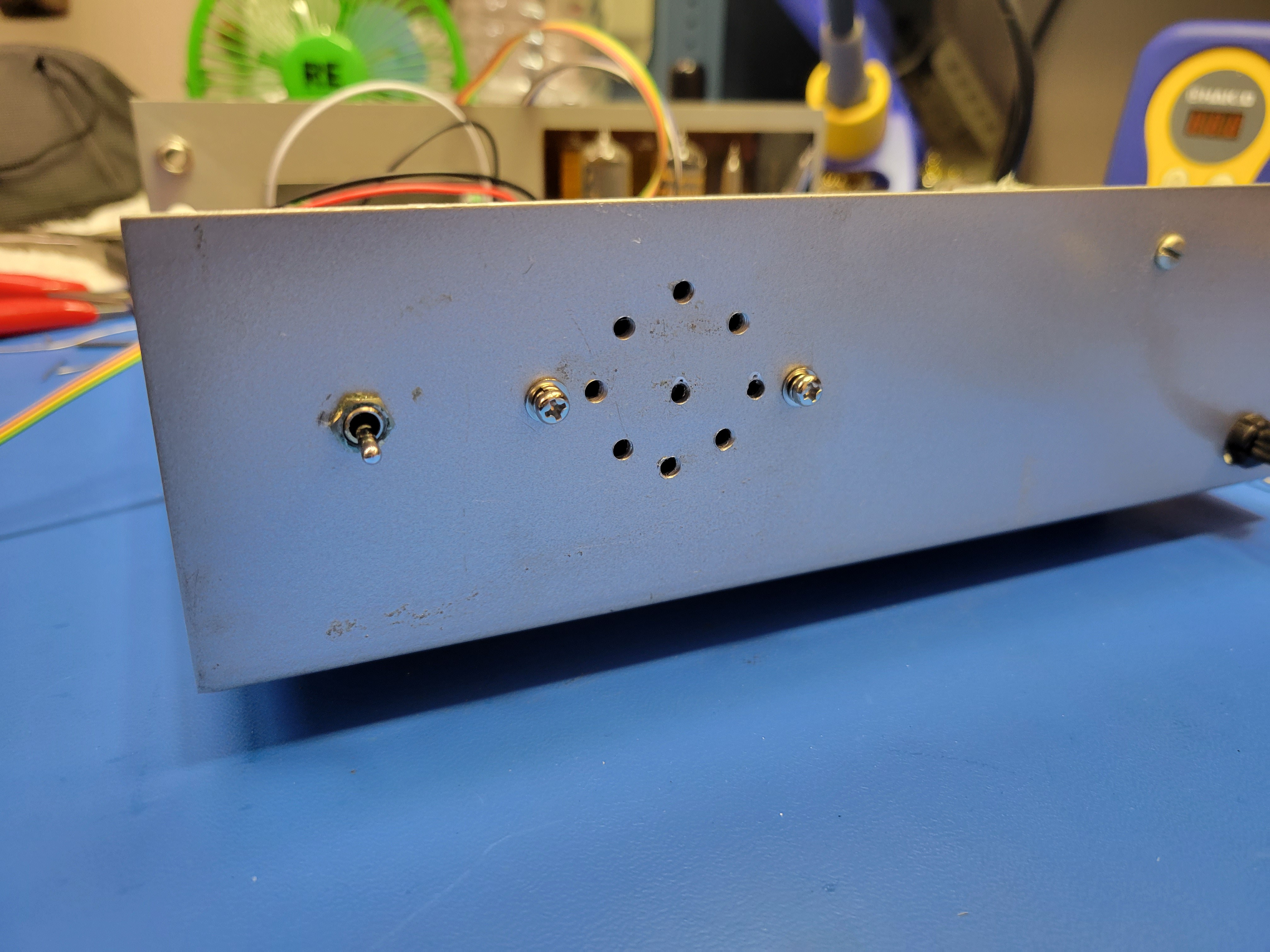
Once mounted, it should look something like this from the outside of the case.
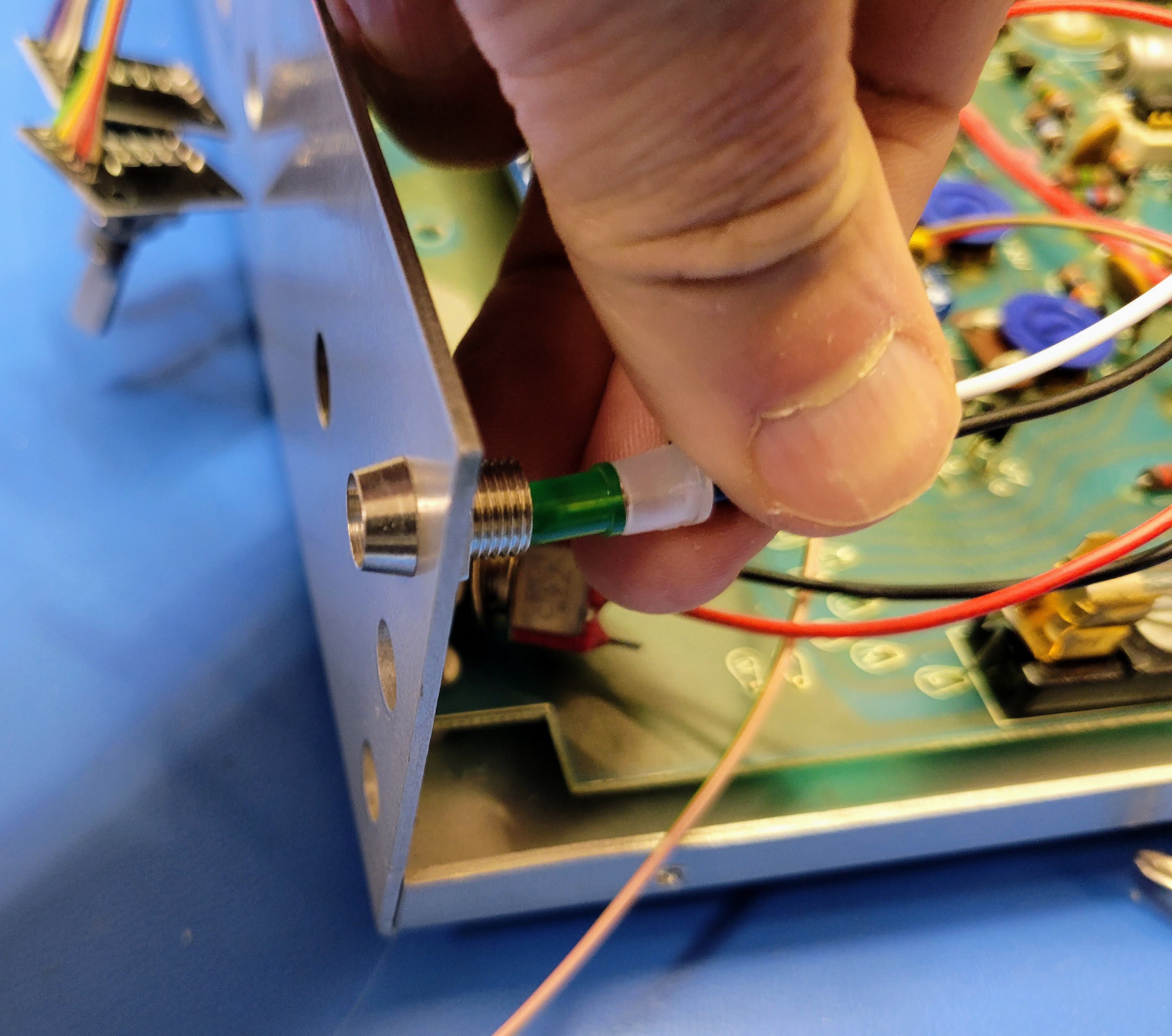
Next put the panel mount LED holder in the front panel and tighten it with the needle nose pliers.
The LED press into the holder from the back.
Then select some washers to space the roll button properly.
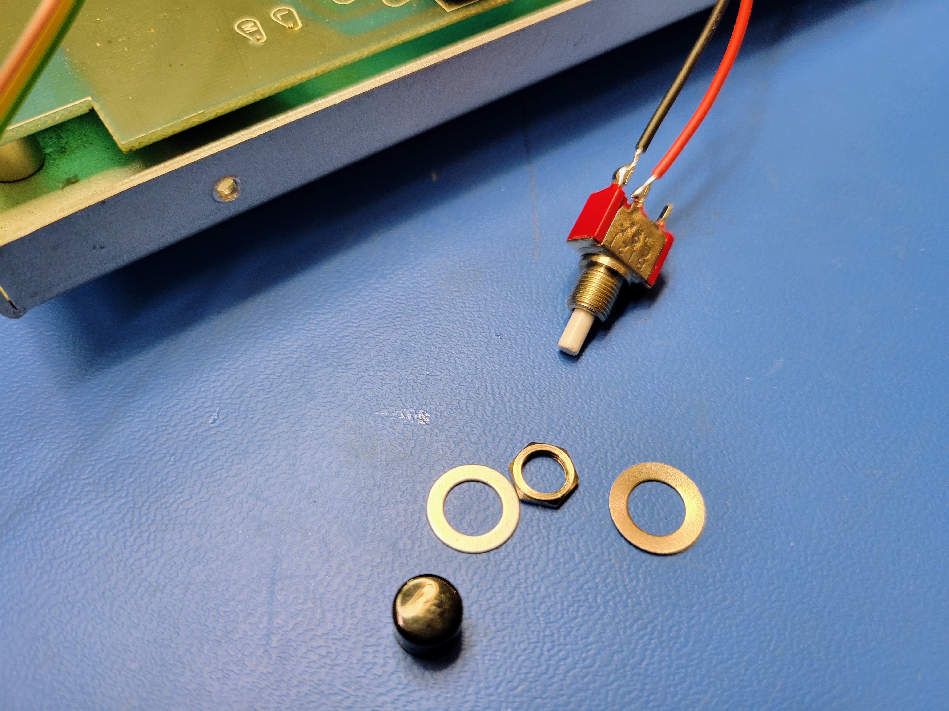
Then insert it into the front panel and tighten.
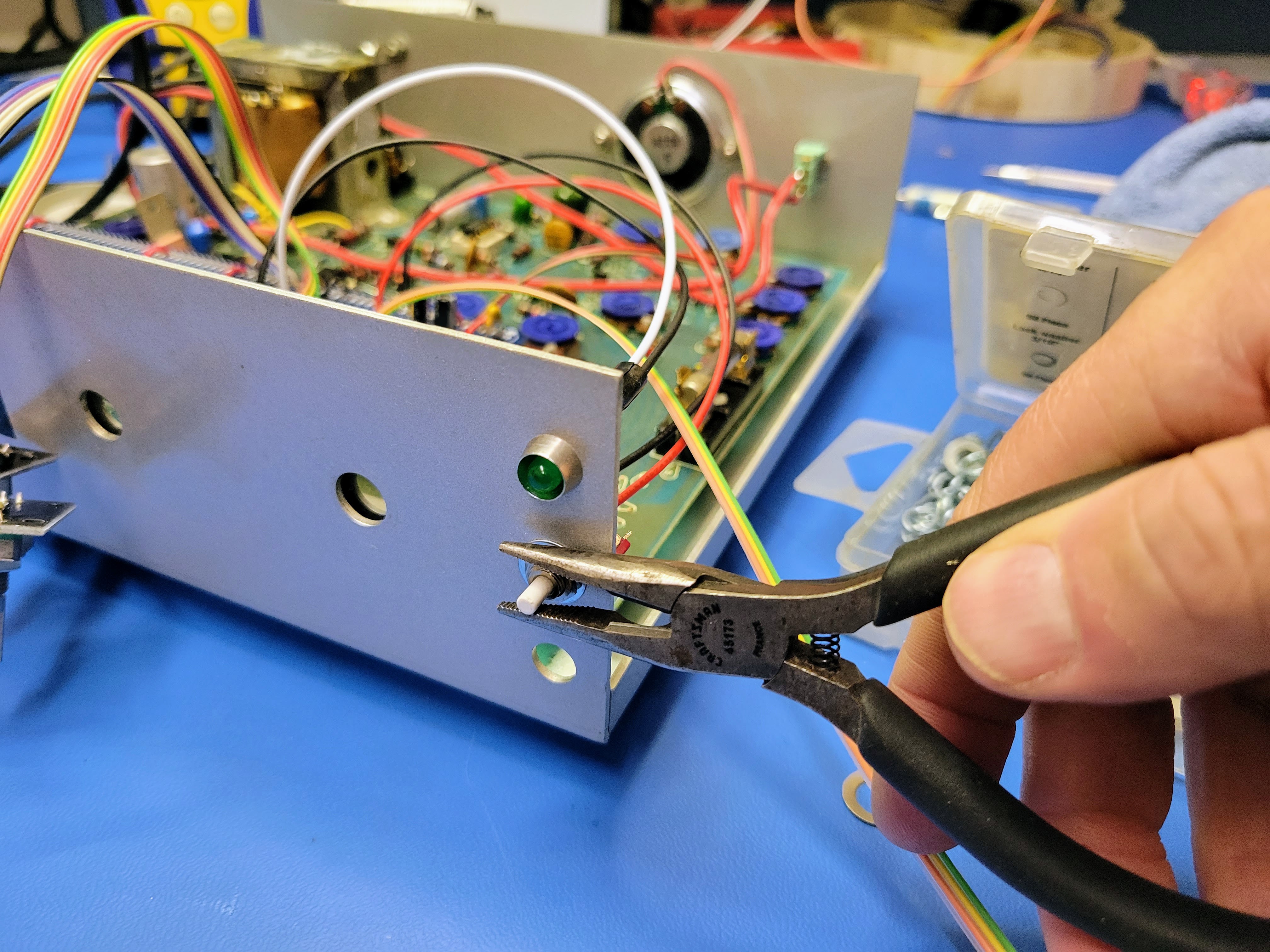
Next select the washers to set the volume pot knob appropriately.
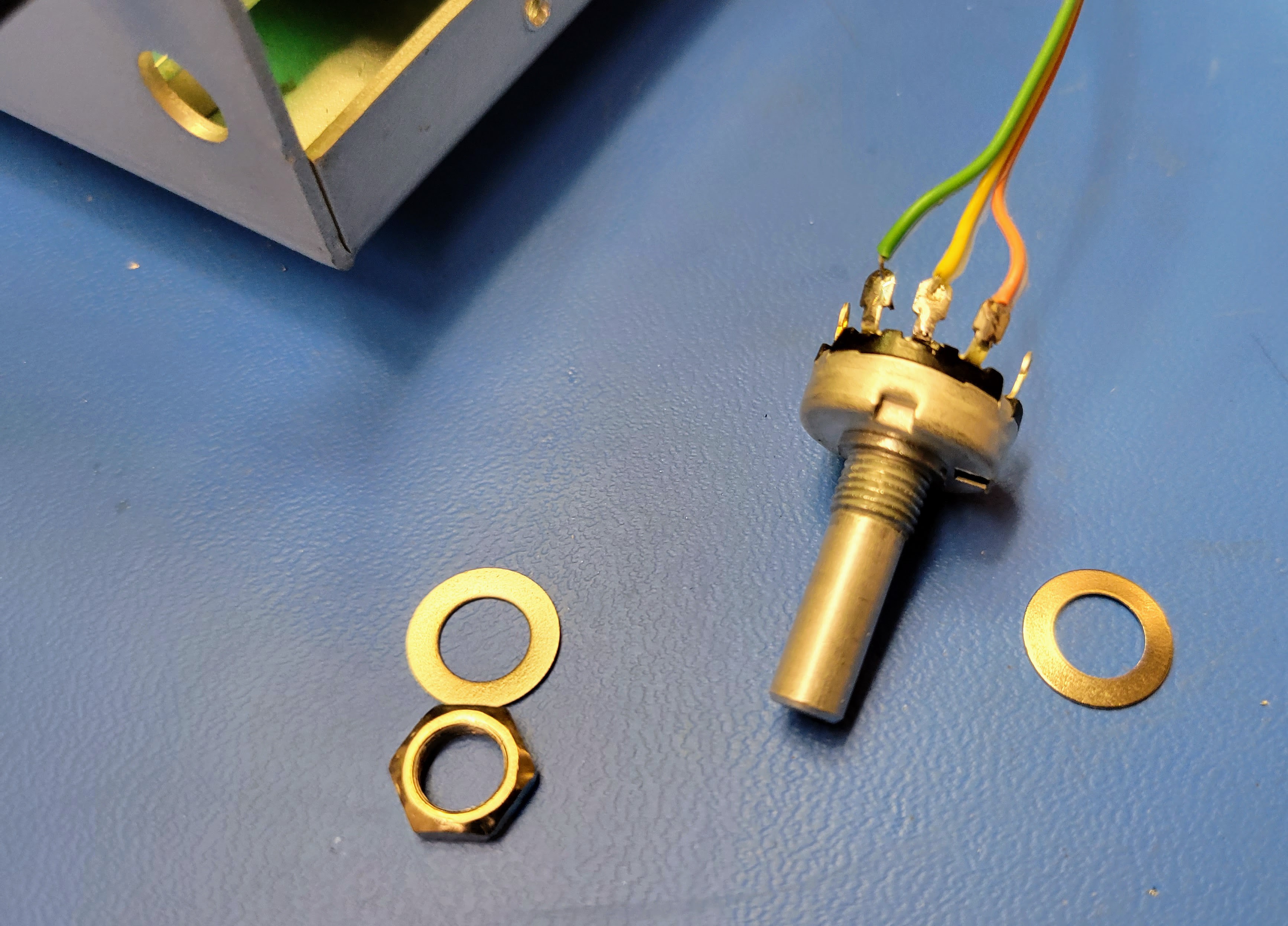
When you mount it, you will need to pay attention to it's orientation. This way low volume is on the left and high volume is on the right according to the knob indicator. Since the lugs will be very close to the metal chassis, I wrap the lugs/body in the single layer of electrical tape.
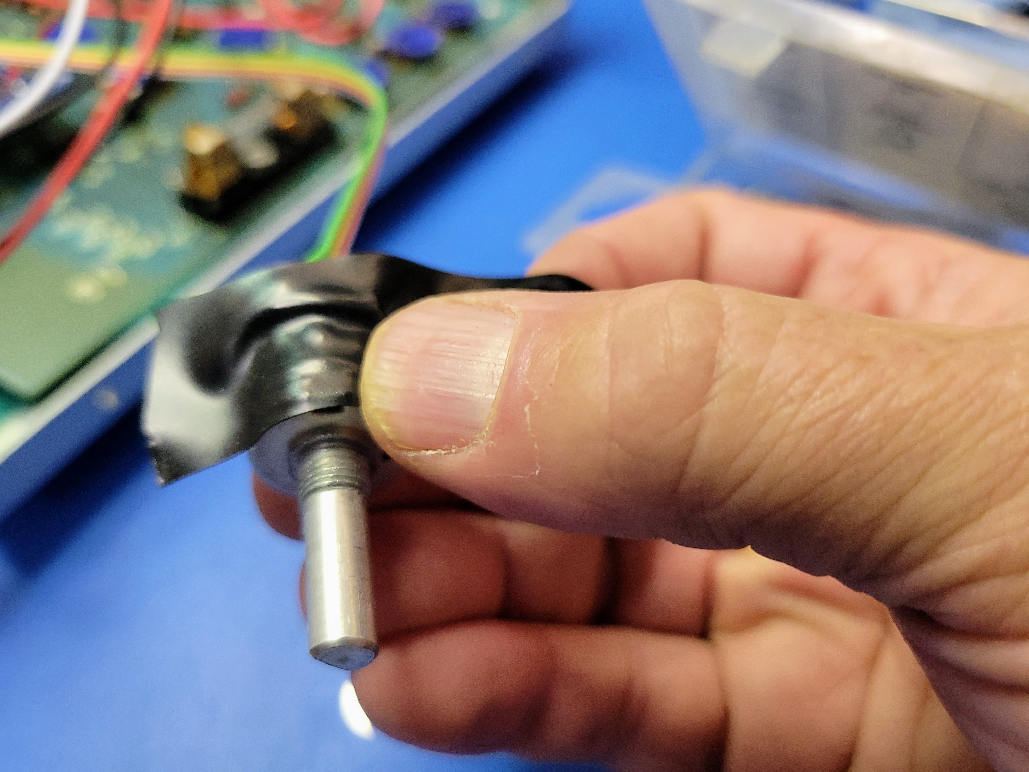
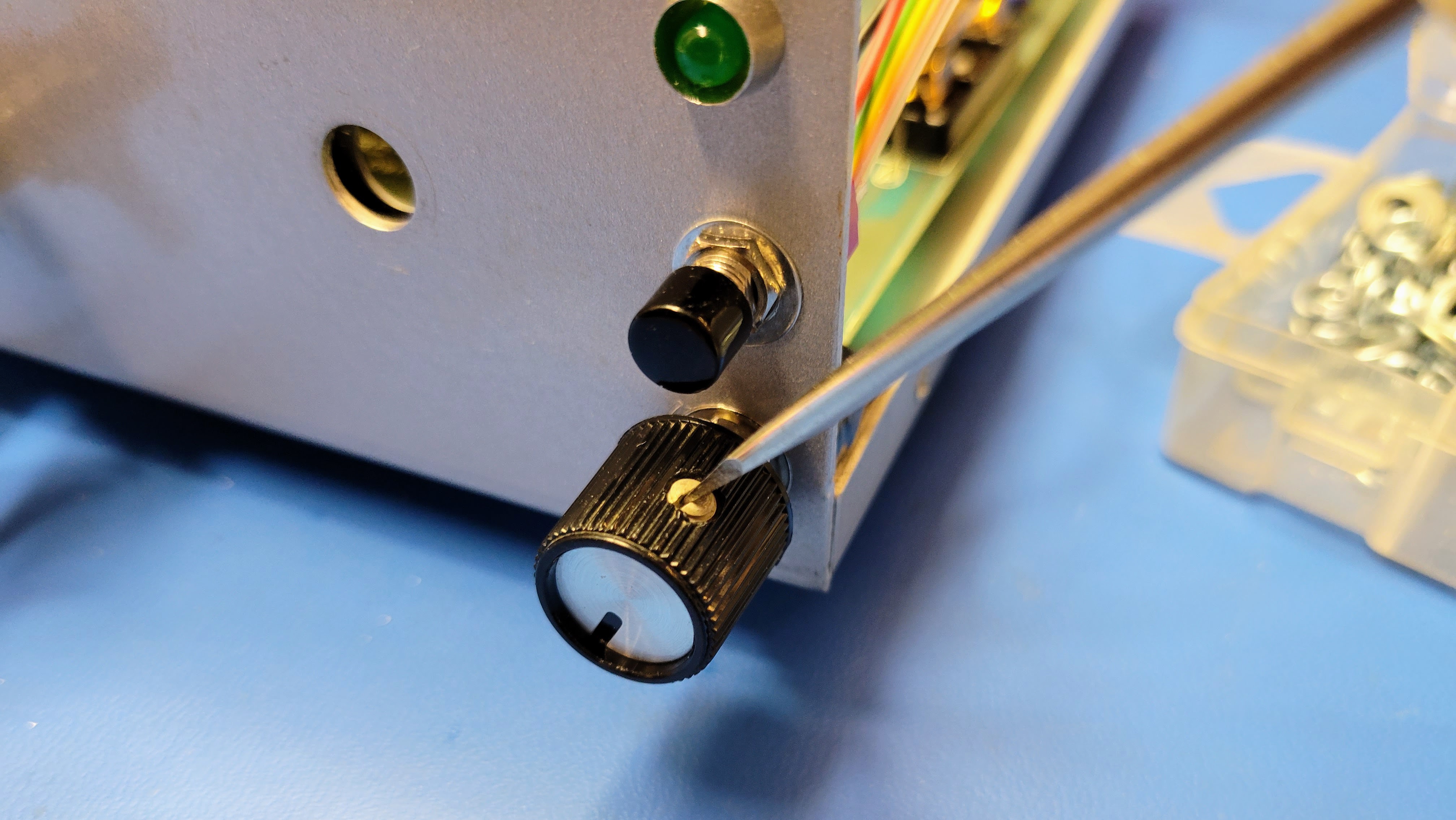
Insert the potentiometer into the front panel, double check it's orientation, tighten, and mount the knob. In this case, the knob has a flat head set screw.
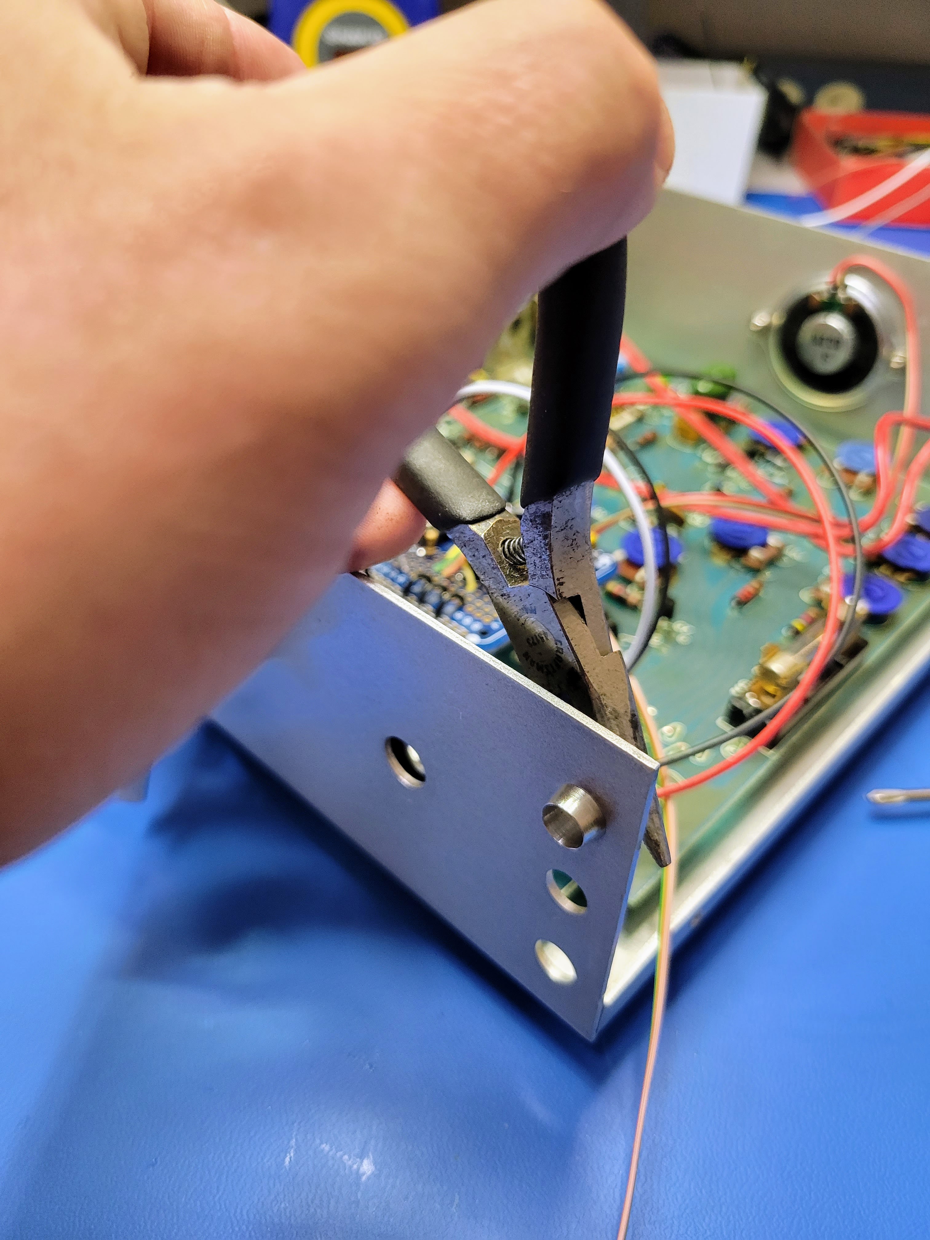
Then check out the rotary encoders. They often have a tab the keeps them from spinning in the panel. I just bend this tab back with a pair of, you guessed it, needle nose pliers.
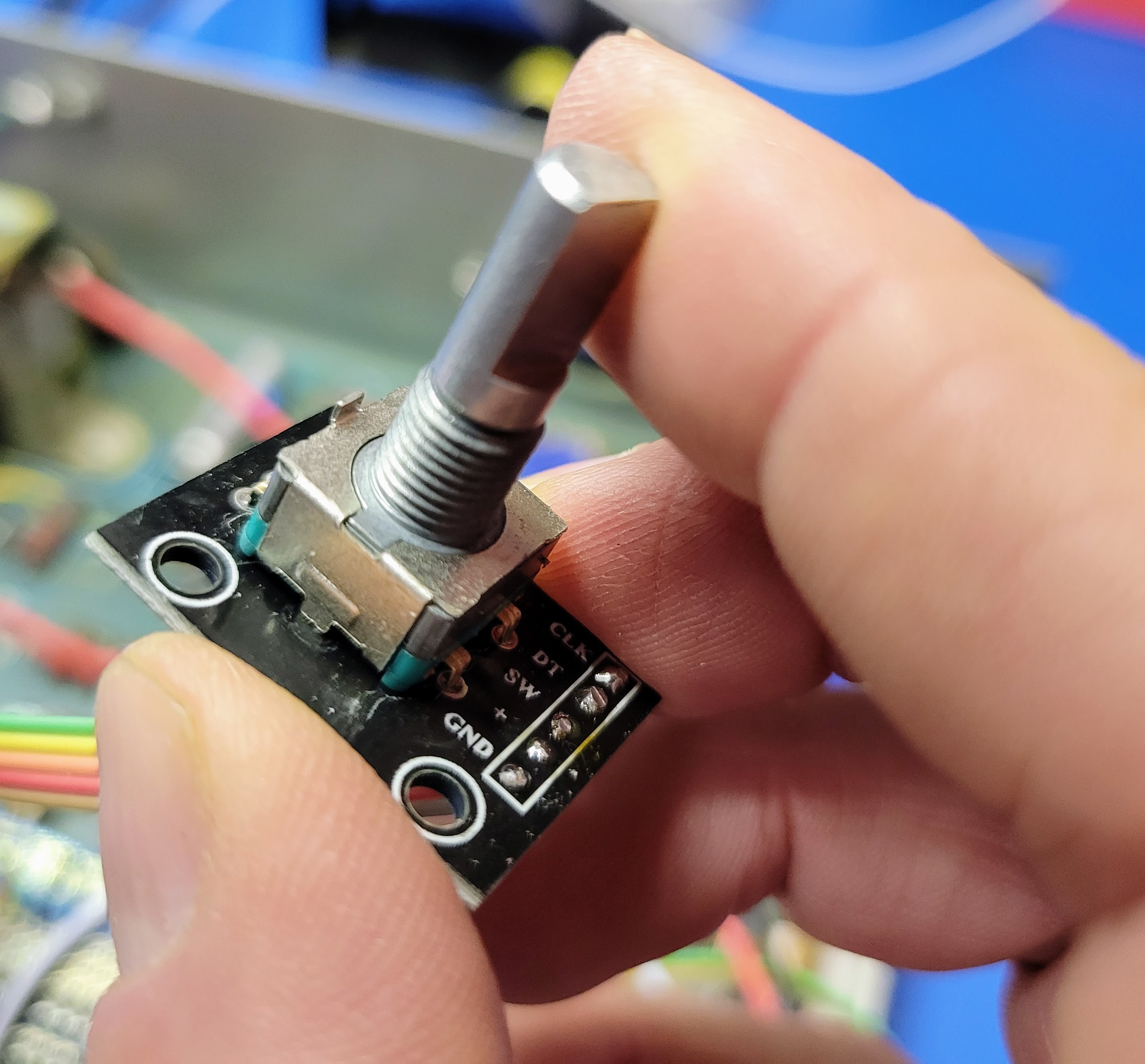
The encoders insert through the angle bracket that's screwed to the PCB. This holds everything square. To be honest, it's a little overkill for these encoders. The torque required to turn them is far less than the original rotary switched. So, it's an option to remove the angle bracket if it troublesome.
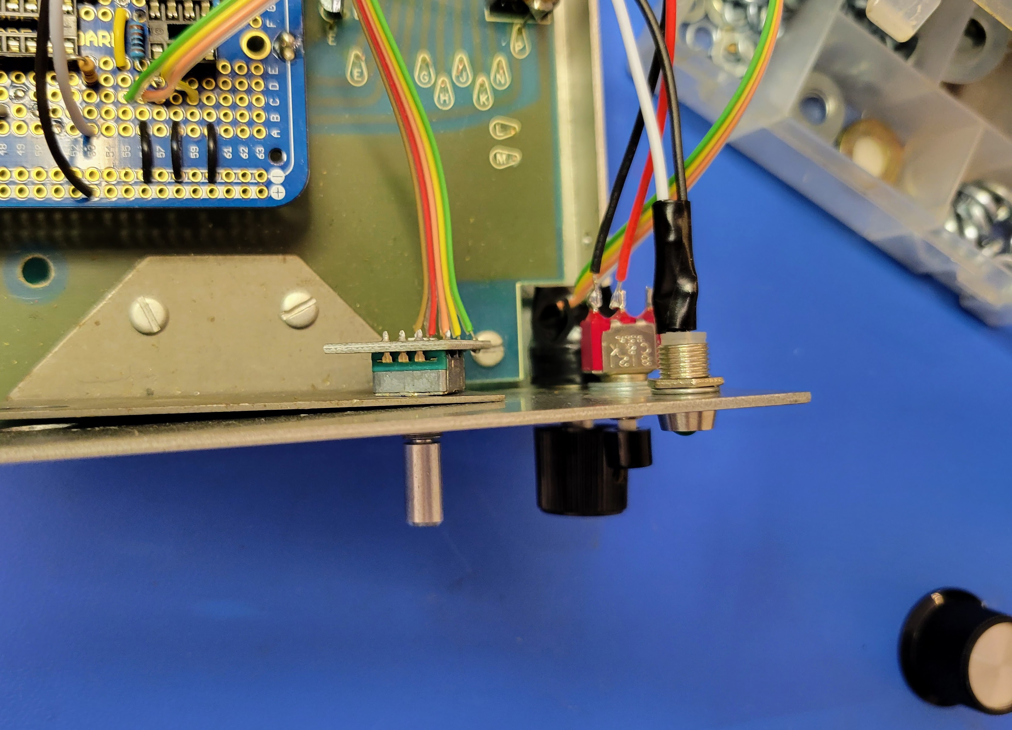
If you use the bracket, no washers are required on the back side to space the knob appropriately. Tighten up the encoders with my favorite tool.
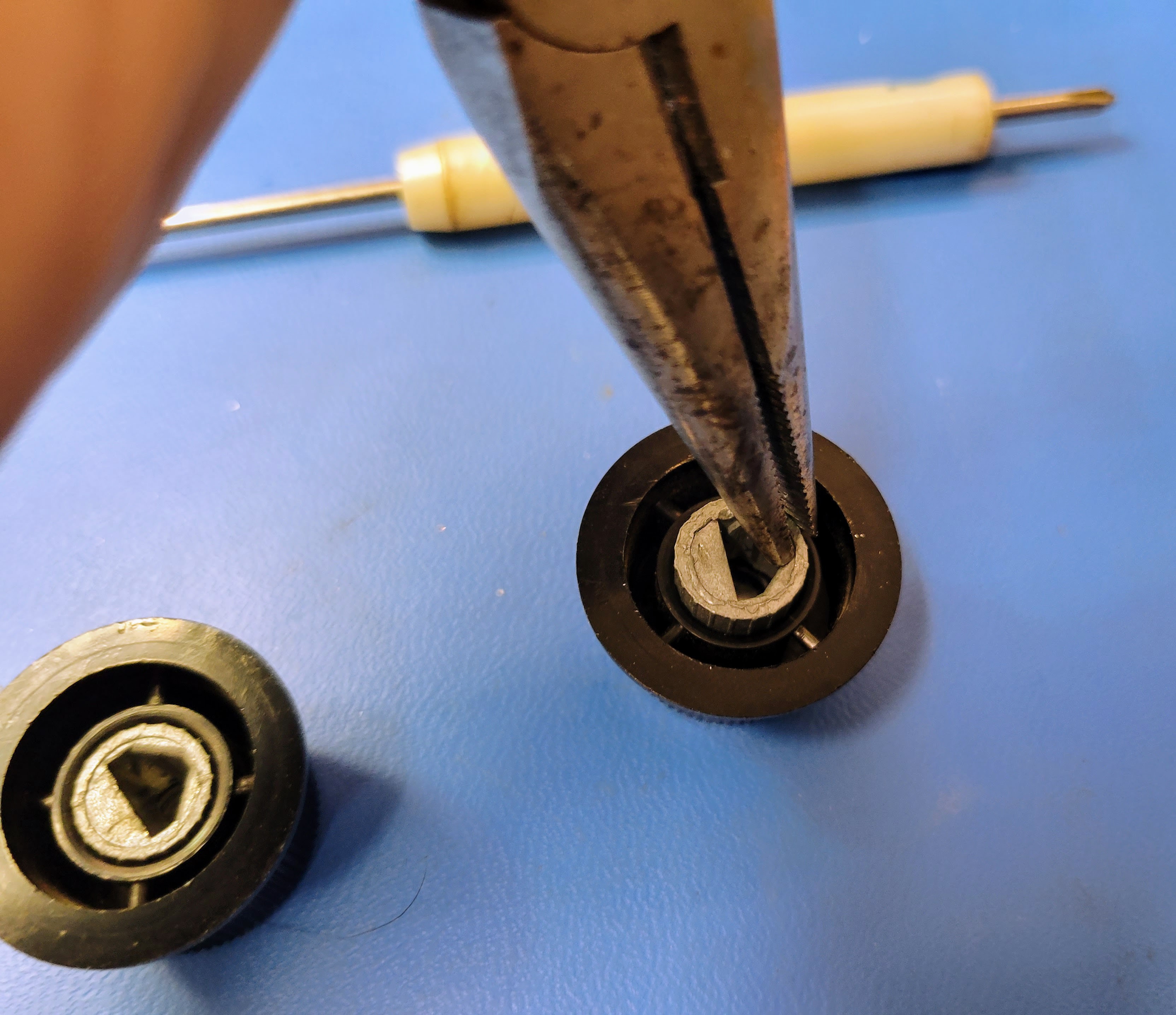
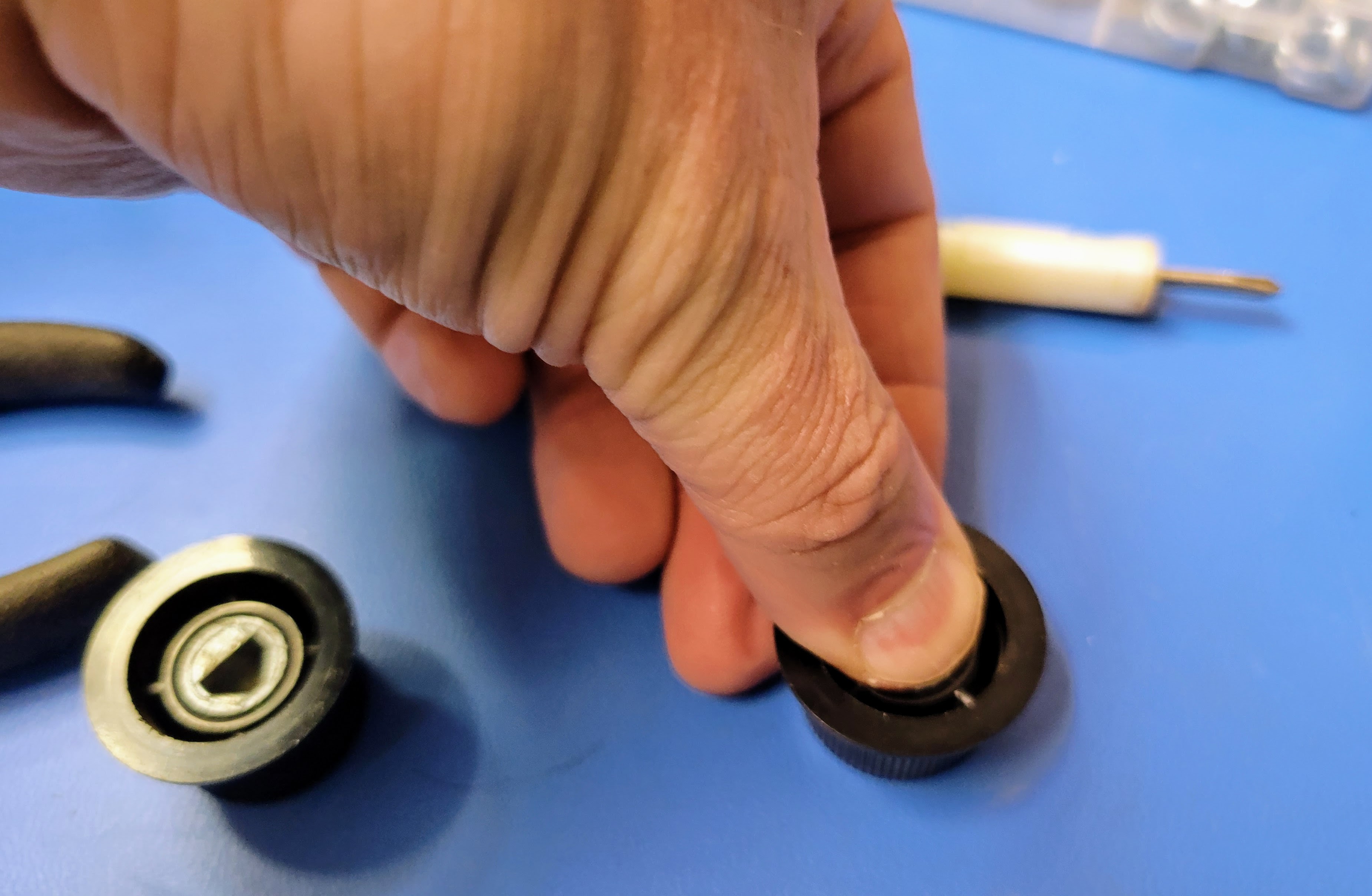
I like to use a variety of knobs on my builds. In this build, I reused the original knobs from the rotary switches. They don't have set screws. They have an interference fit instead. To create this fit, they have a thin piece of spring steel wedged into the pot metal inserts. Using a small screw driver, you can pry the spring steel up and grab it with the trusty needle nose pliers. With a little effort, you can pull it out. Frequently, the pot metal insert will pull out of the knob while doing this. Once the spring steel is out, you can simply press the pot metal insert back into the knob with your thumb.
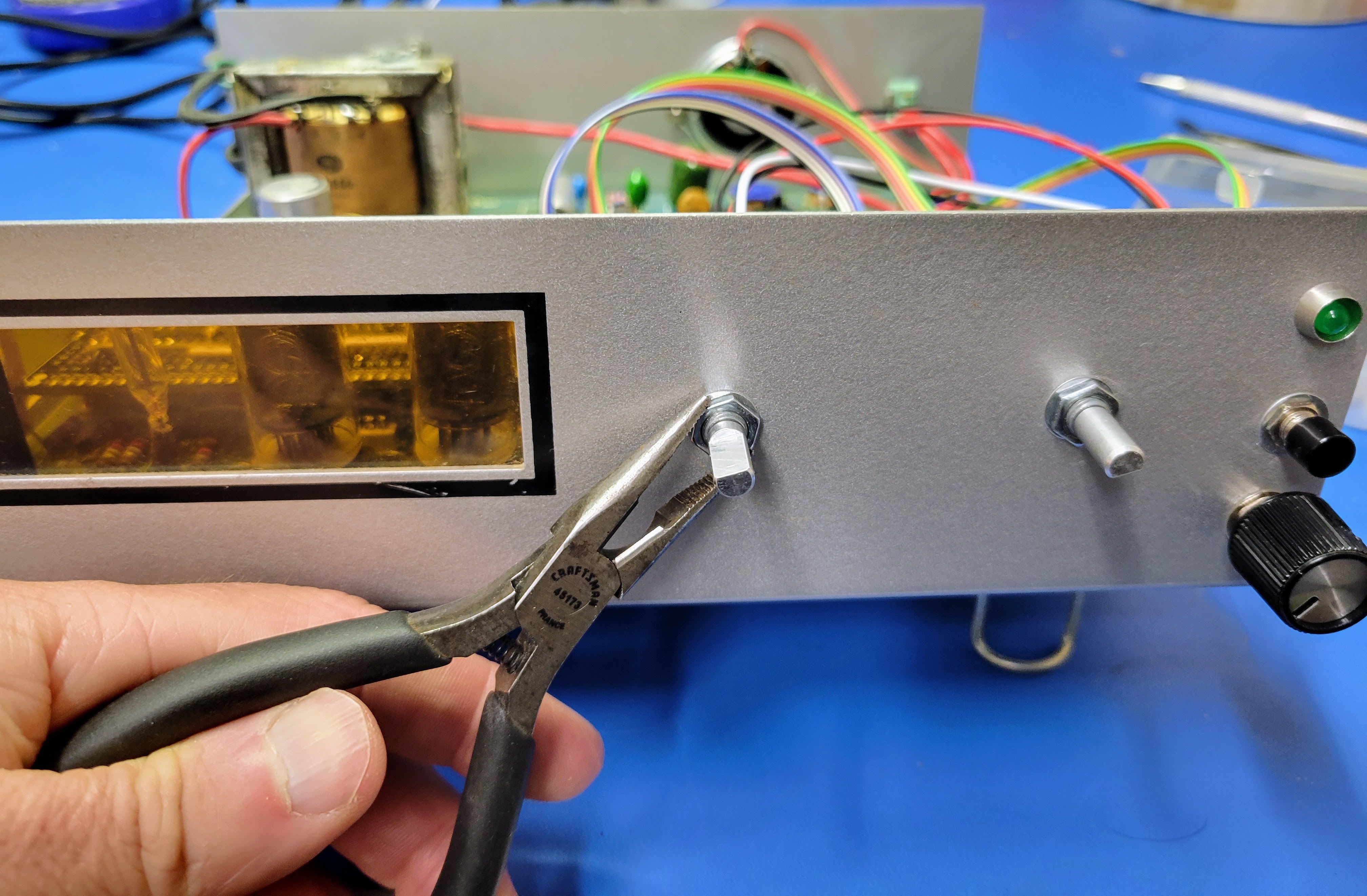
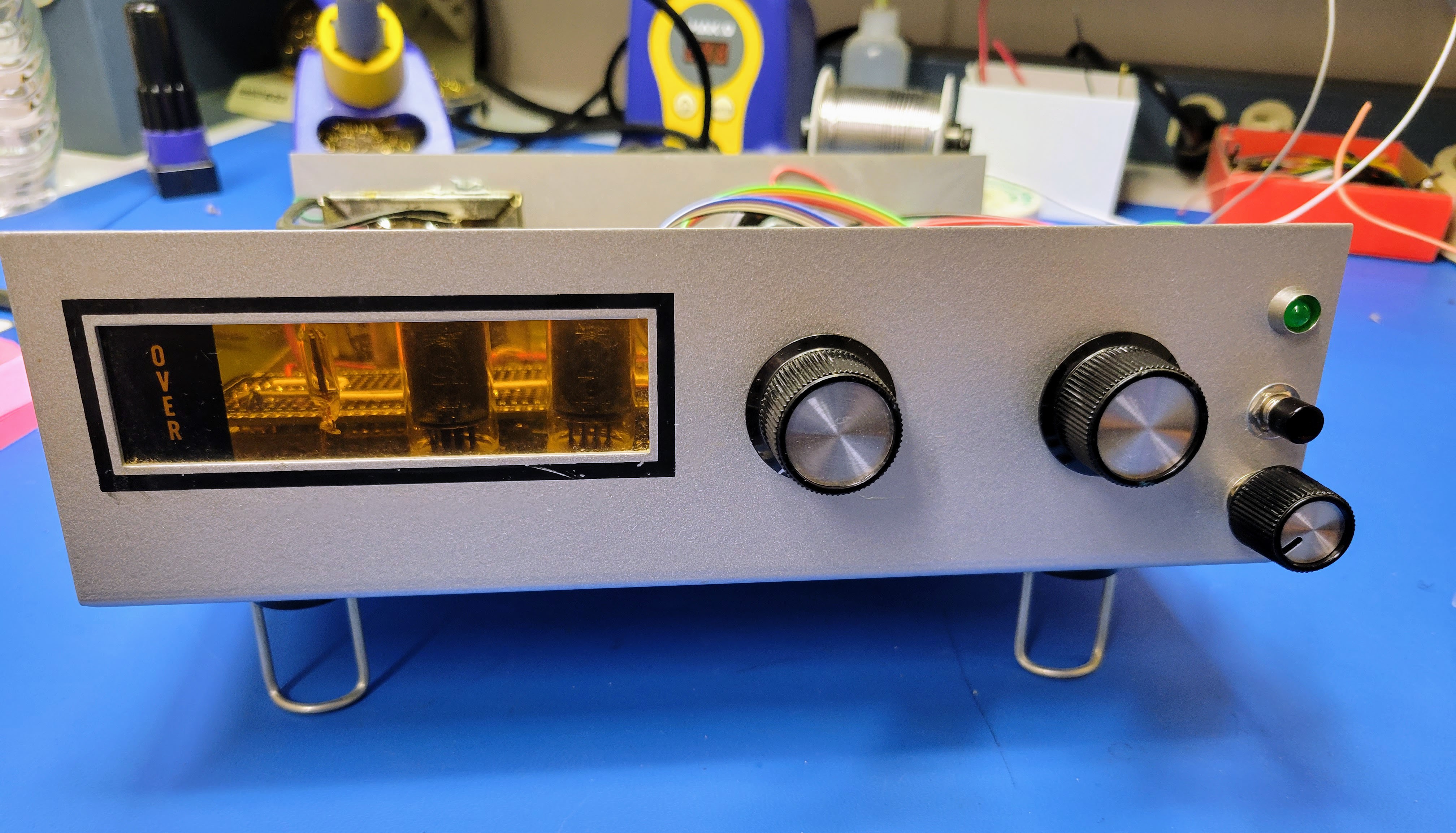
Since there is no set screw, the knobs will have a loose fit. A single drop of super glue is enough to hold them in place. However, I suggest doing that very last after you have proven that everything is working the MCU programmed and in place. We'll do that in the next blog. At this point, your face plate should look something like this.
For this build I am going with graphics that appear silk screened to the face plate like the original graphics. To get this effect without a lot of effort, I like you use laser printer compatible water slide decals. Just design the graphics you want your PC, print them on the water slide "paper", and put them on the face plate. I have been using these water slide decal papers. They seem to work reasonably.
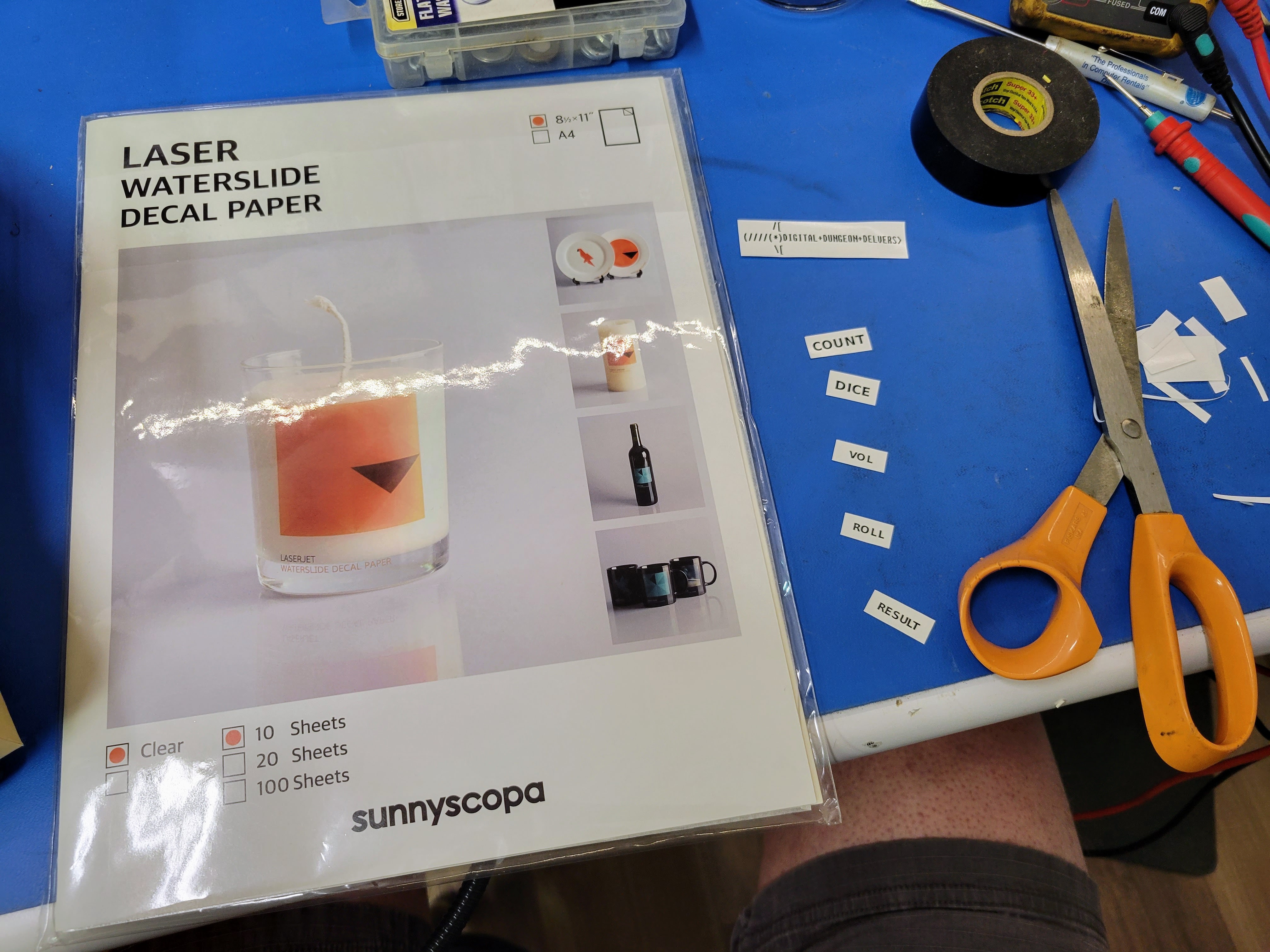
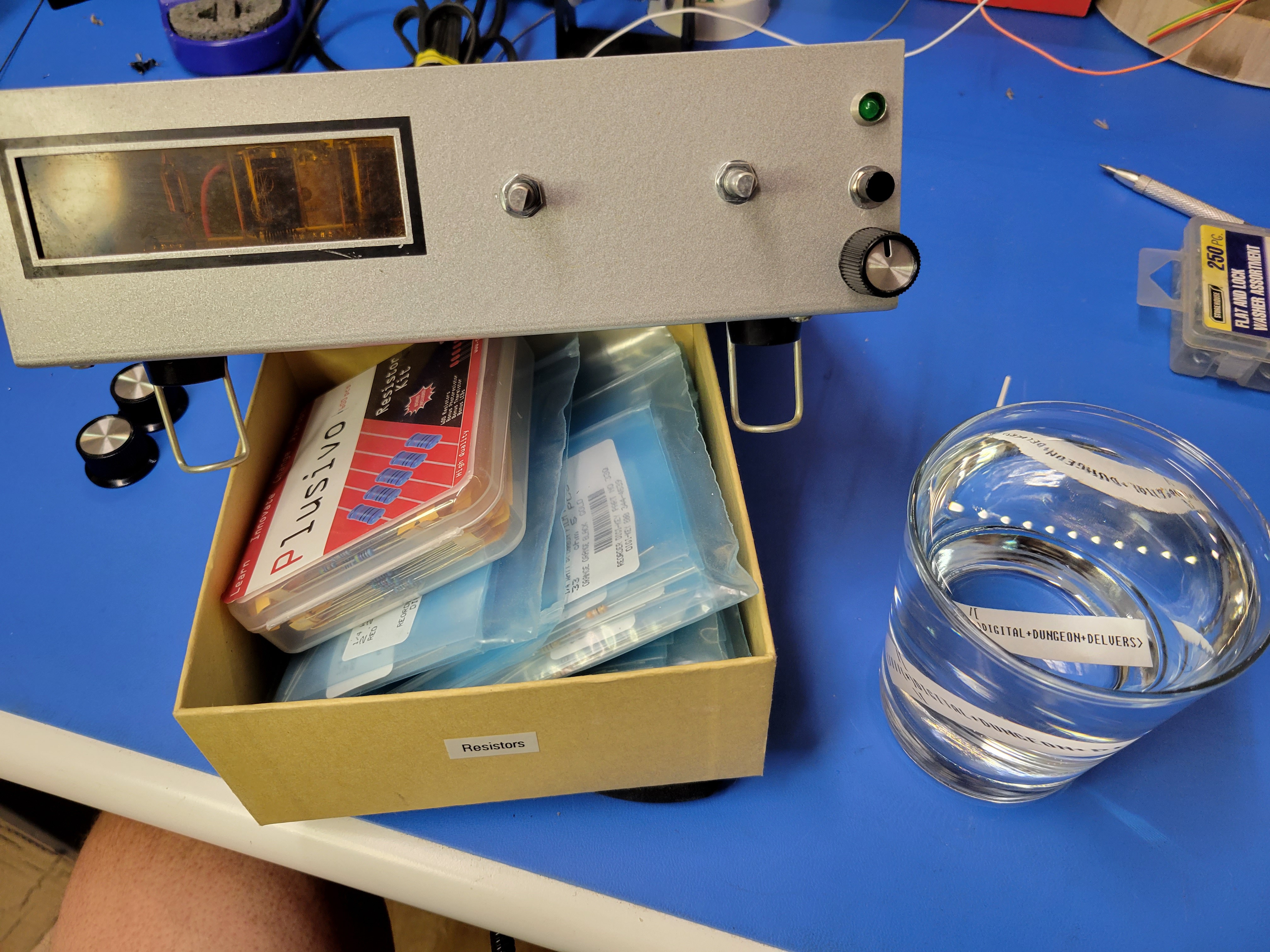
Print out the graphics and cut them out. Then, soak them one at a time in warm water for exactly 30 seconds. I say that because if you soak them any longer the decal will come off the paper backing before you pull it from the water. Pull the paper with the decal from the water and slide the decal off the paper (or the paper out from under the decal) as you hold it against the face plate. Once the backing paper is out, you can very gently slide the graphic around. Try to minimize this. It's possible to fold over or rip the graphic if you work it too much. Also, I have found it easier to put the decals on with the knobs off. However, you'll want to put the knobs on temporarily to determine where to place the graphics. If you didn't place water slide decals on your plastic models (cars and planes), I suggest looking up some YouTube videos demonstrating how to best place water slide decals.
Let the decals dry overnight.
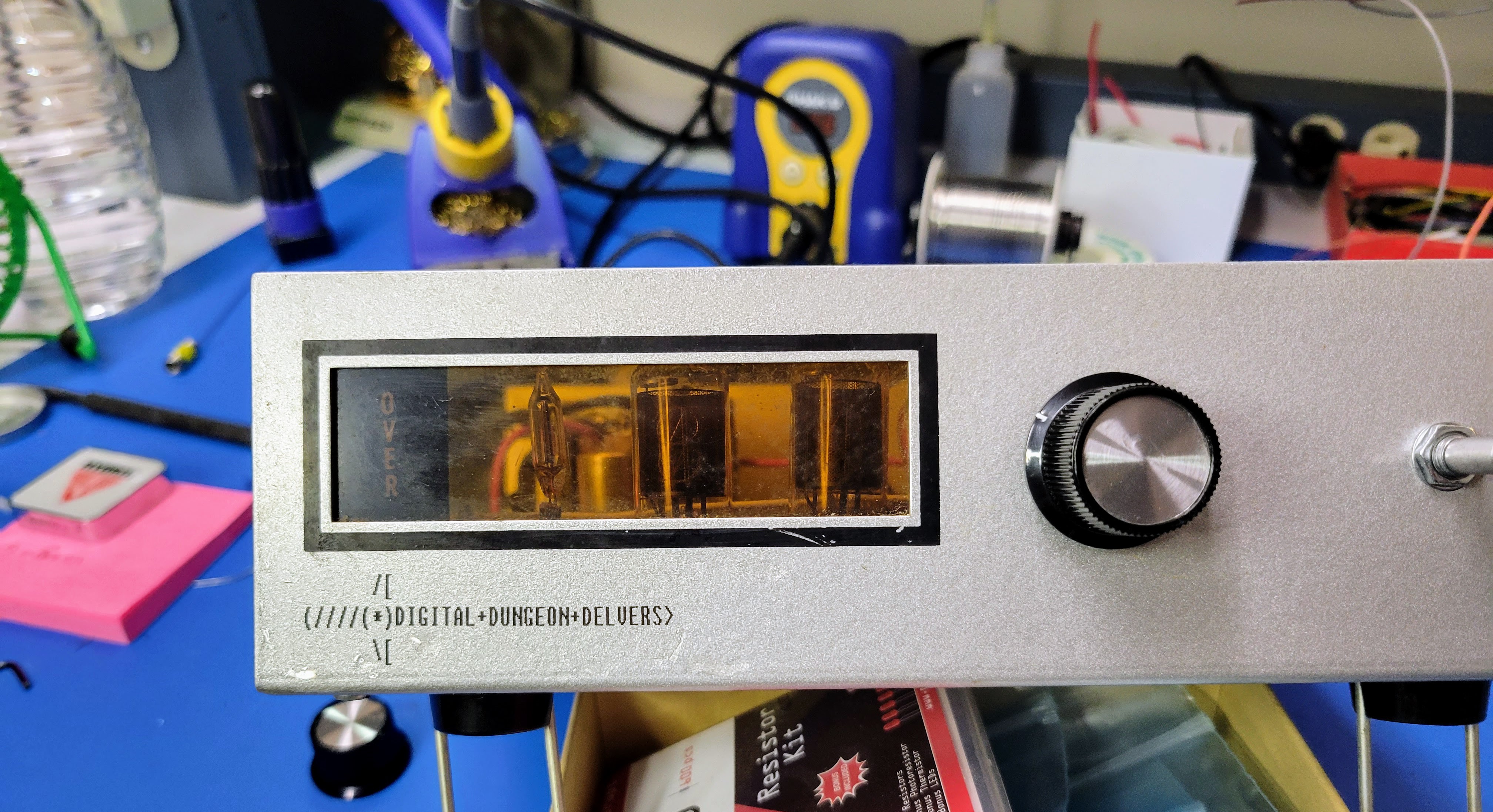
At this point, your device should be looking something like this. It's now ready for the MCU. We'll program that and insert it in the next blog.
Discussions
Become a Hackaday.io Member
Create an account to leave a comment. Already have an account? Log In.