 John Anderson
Now that the controller board is built and installed, the next step is to load the application into the MCU flash, install the IC's, and test the device.
Start by downloading the BH_DiceTower.zip file from the project page here. Unzip that into a location in your local storage. You will load the application from there.
If you don't already have it, you will have to download and install the Microchip Studio software next.
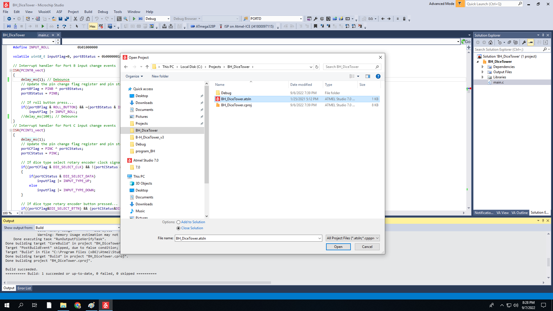
Then, start the Microchip Studio application and load the BH_DiceTower.atsin project.
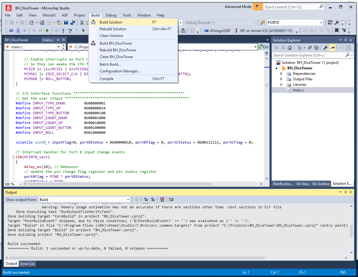
The project comes with the solution already built with .s19 and .hex files that can be loaded to the MCU flash. However if you make changes to the source or simply want to rebuild it, select Build | Buils Solution from the application menu.
With the source built, the next step is to setup the MCU and program it's flash. To do so, you need a programmer and a board with a 28 pin socket for a ATmega 329P MCU and ISP programming port. I use an Atmel-ICE for my programmer. There are cheaper options, but I can't say enough good things about the Atmel-ICE. It provides seamless debugging for AVR and SAM MCUs using multiple interfaces like ISP and UDPI. If you want use something else, I'll leave it to you to research how to make that work. It's also an option to take the .hex or .s19 files from the project and program the MCU using a programmer with the Arduino IDE. However, I am not familiar with the Arduino IDE. So again, that's left as an exercise for the user.
For the board with the ISP port, I used to add an ISP port directly to the controller board. This is still an option and a little web research will turn up how to wire that up. You can see in one of my previous project blogs where I did just that on a different configuration of the controller baord.
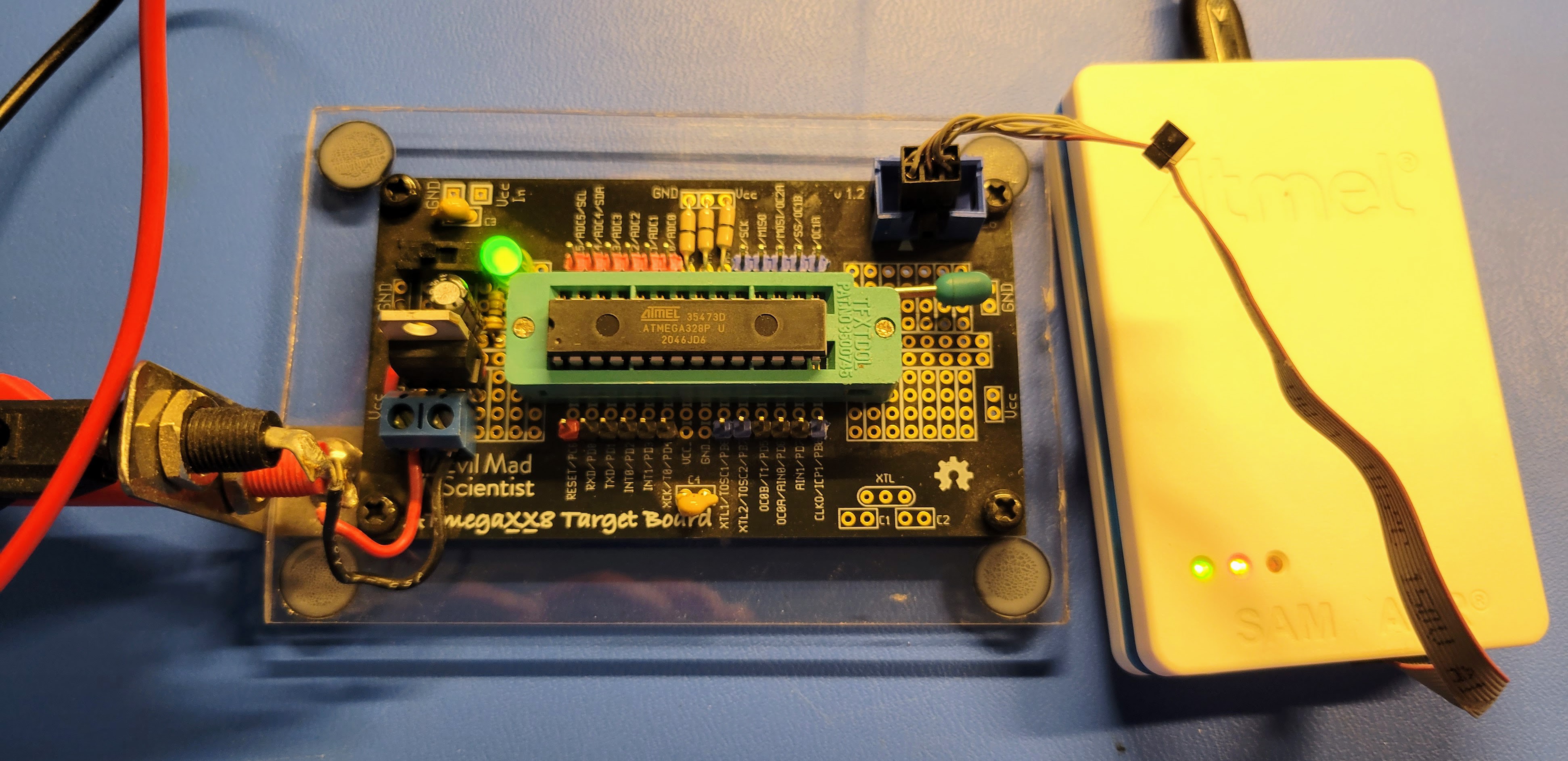
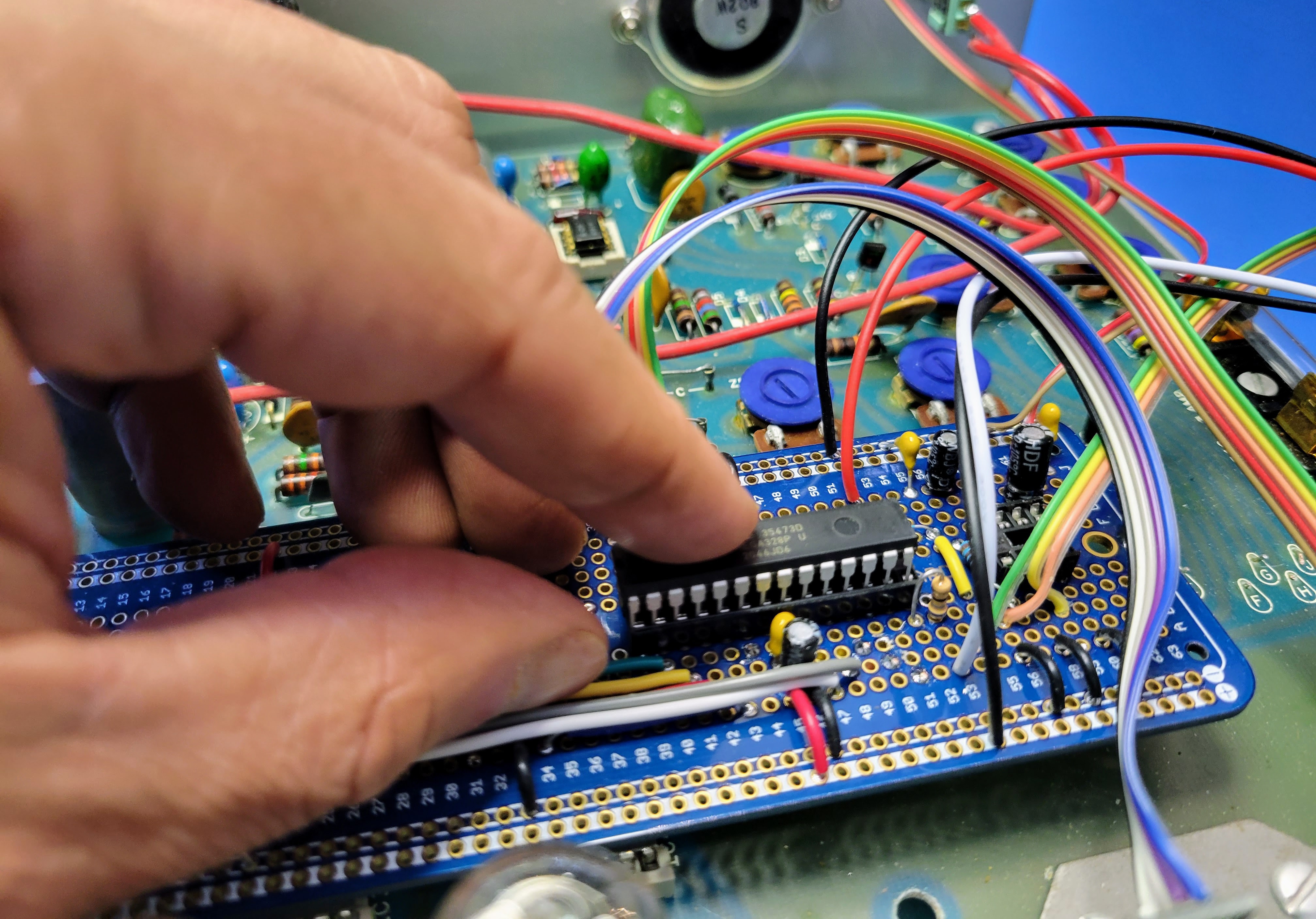
I now use a Evil Mad Scientist ATmegaXX8 Mini Dev Kit (https://shop.evilmadscientist.com/tinykitlist/230). They are cheap and very easy to build. I upgraded my board with a 28 pin ZIF socket, 7805 5v voltage regulator, and mounted it to plexi-glass base with banana connectors for power connect. With this setup, I can use a 12v bench power supply or wall wart and program 328's for use on various boards.
Here's a pic of my programming setup.
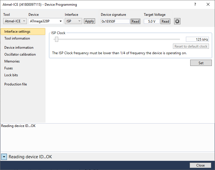
To program the MCU, select Tools | Device Programming from the Microchip Studio application menu.
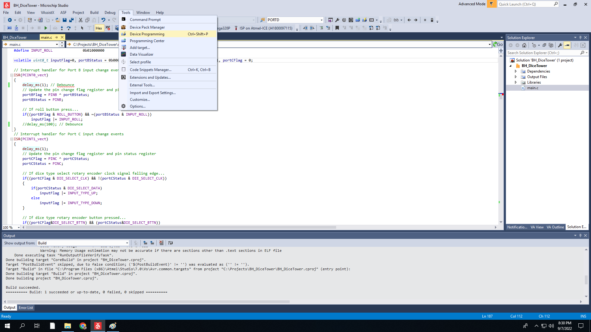
A pop up dialog will appear. In this dialog, select the programmer (Tool), MCU (Device), and programming port (Interface). In this case, it's Atmel-ICE, ATmega328P, and ISP in that order. Then click the Apply button. This will connect to the programming device. Clicking either of the Read buttons will connect the programmer to the MCU using the interface. This will confirm that the MCU can be programmed.
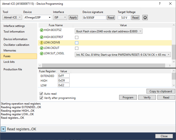
Next, select Fuses in the left pane. In the right pane, scroll down and deselect the LOW.CKDIV8 fuse. Then, click on the Program button below that. The pop up window will report that "Verify registers ... OK" in the bottom status line. This turned off the divide by 8 on the internal clock. If you don't do this, the audio will be garbled. The software's PWM setup assumes this flag is cleared.
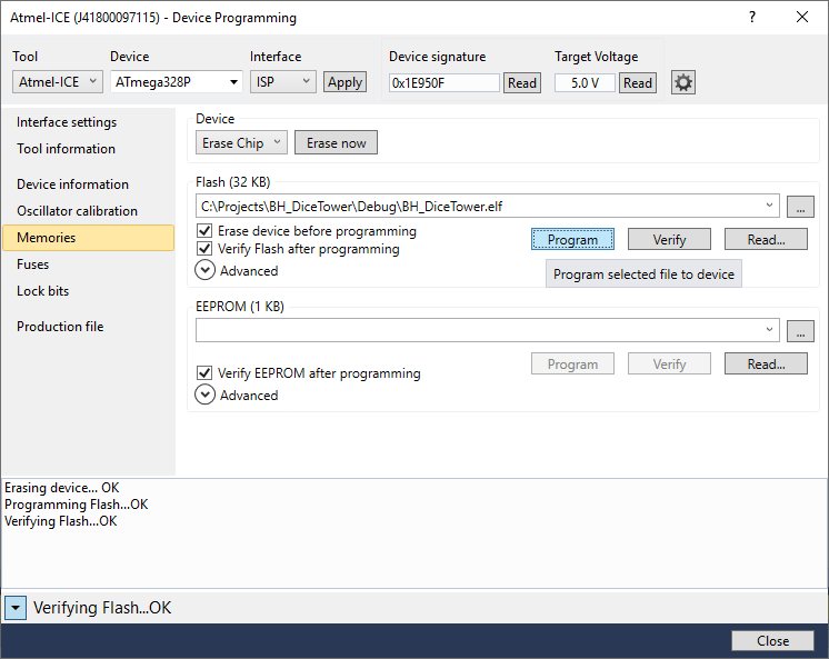
Next, select Memories in the left pane. In the right pane, click the Program button. With the default Interface settings, this step will take about 15 to 20 seconds. When it completes successfully, the status line at the bottom of the pop up will report "Verifying Flask ... OK". At this point, the MCU is programmed. So, turn off power on the board and remove the MCU.
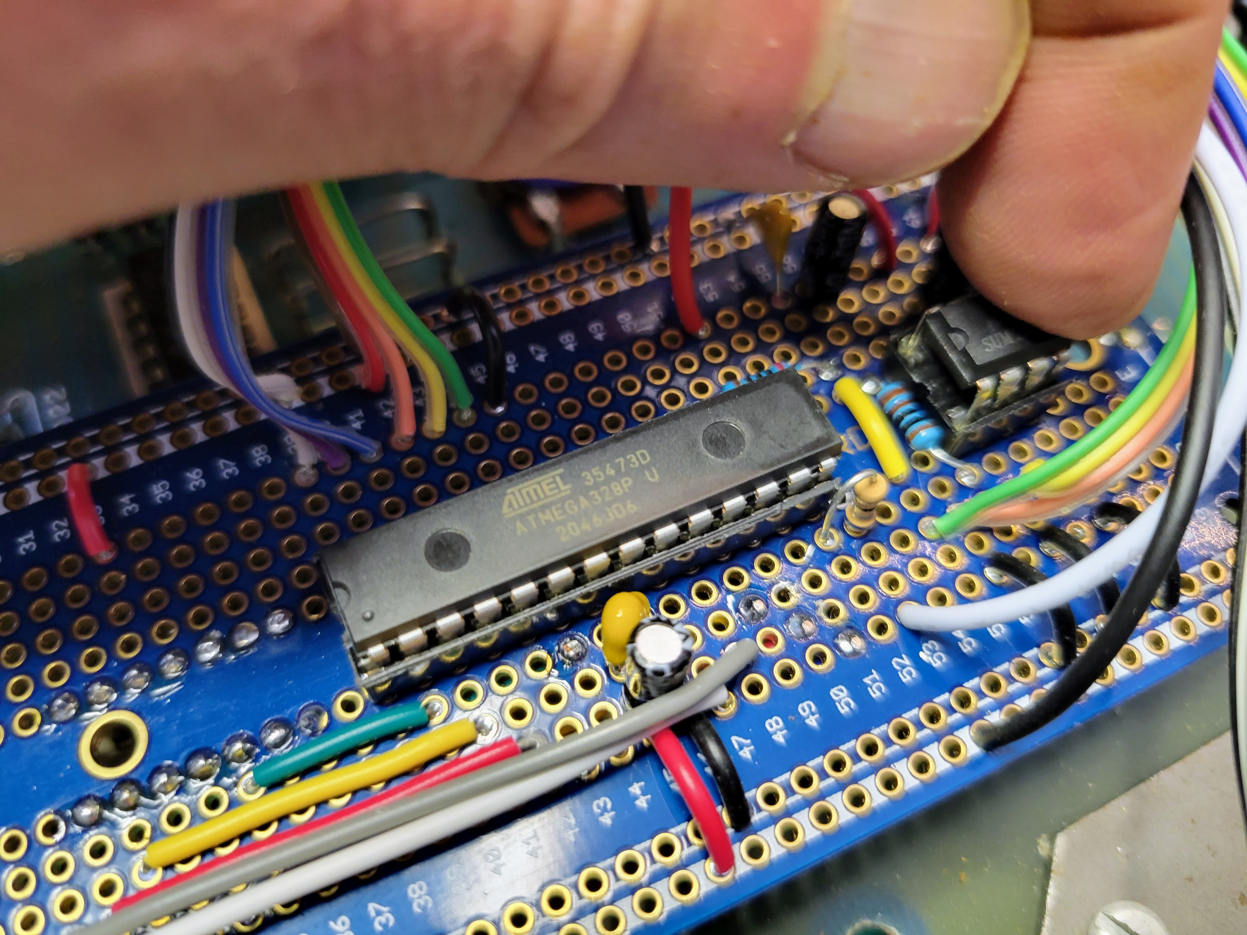
Next insert the MCU in the 28 pin socket on the controller board, paying attention to where pin 1 is correctly located. Note: this end of the controller board is not supported and simply pressing the IC into the socket will dislodge the controller board from the PCB sockets. So, support the end of the controller board with your other hand/fingers as you locate and press the IC into the socket. The same goes for the audio amp IC.
It's an option to install stand-off on this end of the controller board and mount them to the PC. These would need to be very small standoffs.
Then insert the 8 pin LM386-1 audio amp IC into the 8 pin socket. Again, pay attention to the correct location of pin 1.
At this point, the controller board is complete. Replace the case top cover and thread the 4 screws in place to hold the cover. Then, turn on the device and see/hear the glory of the Digital Dice Tower.
Caution: If it doesn't work as expected, care must be used while debugging the circuit with the power on. Inside the case there is 120 volt AC and 170 volt DC. These can and will cause injury if you short them across your fingers, hand, body, etc. The controller board itself is relatively safe to probe and touch while operating. It's all 5 volt logic and analog signals.
Note #1: I purchased a set of inexpensive LM386 audio ICs from a source on Amazon. Of the 10 ICs I purchased, only 5 of them were functional. It took some experimentation to figure out which worked. I highly suggest sourcing those from a reliable source.
Note #2: I purchased the rotary encoders from a source on Amazon as well. I have had some bad luck with those as well. Of the 4 batched of 10 I have purchased. One complete batch was non-functional. In the current batch of 10 that I am using for boards, 1 of the 10 was non-functional.
Note #3: I missed wired the result LED originally. You can see it in the picture above. The ground wire was connected to the 5v bus. This did not cause any damage to the controller board or the LED. But, I did have to re-land it on the ground bus to get the result LED to work correctly.
Discussions
Become a Hackaday.io Member
Create an account to leave a comment. Already have an account? Log In.