 Michael Wessel
Introduction
Talker/80 offers:
-
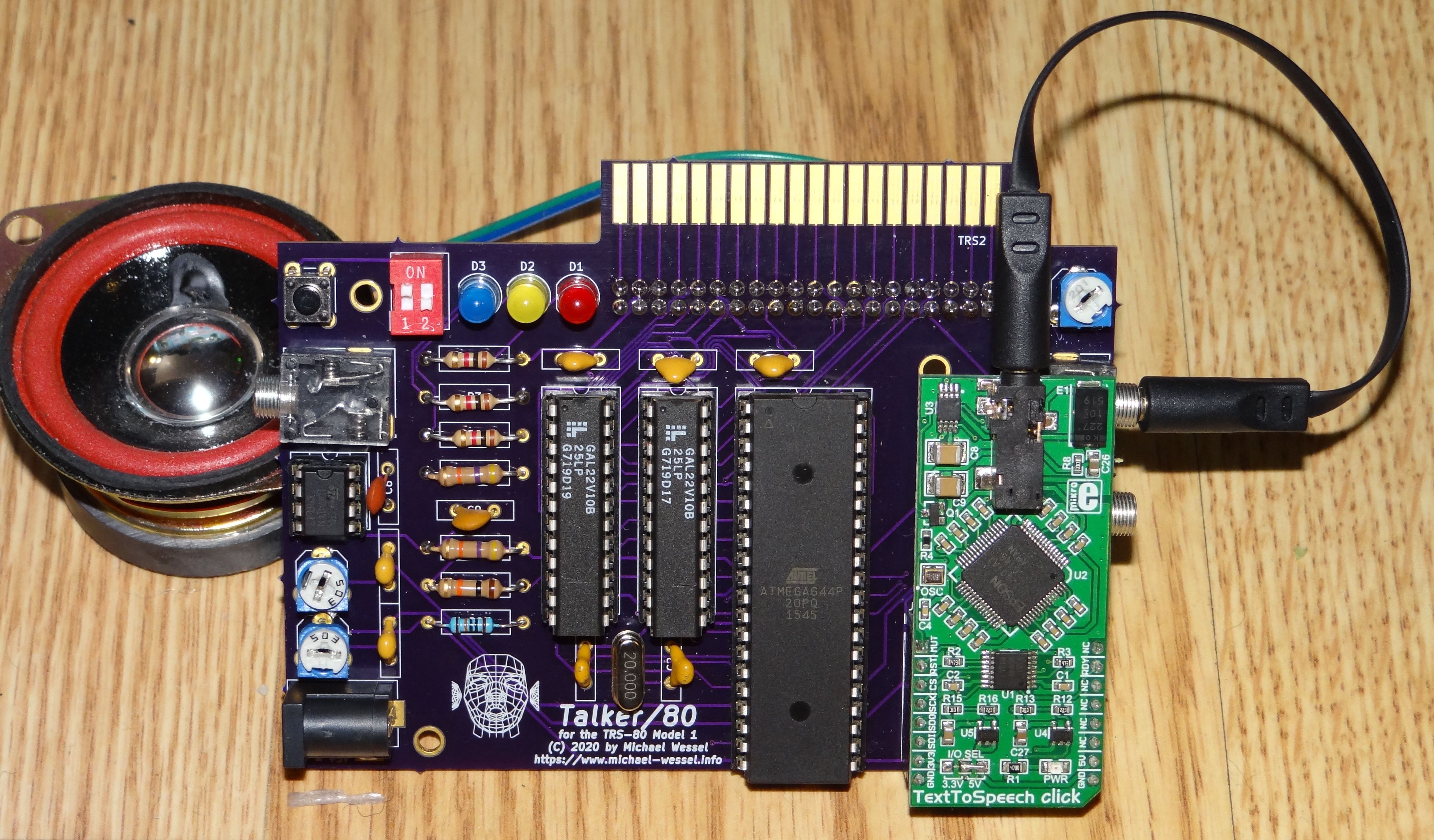
DECtalk-Based Text-to-Speech (TTS) Synthesis: the Epson S1V30120 TTS chip on the utilized mikroBUS "TextToSpeech Click!" daughterboard from MikroElektronika implements DECtalk v5 - a natural sounding speech synthesizer for English and Spanish, with different voices. DECtalk can even sing. The DECtalk mode is very powerful and versatile, but the DECtalk control language can be difficult to program. Hence, a simplified control language for the S1V30120 is offered as well, the so-called Epson mode. DECtalk mode is used to implement emulations of two classic TRS-80 Voice Synthesizers: the official TRS Voice Synthesizer from Tandy Radio Shack, and the VS-100 Voice Synthesizer from Alpha Products. Both use the Votrax SC-01 as their underlying speech chip. Talker/80 emulates the SC-01 by means of DECtalk here. The DECtalk and Epson modes produce superior speech quality, and text-to-speech is performed by Talker/80 itself, i.e., no breaking down into phonemes is required. Text to be spoken can be sent directly to IO port 11, and the status of the speech synthesizer is checked by reading from port 11.
-
TRS Voice Synthesizer Emulation: the emulation in terms of DECtalk as just described is good enough to produce understandable speech, but it sounds different than the Votrax SC-01-A chip. Original software such as the TRS Voice Synthesizer BASIC Demo Program, and "Talking Eliza" work out of the box, but note that the emulation is only 80% faithful or so.

Votrax SC-01-A Speech Chip -
VS-100 Voice Synthesizer from Alpha Products Emulation: another classic TRS-80 voice synthesizer. Also used the Votrax SC-01, but was / is not compatible with the TRS Voice Synthesizer. Talker/80 uses the same method of emulation (mapping to DECtalk phonemes). Same comments wrt. buffering etc. apply. Original software works without patches (e.g., VS48 and VS-100DEMO.BAS etc.). In addition, pitch control is currently no supported, so the speech will be monotonous.
-
Cassette Sound Input Port and Audio Mixer: Talker/80 is equipped with two input stero mini jacks - one for the output from the MikroElektronika speech daughterboard, and one can be connected to the TRS 80 Cassette Output Port for sound (or any other source, really). The signals are being mixed. Two input pots on the right and corresponding trimmers on the left side are used to determine the two signal levels for the mix. The mixed LM741 output signal is available at the output mini jack on the left side.
-
Optional Amplifier and Loudspeaker: In addition, a little "off the shelf" D-class audio amplifier can be fitted on the PCB. The two input signals (after the pots / trimmers) is being amplified. The output is available to the loudspeaker pin header at the back of the PCB. The output volume is controlled by the trimmer / pot at the top right.
-
Expansion Port Pass Through Connector: The Model 1 Talker/80 connects directly to the Model 1 expansion port, or, if an Expansion Interface (EI) is available, to the Expansion Port passthrough of the EI (this is the port in the left front corner on the left side). The Talker/80 expansion port edge connector is at the back of the PCB. You can either connect the EI directly to the Model 1, or to Talker/80's edge connector. Talker/80 is fully compatible with the EI, Floppy Disks, FreHD, etc.
-
DIP Switch for Initial Mode Selection: for selecting the intial startup mode of Talker/80. The mode can be changed via software as well (by sending a so-called "control byte").
-
RESET button: for reinitializing / "rebooting" Talker/80. In combination with the DIP switch, the mode can be changed easily without having to use software to send control bytes.
-
Three LEDs: These LEDs are used for mode indication, to signal data being received, to indicate when Talker/80 is speaking, and when a single phoneme is being uttered. LEDs will also indicate errors.

A main difference between the DECtalk-based emulation and the original synthesizers is that it is not possible to utter phonemes "in realtime", as DECtalk requires phoneme buffering and processing before they can be spoken, unlike the SC-01-A, which is able to utter a phoneme immediatly (they can, for example, be used as "realtime sound effects"). This is exploited, for example, in the TRS Voice Synthesizer BASIC Demo Program, which spells out individual phonemes in real time ("the phonemes in the word zero are: z e r o" etc.) Due to the buffering requirement for DECtalk, this is challenging to get right. Please check out my demo videos below to see if you can live with the result.
TRS-80 Model 1 Connection & Startup Sequence


Talker/80 gets its power from a standard, voltage stabilized 5V power supply ("Wall Wart") with positive center polarity, 5.5 mm x 2.5mm. It connects to the Talker/80 Barrel Jack.
It is very important that your equipment is powered on in the right order of sequence:
- Make sure everything is powered off.
- Make sure everything is connected correctly (Talker/80 to the Model 1, Expansion Interface (EI) to Talker/80 if present - note that it does not require the Expansion Interface). Alternatively, you can also keep the EI directly connected to the Model 1, and connect Talker/80 to the EI Expansion Port passthrough port (the edge in the left front corner on the left side of the EI).
- Supply power to Talker/80 by plugging in the PSU. You should hear "Talker/80 initialized" and an announcement of the current mode, which depends on the settings of the DIP switches.
- Power on your Floppy Drives, Printer, etc.
- Power on the Expansion Interface.
- Power on the Model 1.
Hardware Description
Talker/80 uses an ATmega 644-20 (U4) clocked at 16 MHz as its microcontroller. The firmware has ~ 45 KBs. The firmware was programmed in C, using the WinAVR / GCC toolchain. At startup, the ATmega loads the Epson firmware image (implementing DECtalk) over SPI into the speech daughterboard. At runtime, SPI is used as well. External interupts are being used to register read and write requests. The address decoding is done by a GAL20V10 (U1), and another GAL20V10 (U2) is acting as a tristate databus latch and also provides status input (bits 6 and 7) to the TRS-80 in all modes other than the TRS Voice Synthesizer emulation mode. U5 is the op-amp.
The current mode of Talker/80 is being signaled to the address decoder GAL U2, using 2 bits for the 4 different modes. Depending on the mode, the GAL U2 either decodes IO requests (using IN and OUT signals), or video RAM addresses (and signals RD and WR) to implement "video RAM snooping" (a form of memory-based IO) as required for the TRS Voice Synthesizer. The details can be found in the GAL code.
Applications can read from IO port 11 to find out if Talker/80 is actively speaking. Note that input to Talker/80 is always buffered, so realtime control of the speaking process (e.g., "voice synthesizer sound effects") is not achievable.
Address Decoding in the Epson and DECtalk Modes
Talker/80 listens to port 11. For the text content, 7 bit ASCII is being used. The text-to-speech conversion is performed internally, so no phoneme encoding on the TRS-80 side is required. Input from IO port 11 is being buffered. The buffer has a size of 256 bytes. A return (CR / ASCII code 13) initiates the text to speech process, and Talker/80 starts to speak (if the buffer had content). While it speaks, bits 6 and 7 of port 11 will be low - use inp(11) AND 192 to check for bits 6 and 7 being set in BASIC.
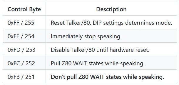
ASCII characters being sent to port 11 which have its 8th bit (Bit 7) set (i.e., bytes > 127) are being interpreted as control bytes. Control bytes are used to control the Talker/80, i.e., to change its current mode, to change parameters of the speech (voice, speak rate, volume), etc. The list of control bytes is given below. For example, to reset Talker/80, send 255 to IO port 11 (use out 11,255 in BASIC).
Speech can be blocking or non-blocking. In the blocking mode, the Z80 CPU is suspended by pulling its WAIT input low.
Address Decoding in the VS-100 Mode
The primary IO port the VS-100 is also port 11. And like in the Epson and DECtalk modes, one can read the status from port 11. Bits 6 and 7 (the byte starts with Bit 0) indicate if it is busy speaking.
Lazy / partial address decoding is being used, just like in the original VS-100. Partial address decoding was used to reduce the address decoder complexity and hence chip count and costs. According to information from members of the Vintage Computer Forum, the following IO ports can also be used to address the VS-100 ("it responds if bits 7, 5, 4 and 2 are 0, don't care for others"):
- 0, 1, 2, 3
- 8, 9, 10, 11
- 64, 65, 66, 67
- 72, 73, 74, 75
Unlike the DECtalk and EPSON modes, text to speech / encoding of text into phonemes has to be performed on the TRS-80 side. SC-01 phonemes are being sent, not ASCII text characters.
These are the SC-01 phonemes; the VS-100 phonemes are identical:

Note that, in order to do the text-to-speech / phoneme mapping, the VS-100 software driver can be used (the programs VS48 and VS32). These drivers allow text-to-speech from BASIC then, so the driver performs the text to phoneme mapping.
Talker/80 does not implement the pitch control feature of the SC-01. The VS-100 uses the last two bits (Bits 6 and 7) of the phoneme bytes to encode / provide pitch control; i.e., each phoneme has in principle 4 different "pronunciations" or "pitches". These two pitch bits on phonemes are currently being ignored by Talker/80 and hence not supported. To prevent interference with existing VS-100 software, the control bytes understood by Talker/80 in the DECtalk and EPSON modes, are NOT supported in the VS-100 mode.
Since control bytes are not accepted in this mode, all changes to the default settings need to be made BEFORE entering the VS-100 mode. For example, if a different voice, speech rate or volume is required in the VS-100 mode, then make these changes to the setting from the EPSON or DECtalk mode first, and then enter the VS-100 mode from using the corresponding control byte &EB. The changed voice synthesizer settings will then carry over to the VS-100 mode. The mode can only be exited by using the RESET button.
Here is a picture of the original VS-100 Voice Synthesizer:

Address Decoding in the TRS Voice Synthesizer Mode
The TRS Voice Synthesizer uses memory-based IO.
It snoops writes to the video RAM in the address range $3FE0 .. $3FFF. Only the temporal order of writes matters, not the actual address from that range. Hence, in this mode, any write (WR signal) in that address range will put a byte in the Talker/80 speech buffer.
A special protocol is being used. Even though the TRS Voice Synthesizer employs the same speech chip as the VS-100, the SC-01, it is not using the SC-01 phonemes directly. Rather, Tandy Radio Shack invented a "printed" phoneme character set for some of the SC-01 phonemes. A special character, the "?" opens and closes the "window" to the Voice Synthesizer.
The TRS Voice Synthesizer's printed ASCII phonemes for some of the SC-01 phonemes are the following:

Note that, like in the VS-100, control bytes are not accepted in this mode, as normal "to screen" printing might otherwise trigger them. If a different voice setting is required in the TRS Voice Synthesizer mode (e.g., a different voice, speech rate or volume), then the setting must be changed from the EPSON or DECtalk mode first, and then the TRS Voice Synthesizer mode be entered using the control bytes &ED or &EC. The changed voice synthesizer settings will carry over to the new mode, and be active from now on. The TRS Voice Synthesizer mode can only be exited via the RESET button (since no control bytes are accepted).
Here is a picture of the original TRS Voice Synthesizer:

Phoneme Tables and Phoneme Mappings
The VS-100 and TRS Voice Synthesizer Emulations work by mapping SC-01 phonemes to DECtalk "close enough equivalents". This produces understandable speech, but the resulting speech sounds different from the original SC-01.
The Talker/80 Printed Circuit Board (PCB)
Talker/80 was made with KiCad EDA v4.0.7, and "freeRouting.jar" did the routing.

The DIP switches are used for initial boot / startup mode selection (note that the mode can be changed later by sending a control byte); for switch 1, 2 from left to right:
- 0n 0n: EPSON Mode.
- 0n Off: TRS Voice Synthesizer Mode.
- Off On: VS-100 Voice Synthesizer Mode.
- Off Off: DECtalk Mode.
The LEDs have the following meaning - during startup and after mode selection, they briefly indicate the selected mode. The blink in case of errors. In normal operation, they have the following meaning:
- D1: Incoming data.
- D2: On if a single phoneme is being uttered, and when the "stop speech" command is being processed.
- D3: Actively speaking.
Schematics
Model 1 Version
 Click here for a PDF version of the schematics of the Model 1 version.
PCB Gerbers


Gerbers of the Model 1 version can be found here.
A version is also hosted on OshPark for immediate ordering of PCBs. And another one on Seeed.
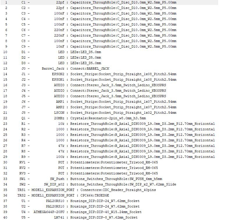
Bill of Material
Please note that, different from the BOM given below, the clock frequency is now 16 Mhz instead of 20 MHz. So you will need a 16 MHz crystal instead of the listed 20 MHz crystal. The Makefile allows specification of the clock frequency. The default firmware supplied here, talker80-firmware.hex, runs at 16 Mhz by now. If you have a 20 MHz crystal at hand, that should also work, but you will need to change the Makefile accordingly and recompile the firmware with WinAVR
Tips:
I recommend to use standard stackable Arduino Headers for J1 and J2 (instead of soldering the daughter board in permanently). For the amplifier board, J6 and J7 are simple pin headers that make the connection to the amplifier board:

The form factors in the above BOM are for illustration only. Instead of ceramic disc capacitors, I have used ceramic multilayer capacitors mostly. I recommend using DIP sockets for all chips. The values for the pots / trimmers are 503, 503, and 201 (speaker volume).
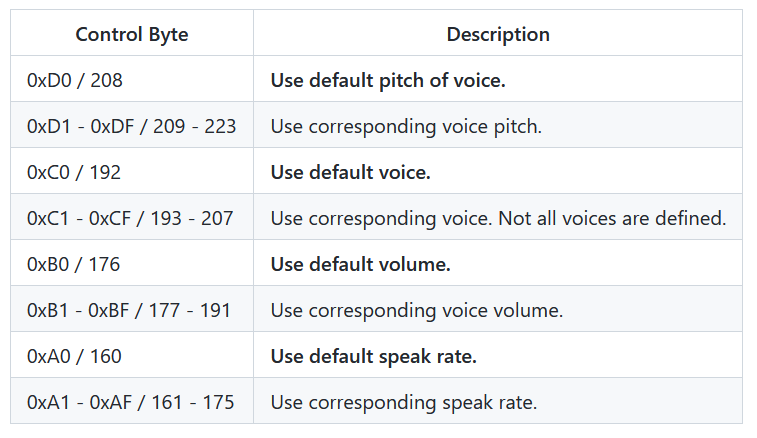
Talker/80 Control Bytes
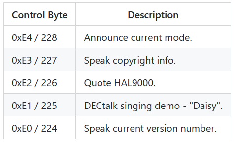
These are the control bytes that are ONLY understood in the EPSON and DECtalk modes, in order to prevent interference with screen printing (TRS Voice Synth) and pitch control bit (VS-100). However, you can change the firmware if desired to change this.
Default settings are shown in bold:

Talker/80 Programming
Have a look at the BASIC programs provided on the disk images (see below).
The Talker/80 Firmware
- GAL22V10 JEDEC Address Decoder JED File
- GAL22V10 JEDEC Address Decoder WinCupl Source
- GAL22V10 JEDEC Databus Buffer JED File
- GAL22V10 JEDEC Databus Buffer WinCupl Source
- ATmega 644 Firmware HEX File
- ATmega 644 Firmware C Source
Model 1 Breadboard Prototype

First Model 1 PCB Version


Final Model 1 PCB Version


Some YouTube Videos of Talker/80 in Action
- First Breadboard Prototype
- First PCB Version
- Towards the TRS Voice Synthesizer Emulation
- VS-100 Emulation and More Complete Demo of Features
- "Talking Eliza" with Talker/80
- Demonstration of Talker/80 BASIC DEMO Programs
Maker Support
The Gerbers and Firmware and all specs (BOM, ...) are all open source and in principle you can build one yourself. However, if you require certain parts or a pre-programmed GALs, the ATmega, or even a fully assembled Talker/80, please contact me.
Acknowledgements
Thanks to Teodor Costachioiuo for the Talking Clock Tutorial with the Mikroelektronika Text to Speech Clock Board; I have rewritten this (Arduino) code and ported it to WinAVR.
Elliot Wiliams for his book "Make: AVR Programming" and corresponding sources /AVR Programming Libraries..
Special thanks to member of the "Vintage Computer Forum" (especially to "Joe Zwerko"!) for providing crucial info, such as the phoneme tables for the Votrax SC-01 and the TRS Voice Synthesizer.
Thanks to the TRS-80 "TrashTalkers" for inviting me to give a presentation about Talker/80:
https://www.trs80trashtalk.com/2020/06/episode-36.html
Also thanks to "The Homecomputerguy" who took his Talker/80 to the "Classic Computing 2021" fair in Vöhringen! Thanks for the great video and for demoing Talker/80!