 Guillermo Perez Guillen
Summary
Below, I show you the project wrap-up and lessons learned of this cost-effective solution:
Getting Started
Here I describe the technical characteristics of the Arduino MKR WAN 1300 board, the installation of the board in the Arduino IDE application, as well as the firmware update. Finally we test the Blink.ino demo code to check if the boards are working fine.
Communication Between Two MKR WAN 1300
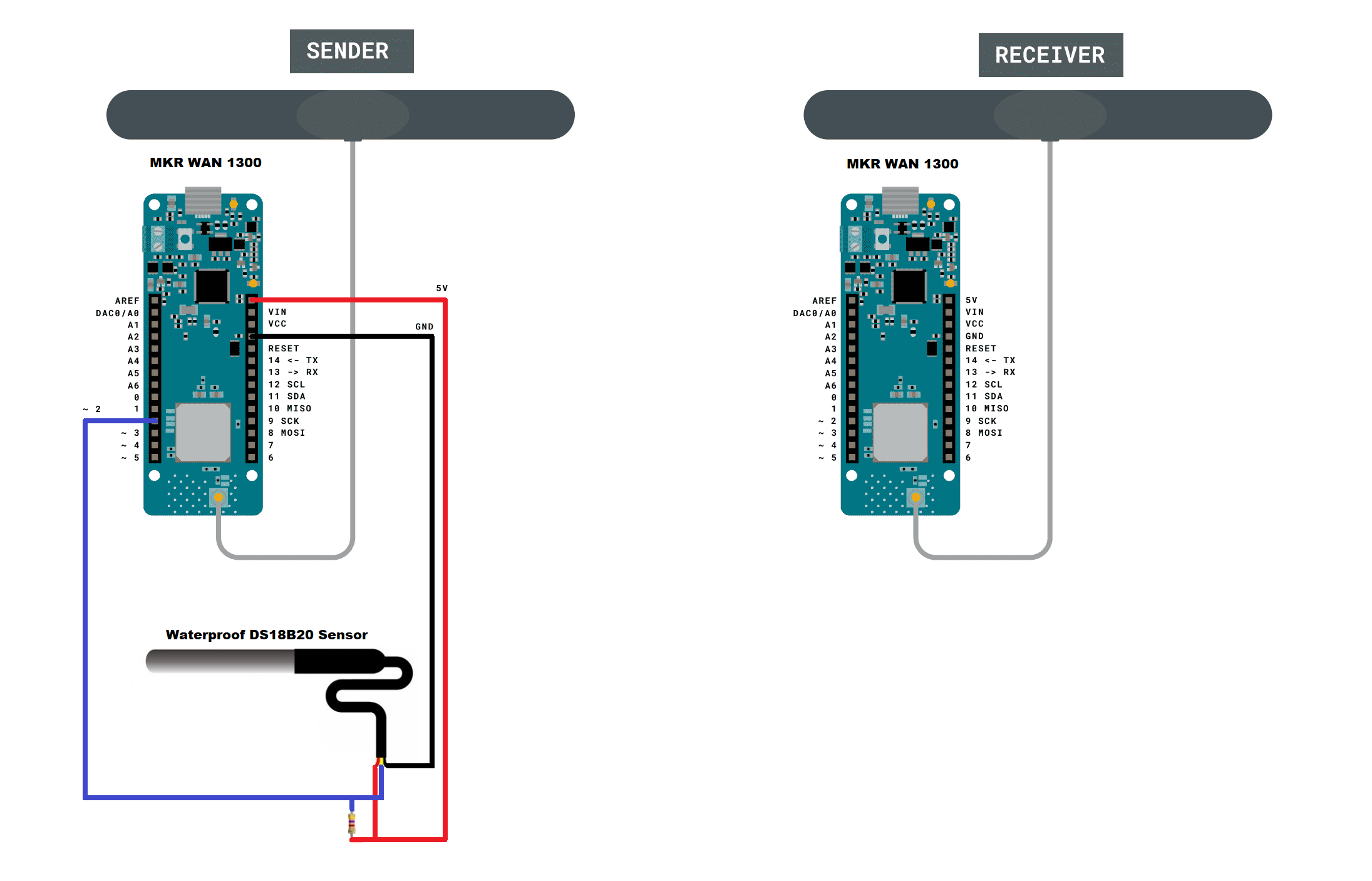
Here we start with the most basic, which is the point-to-point communication between two Arduino MKR boards. The transmitter sends data from the Waterproof DS18B20 sensor, and every time the receiver receives data, an LED on the board flashes and the serial port shows us the temperature of the sensor.
LoRaWAN System Range Testing
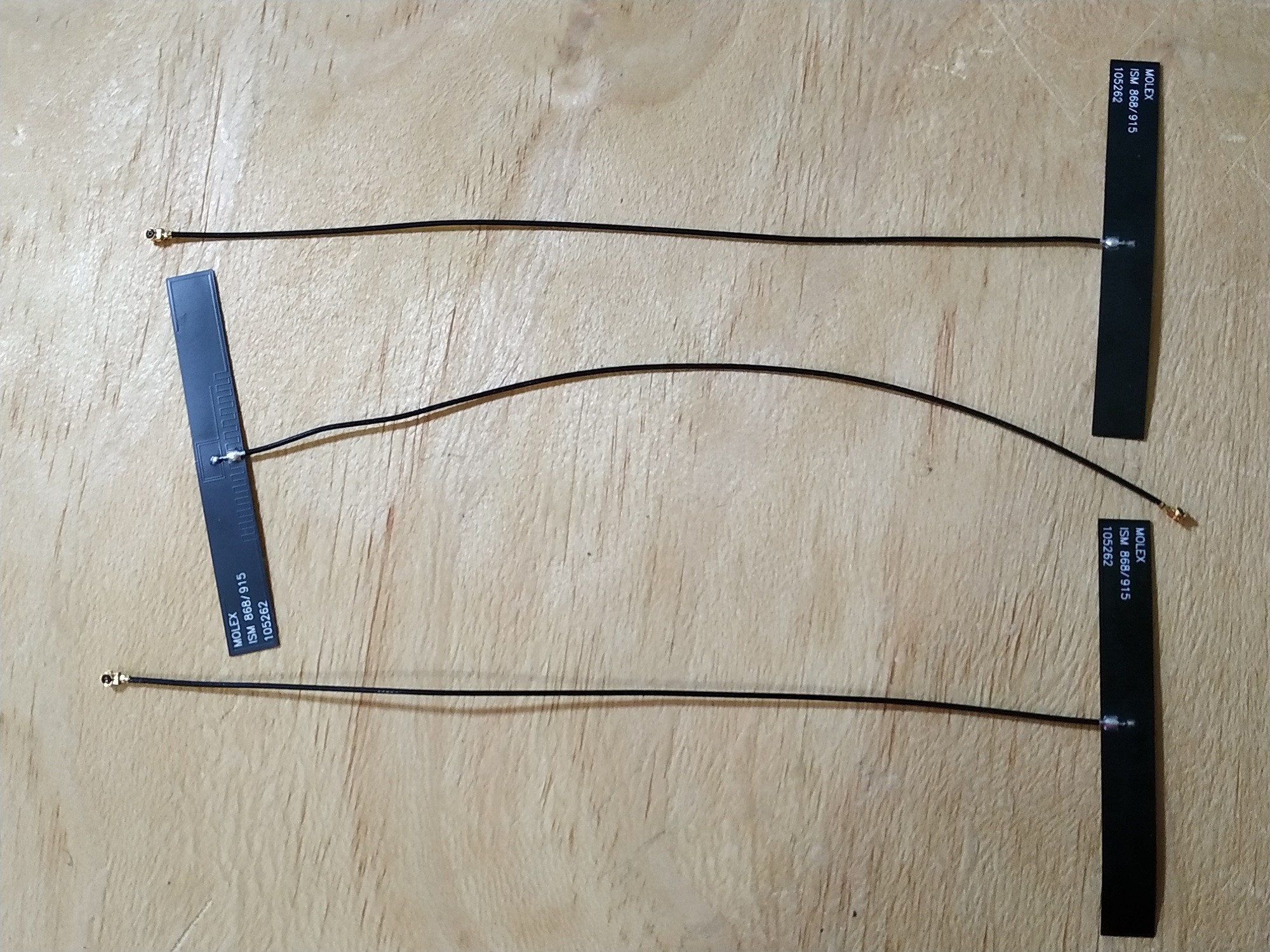
The next test is to check the link quality between the transmitter and receiver. So I make a comparison between different RF antennas, and finally the ones that showed the best performance are the manufacturer's dipole antennas. It is important to take care of this detail to avoid bad RF communication or corrupt messages.
Assembling the Transmitter
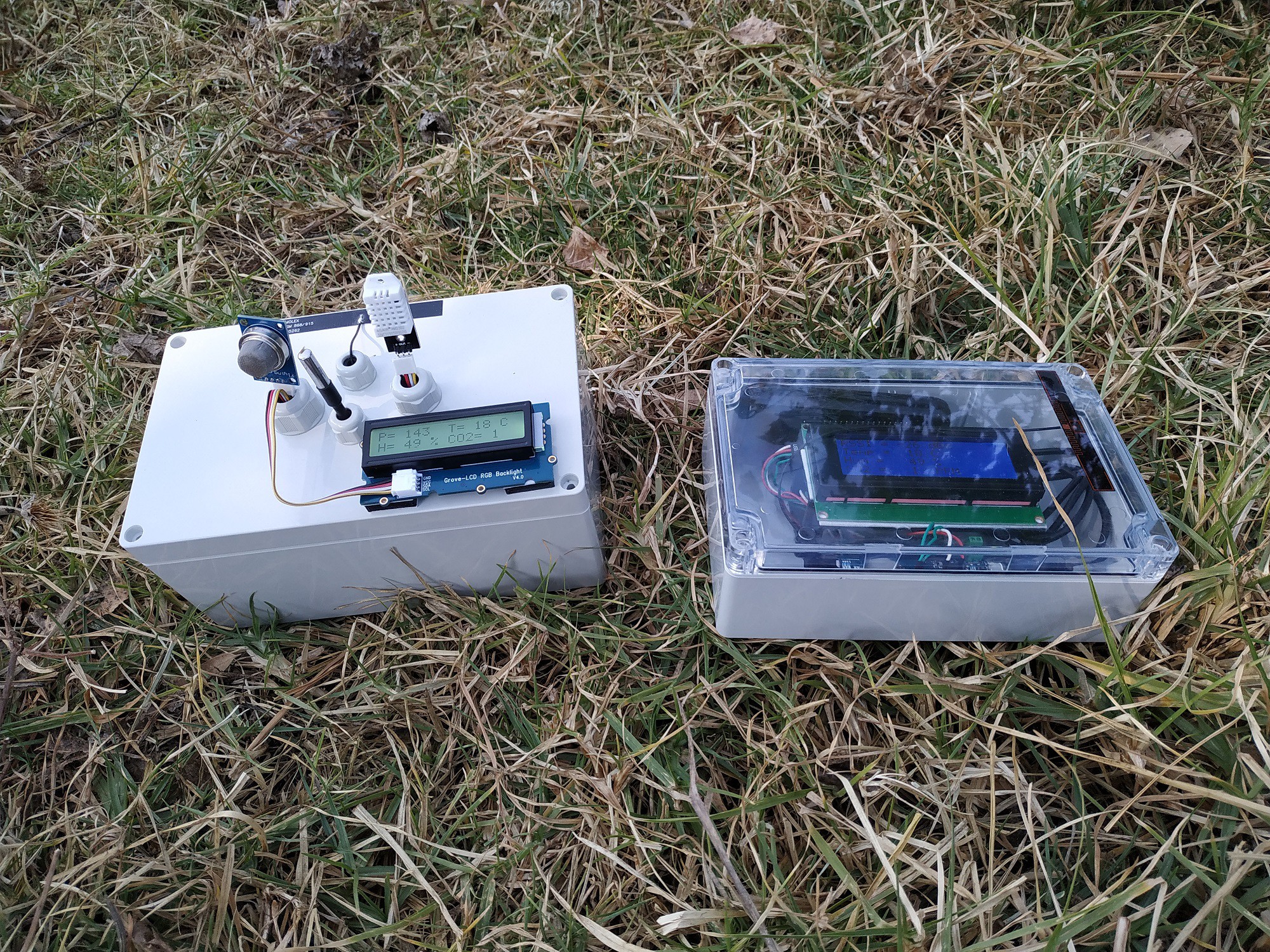
It’s time to assemble the transmitter module and add a LCD display to it. Here I have used the case and the Grove-LCD RGB Backlight, and the assembly steps can be found in this tutorial.
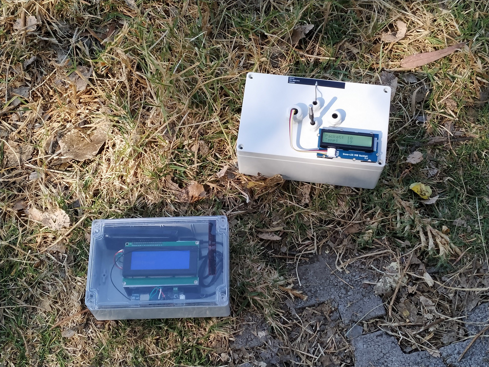
Assembling the Receiver, and LoRaWAN´s Field Test with a DS18B20 Sensor
I have also added the steps to assemble the receiver module with a 20x4 LCD display in this section as shown in the image below. Once we have assembled the LoRaWAN transmitter and receiver modules, its time to test them in the field. As a preliminary test, I did hardware and software verification before going out to the field.
Adding Multiple Sensors: DS18B20, DHT22 and MQ-135
We still continue with the point-to-point links between two Arduino MKR WAN boards, but this time we will do it with multiple sensors. I have added the DHT22 humidity sensors and the MQ-135 air quality sensor to the transmitter module. Here I have used a method to join the data using the comma character.
Modifying Receiver Code for Multiple Sensors, and LoRaWAN´s Field Test with Multiple Sensors
Here I show you how to modify the code of the receiving module to separate the data from multiple sensors and display them on the 20x4 LCD display. All by using code and the comma character to separate the data. Once we have assembled the LoRaWAN transmitter and receiver modules using multiple sensors, it´s time to test them in the field. Also, as a preliminary test, I did hardware and software verification before going out to the field.
How to Connect LoRaWAN to an IoT Provider through the Arduino NANO 33 IoT
In this section I show you a cheapt way to make an IoT connection with our Arduino MKR WAN 1300 boards. That is, through the Arduino NANO 33 IoT board. Here I show you the theoretical information and the reference that supports me.
LoRaWAN and IoT Connection
Here I show you the changes that must be made in hardware and software to achieve the connection to an IoT provider, and using a multiple sensors. I have modified the code of the receiver module to connect it to the Arduino NANO 33 IoT board taking into account the explanation that I showed you in the previous chapter. I also show you the code of the Arduino NANO 33 IoT board to connect to the ThingSpeak IoT provider, but you can do it with any other IoT provider. We have several options to monitor this data: a) on the display of the transmitter and receiver module, b) on the PC connecting to the ThinSpeak shared channel, and c) through the Android Application ThingView.
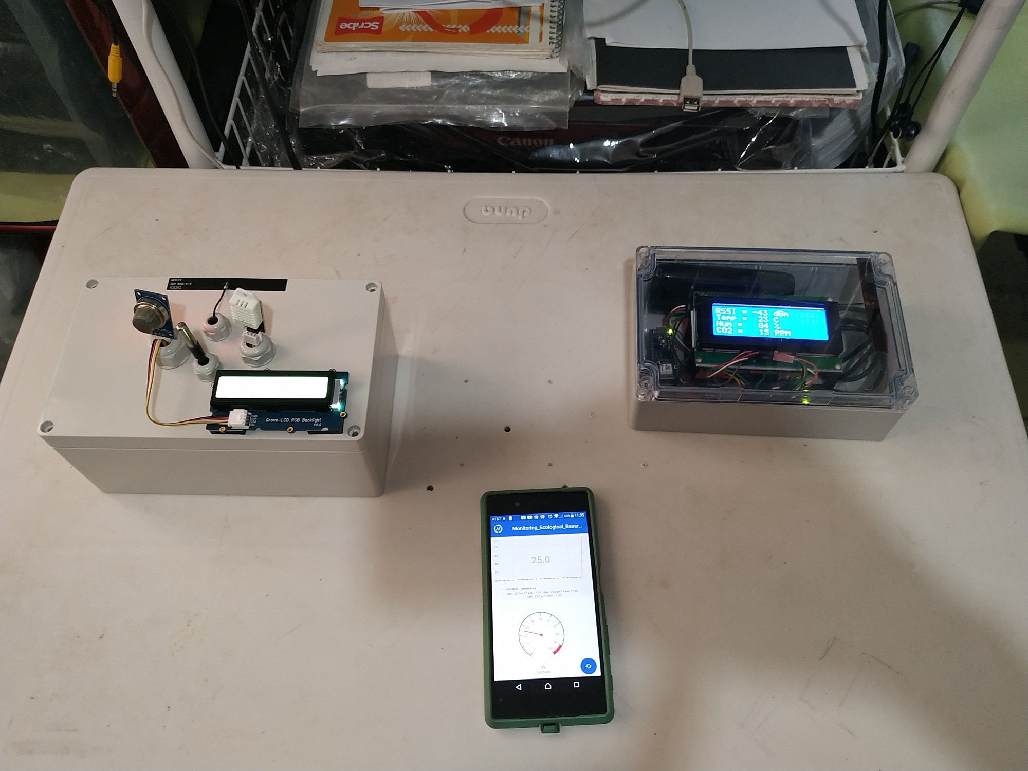
Testing LoRaWAN and IoT Connection
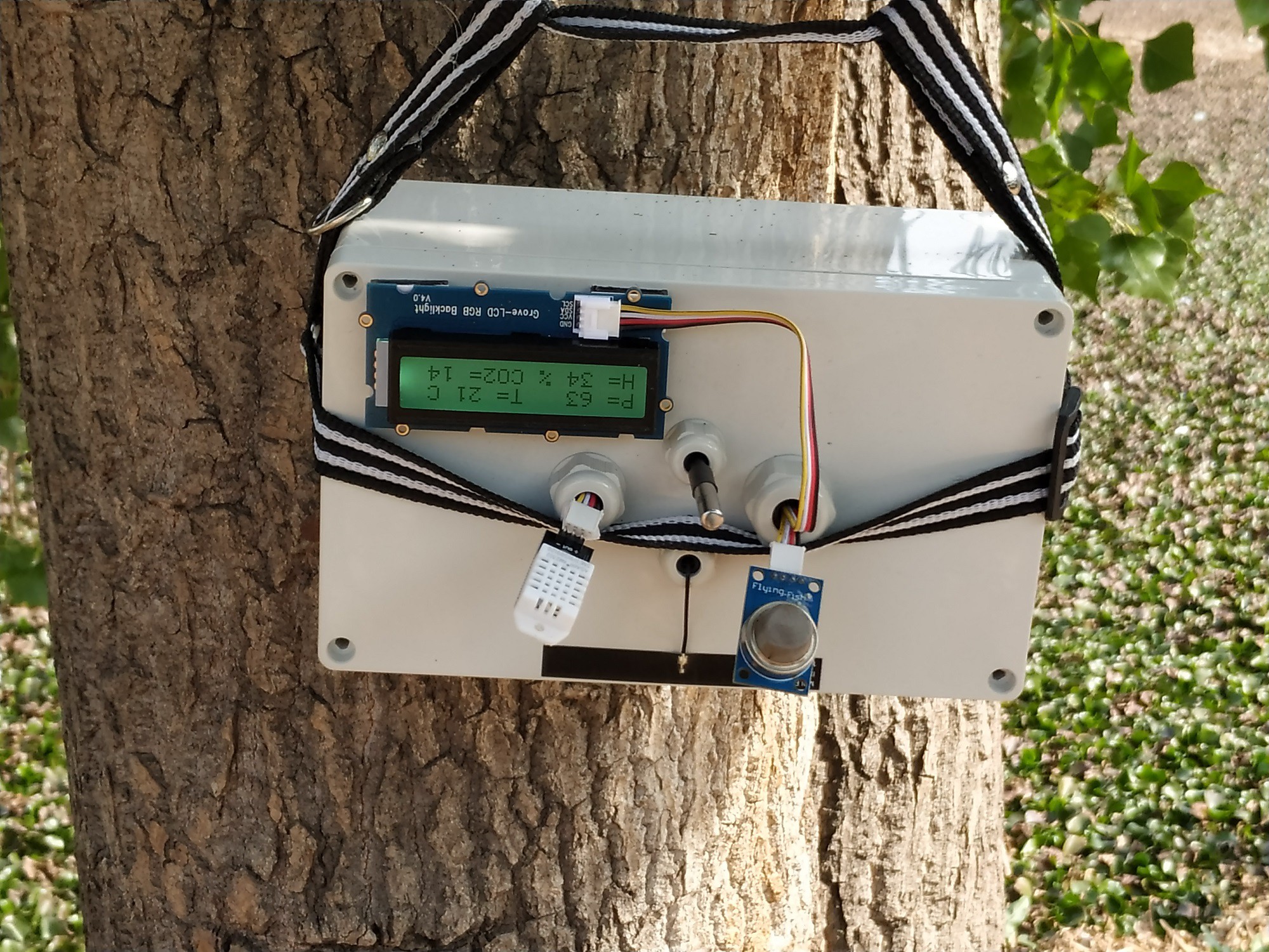
In the final chapter we can see the hardware and software verification tests, as well as the field tests. This was a good experience since I learned to improve the quality of the signal by placing the transmitter module in different trees until getting the best reception.
What next for this project?
The next challenge is to add more features as shown below:
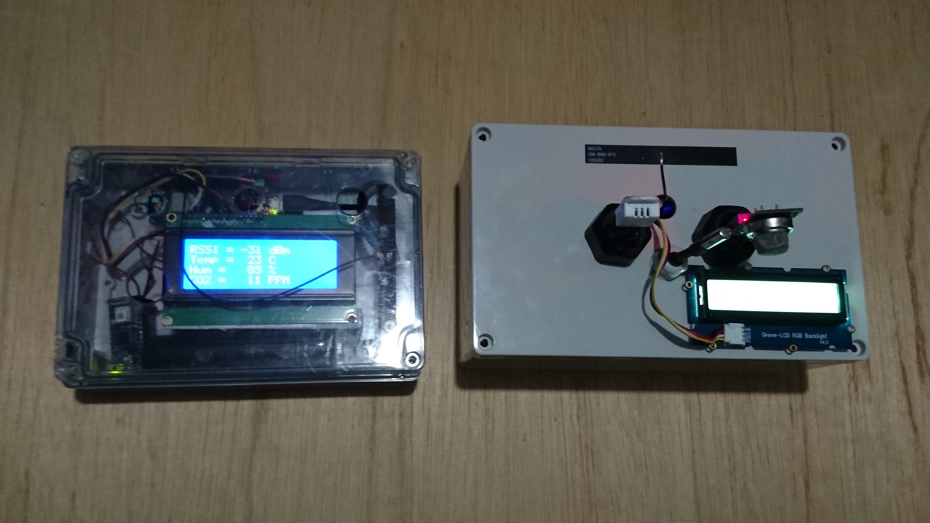
- I have reorganized the transmitter and receiver modules in order to make their work more efficient. In the transmitter module I needed a larger space to connect the solar panel, and anso not bend the antenna too much and avoid the risk of disconnecting it, so I removed the "cable gland", I have also replaced the "cable glands " of the DHT22 and MQ135 sensors for the ones with a larger diameter in order to place here the future sensors that I'm going to add. In the receiver module I have rearranged the programming boards in order to add a higher power battery, I have also added some holes to make connections to the outside either for power supply or for a connection to a PC.
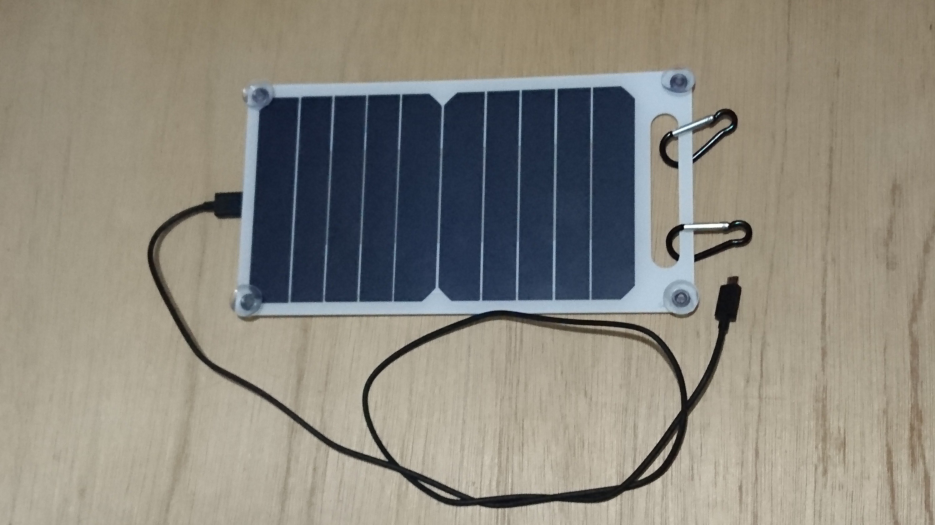
- I'm trying to adapt a solar cell to recharge the battery when the system is on standby mode. Until October 20, I received a 10 watt solar panel charger (Output: USB 5V, 1200mA) by courier. It's ideal for recharging the transmitter battery and doing charging tests.
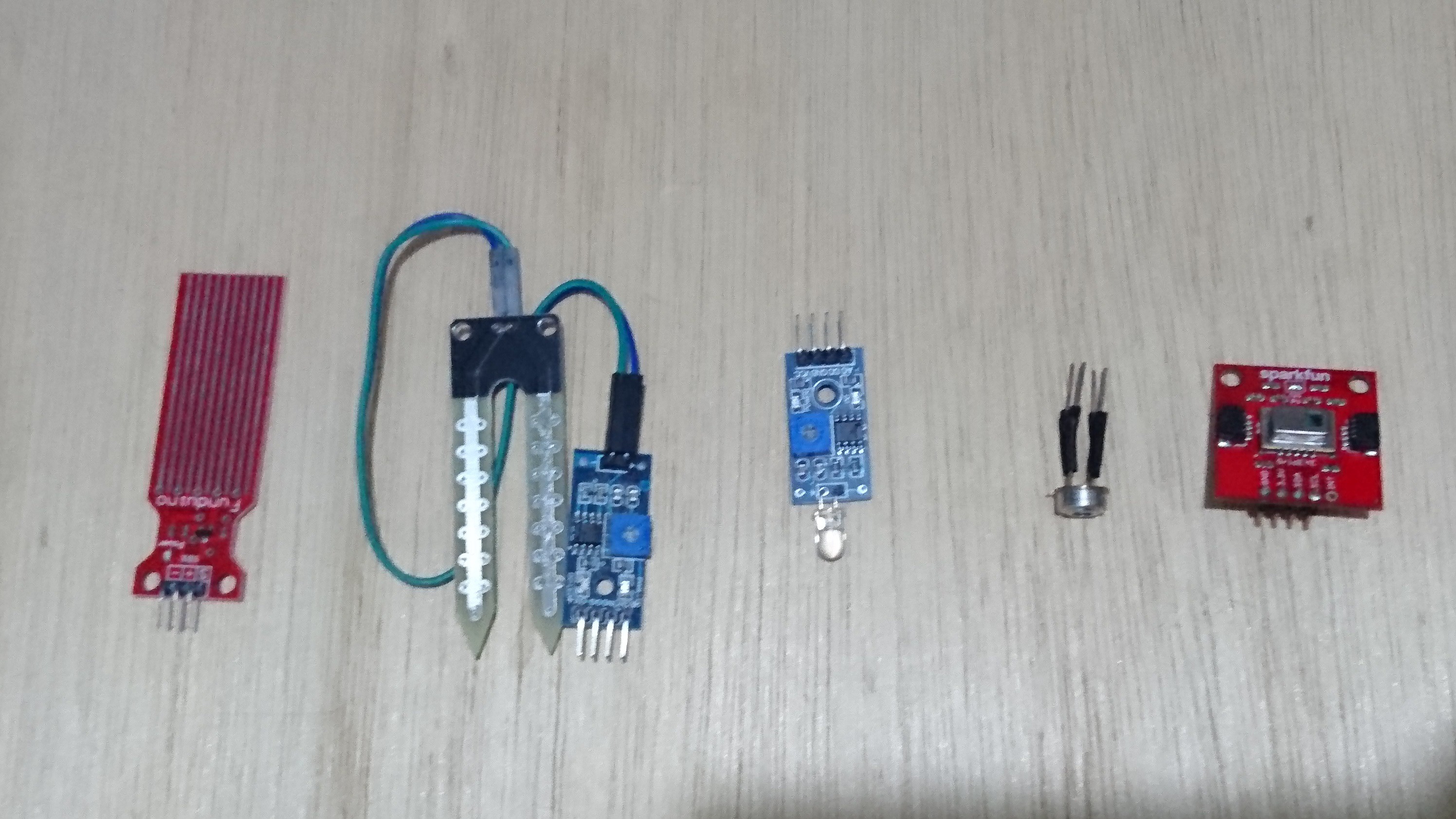
- I'm tryng to add as many sensors to the transmitter module as possible. For example, also I received next sensors: water sensor, soil moisture sensor, flame sensor, Infrared Thermometer - MLX90614, and Infrared Array - AMG8833.
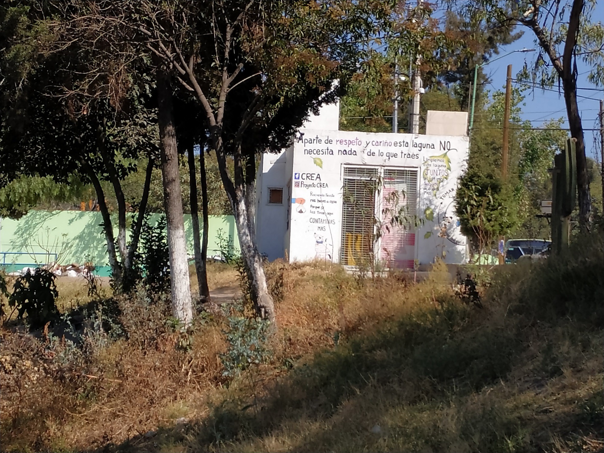
- One important thing is to find a safe area where to monitor our system with the receiver module. To achieve it, I went through the ecological area of my community and found a perfect room module for this task, as shown in the image below. I just have to ask the local authority for permission to do so.
As soon as I can I will publish the new version of my project. Thank you for taking time to read my project.
Discussions
Become a Hackaday.io Member
Create an account to leave a comment. Already have an account? Log In.