 Sagar 001
Most of the power electronics system use big heatsink to dissipate excessive heat. Some of these uses active cooling method, by using a fan on heatsink which help to remain the temperatures more stable. But when running these things on a low power fan is still on and feel noisy. So why not to make a programmable fan which can be turned on when required. Using Arduino and temperature sensor we can make a temperature-controlled fan. More applications of this type of fan can be found in UPS, Inverters, Amplifiers and Bench power supplies.

To make a better demonstration of the project we will design a PCB which based on 12c connections. I am using JLCPCB PCB prototype service for a long time. They are providing best service in just $2 for 5 pcs of multilayer PCB.
Basic Idea:

A temperature sensor (lm35) can be attached directly to the heatsink of the system which reads the temperature. Arduino made some calculations and control the speed of fan using PWM output signal. A transistor can be used as a switch to turn ON/OFF the fan. To make the project more demonstration cooler a screen can also be added which is used to display the temperature and fan speed respectively.
Temperature sensor (Lm35):
The LM35 series are precision integrated-circuit temperature devices with an output voltage linearly proportional to the Centigrade temperature. The LM35 device has an advantage over linear temperature sensors calibrated in Kelvin, as the user is not required to subtract a large constant voltage from the output to obtain convenient Centigrade scaling.

As the LM35 device draws only 60 μA from the supply, it has very low self-heating of less than 0.1°C in still air. The LM35 device is rated to operate over a −55°C to 150°C temperature range
More Features:
Calibrated Directly in Celsius (Centigrade)
Linear + 10-mV/°C Scale Factor
0.5°C Ensured Accuracy (at 25°C)
Operates From 4 V to 30 V
How to read temperature:
Lm35 has a linear 10mv constant per degree, When ever the output of sensor is increased by 10mv the temperature rises 1 degree Celsius. So we can design a code to read the temperature using this method.
First of all using Arduino ADC we can read the value of output voltage.
float voltage = reading * (5.0 / 1024.0);
Then we can turn the output voltage into respective temperature readings.
float temperatureC = voltage * 100;
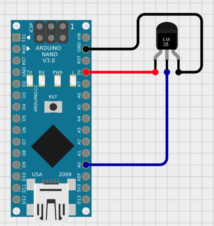
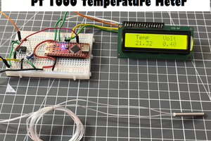
Made all the connections according to the given schematics. To check the temperature constant and voltage output, heat and cold test can be performed. After making the connections with Arduino, upload the code given below. Then open the serial monitor and start performing some test by heating/ cooling.
// Define the analog pin, the LM35's Vout pin is connected to
#define sensorPin A0

void setup() {
  // Begin serial communication at 9600 baud rate
  Serial.begin(9600);
}

void loop() {
  // Get the voltage reading from the LM35
  int reading = analogRead(sensorPin);

  // Convert that reading into voltage
  float voltage = reading * (5.0 / 1024.0);
  Serial.print("voltage:");
Serial.println(voltage);
  Serial.print("ADC VALUE:");
Serial.println(reading);

  // Convert the voltage into the temperature in Celsius
  float temperatureC = voltage * 100;

  // Print the temperature in Celsius
  Serial.print("Temperature: ");
  Serial.print(temperatureC);
  Serial.print("\xC2\xB0"); // shows degree symbol
  Serial.println("C");
 Serial.println("       ");
  delay(1000); // wait a second between readings
}
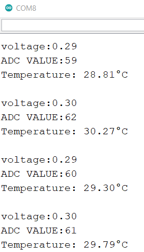
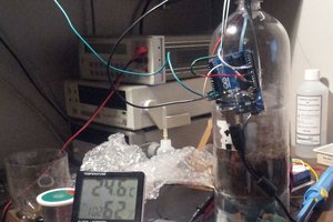
These are some observations I got, at room temperature:
On heating:

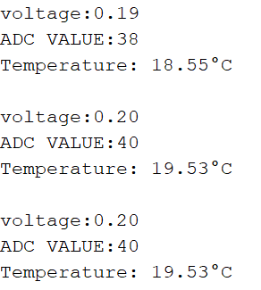
On cooling:
Using the same idea of reading temperature, we can program Arduino to generate a PWM signal. Which then trigger the switching transistor and hence control the fan and fan speed.
Components required:

- · LM35 Temperature sensor
- · Arduino Nano/ Uno
- · CPU fan
- · 9V battery
- · LCD screen 16x2 with I2C
- · 2N2222 switching transistor
- · 1k resistor and 47uf capacitor
- · Connecting...
 Lithium ION
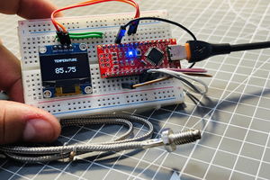
 Darren Blaxcell, aka Pork