-
1Pick a frame
The mirror will sit in a picture frame. The added bonus of a picture frame is it will come with glass that you can adhere the window (mirror) tint to. The size of the frame is really dictated by the size of the image you want to put in it and the length of your LED strip. For my example, I had a skull bas-relief image and it made more sense to just light it up from the bottom to give it a more menacing look.
-
2Construct the frame
There is a million ways to construct a frame, here is just my angle on it. All you really need to consider is the space for the LED strip, the MP3 player, and the controller. The materials log is based on this 6x8 frame.
![]()
Boxing for LED lamps
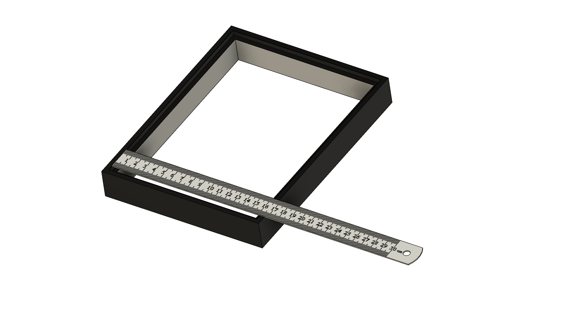
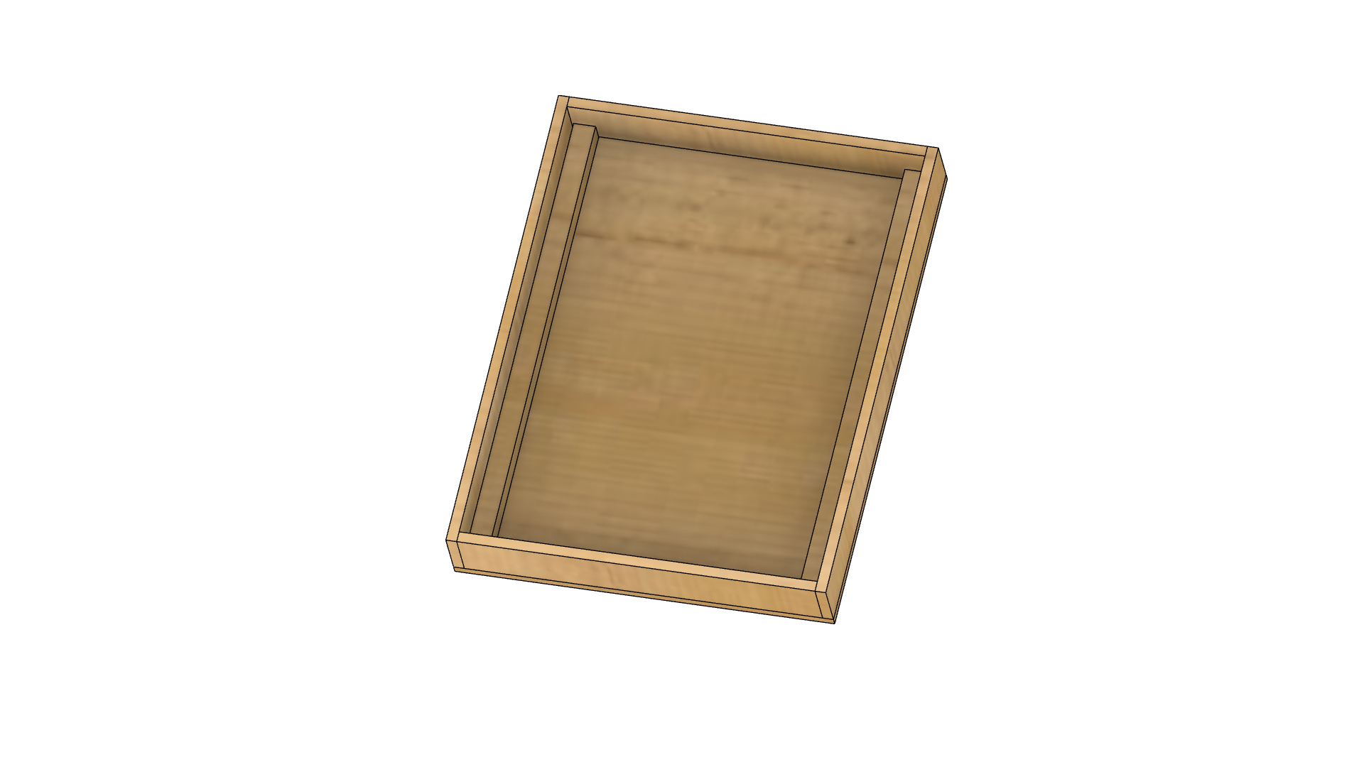
LED strips are usually 10mm wide, here I will make a frame from 10x10 pine trim that fits inside the area the area where the picture usually fits. Measure the inside of the frame (where the glass sits).
![]()
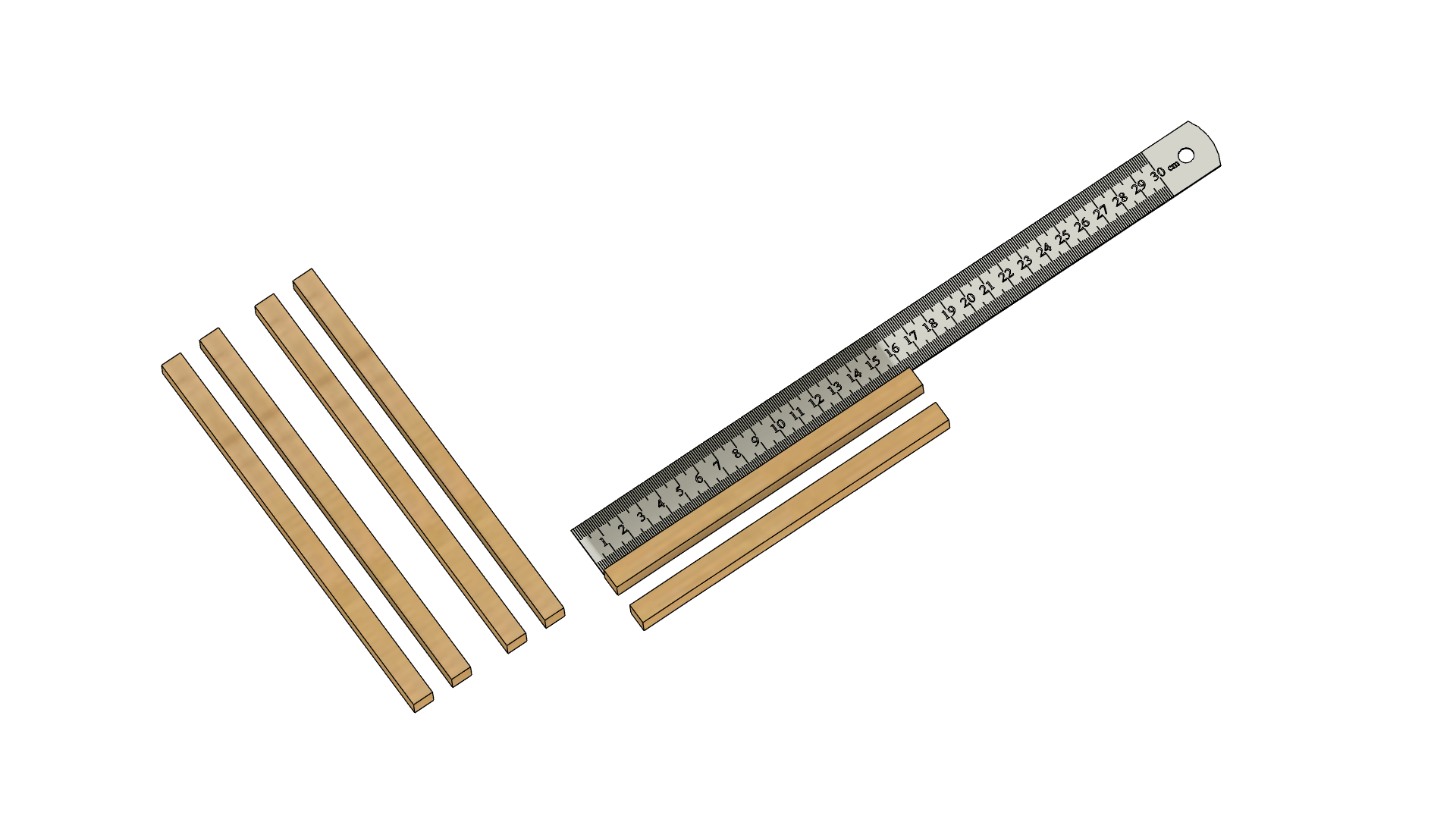
Mark out the pine trim and cut the long sides 20mm shorter as we are making a butt joint. Cut 2 pieces for the short side and 4 for the long side.
![]()
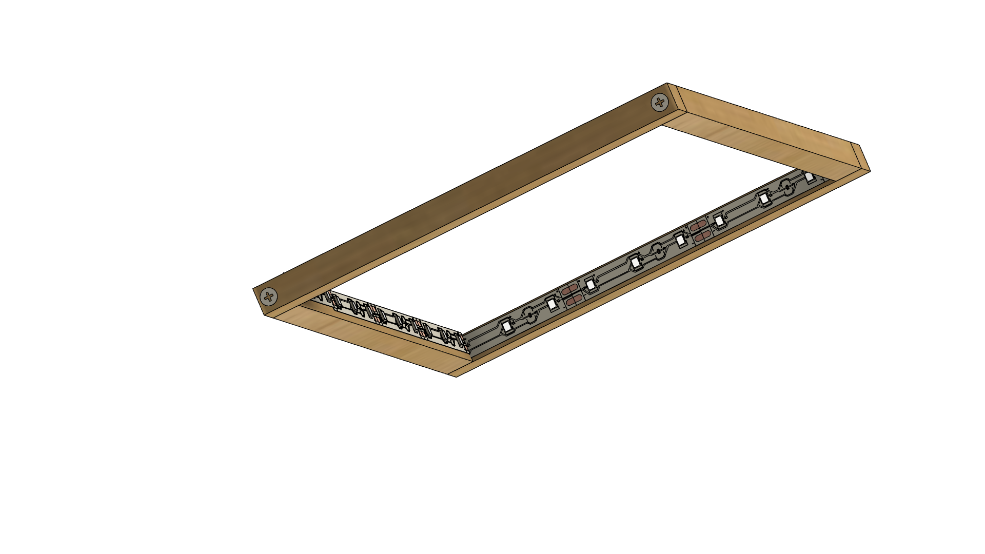
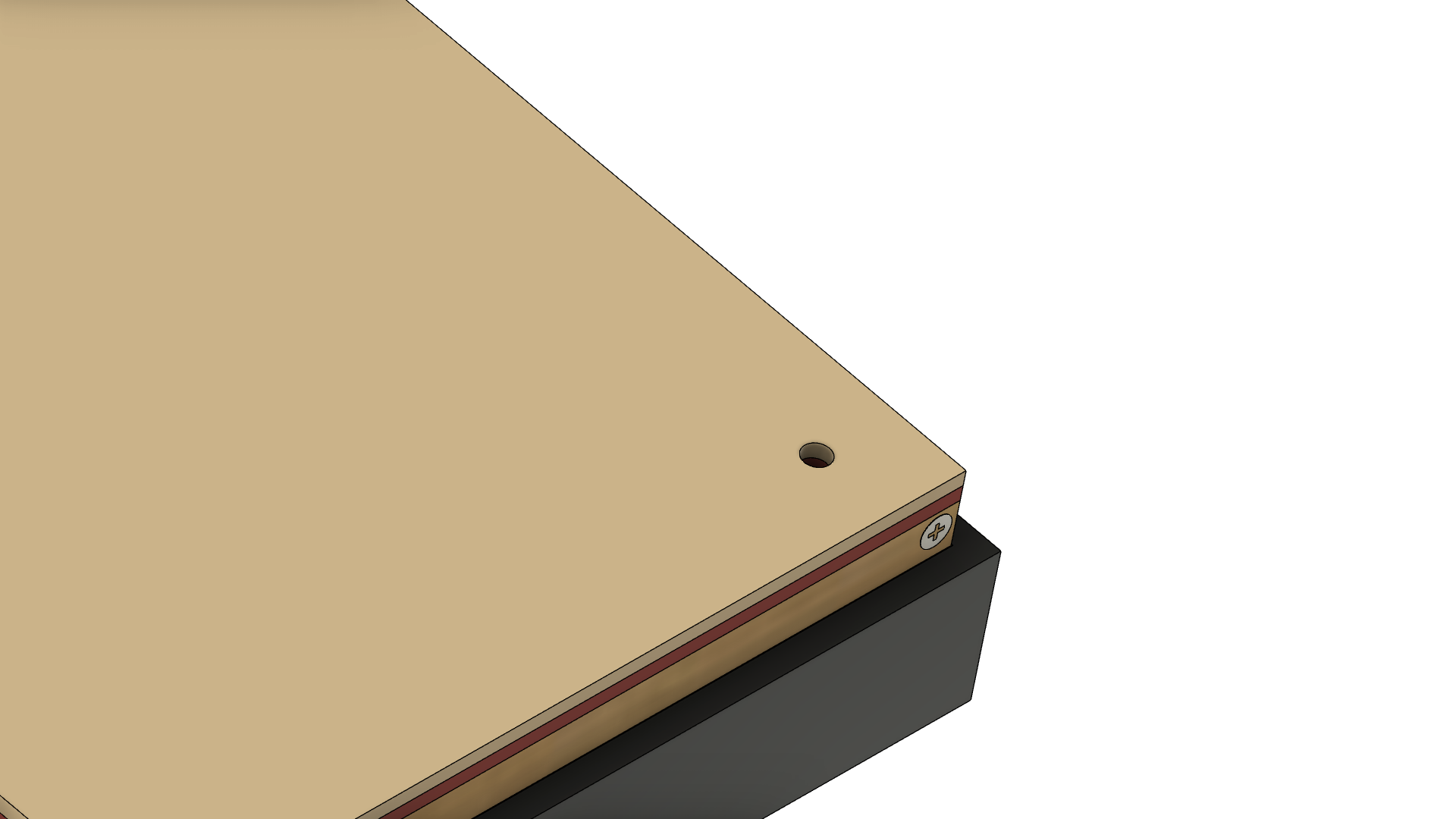
Drill a hole in each long end of pine trim into the end of the short pine trim, and use glue and a self-tapping screw to hold the frame together. Drilling stops the wood from splitting.
Put the surplus long pieces to one side to be used later.
![]()
Once the glue has set apply the LED strips to the inside making sure there is a connection all of the way around. In one corner you will need to run wire to the back of the frame. More on this later.
Assemble the boxing
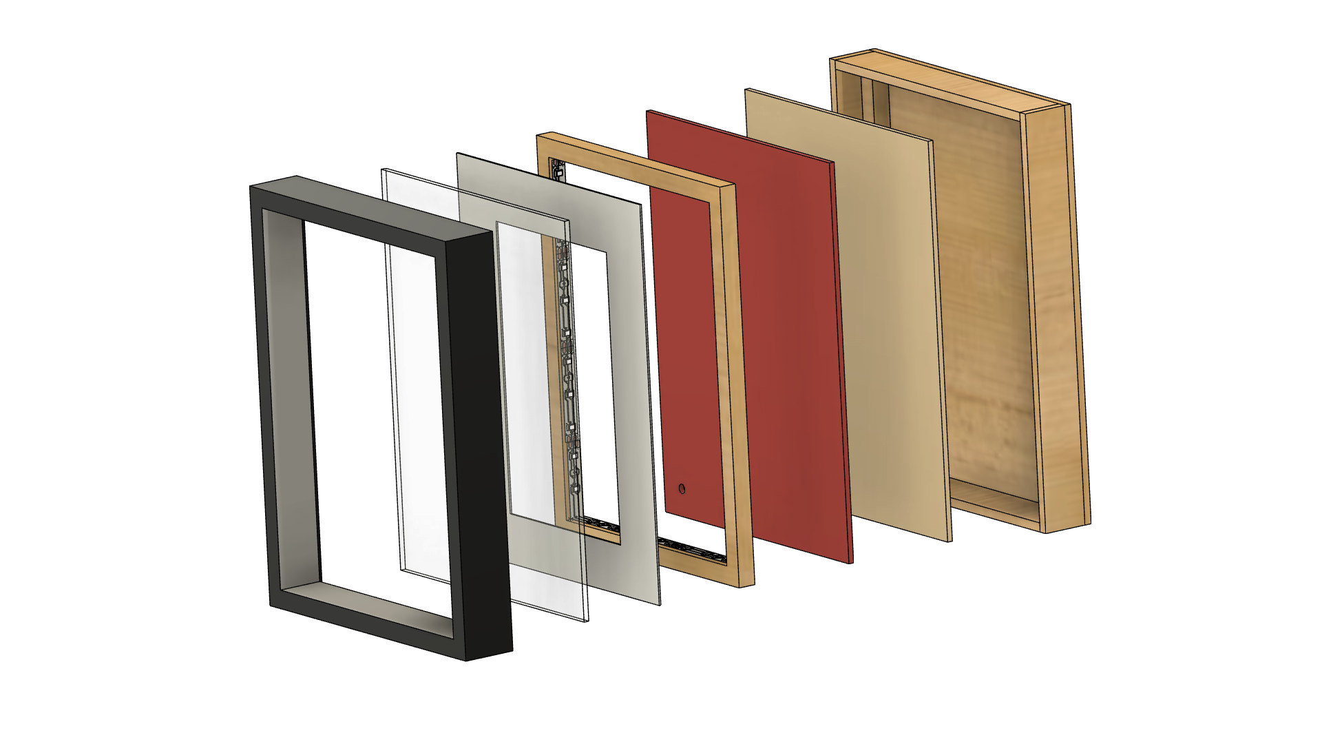
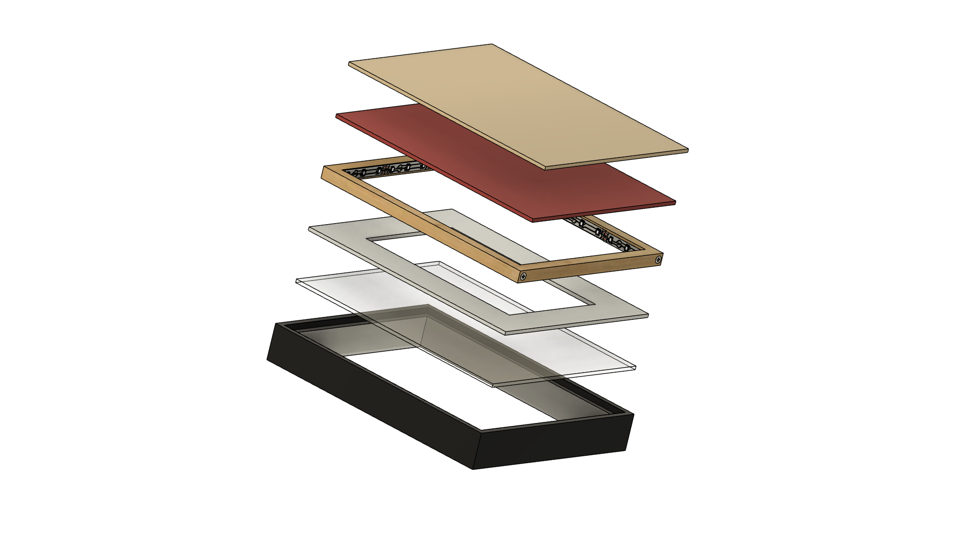
With the LED frame assembled compile all the parts of the frame together in order.
- Picture frame
- Glass
- Mat
- LED frame
- Picture (shown in red below)
- The backing that came with the frame
![]()
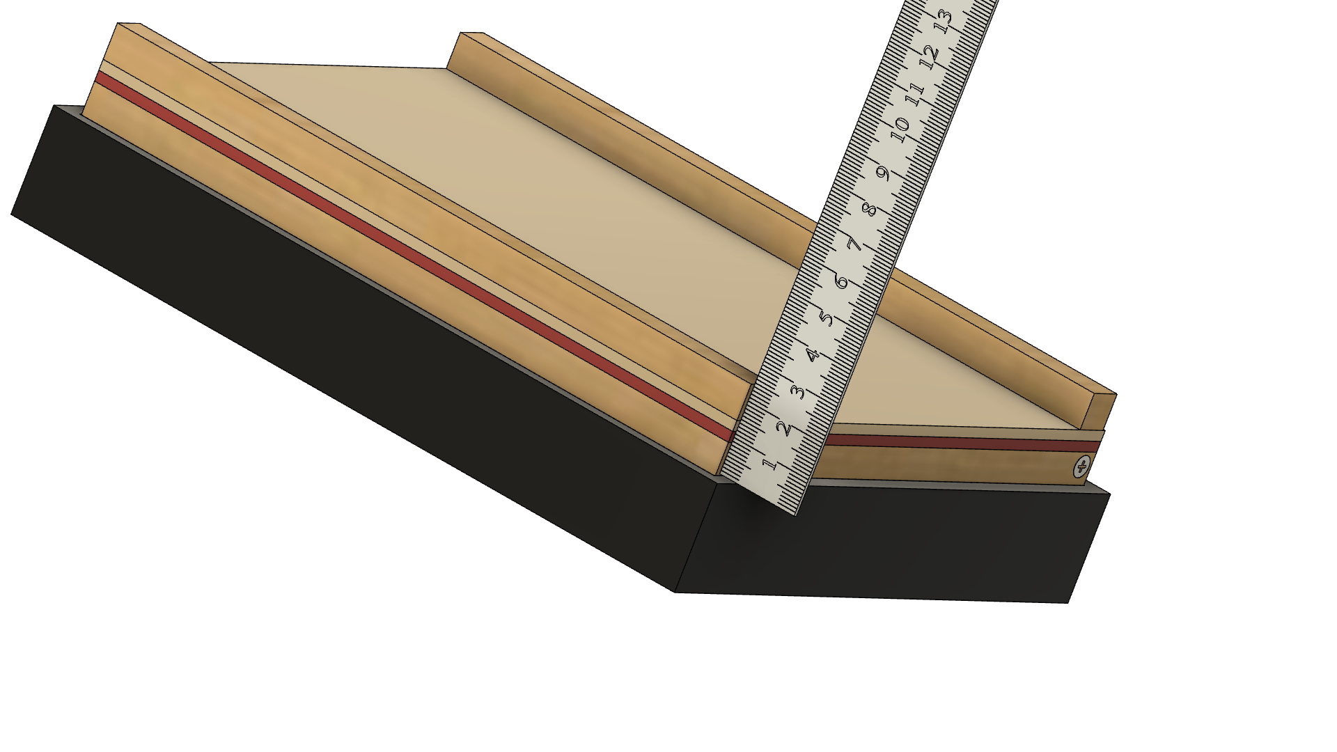
With this compiled add the extra two long pine trims and measure the height from the frame to the top of the pine trim.
![]()
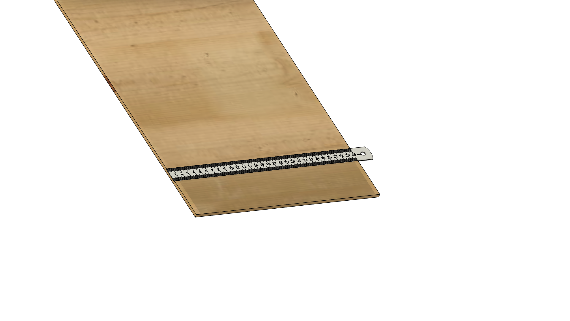
Measure out this distance on some flat particle board or pine (4-5mm thick) the length of each side.
![]()
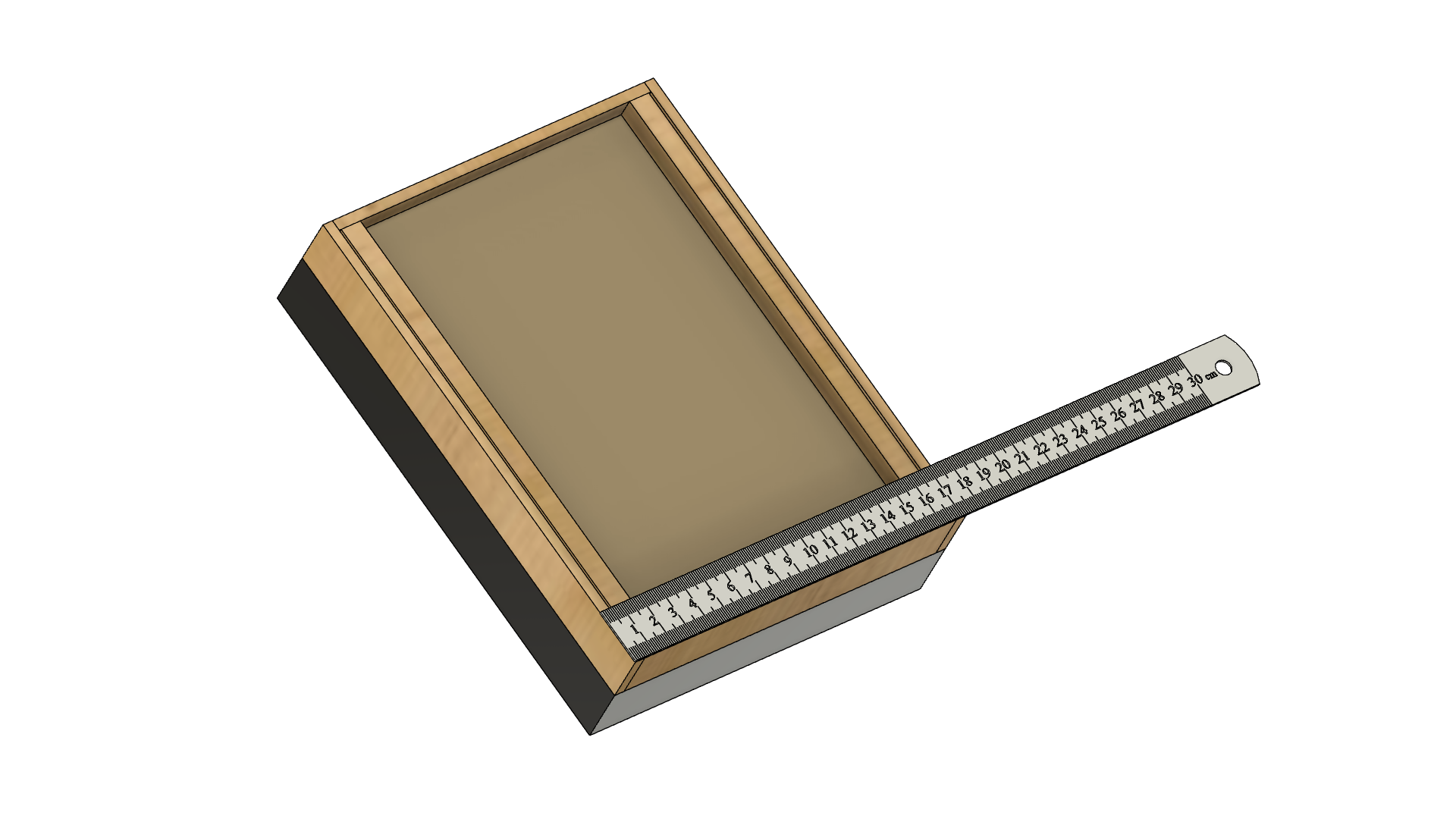
Create a box around the frame, screw, and glue the box together. Measure the width and height and cut one more piece to cover the entire back.
![]()
Assemble the back section of the frame.
![]()
The gap between the back of the frame and the picture will house your electronics.
Drill a hole in the picture and picture back for the wires from the LED lamps to feed through.
![]()
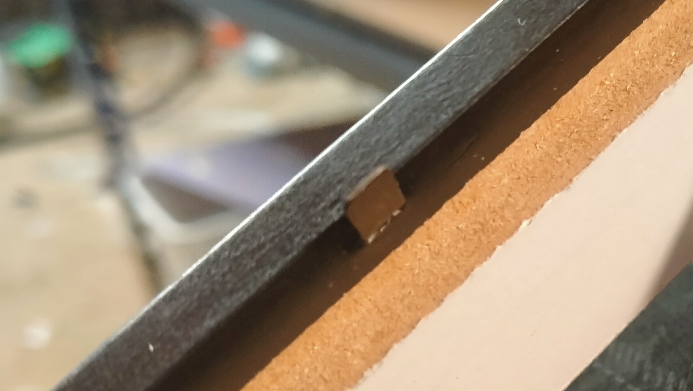
Most picture frames have metal clips to hold the picture in place.
![]()
Mark these positions into the side of the LED frame, then drill holes halfway in for the tabs to hold the frame, matt, and glass in place. The rear frame can slide on and off making it easy to change the picture or service the electronics.
-
3Tint the glass
This is best demonstrated in a video.
-
4Prepare electronics
As mentioned I used a digistump board in my project due to its small size. Any Arduino could be used you might just need to alter the code to match your specific pin arrangement.
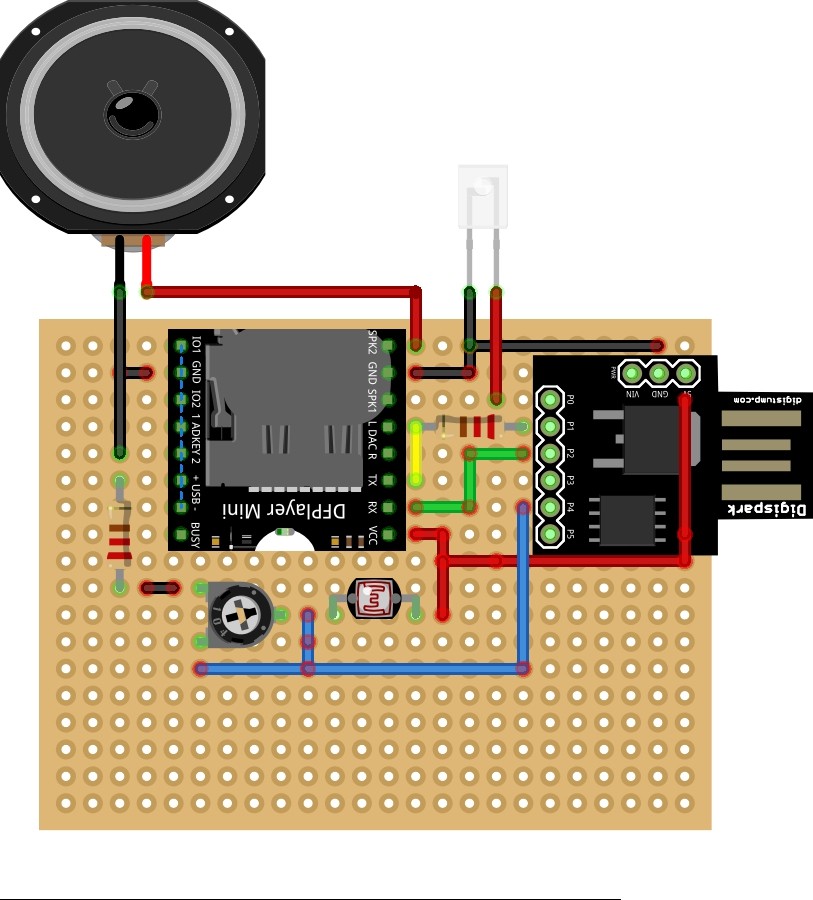
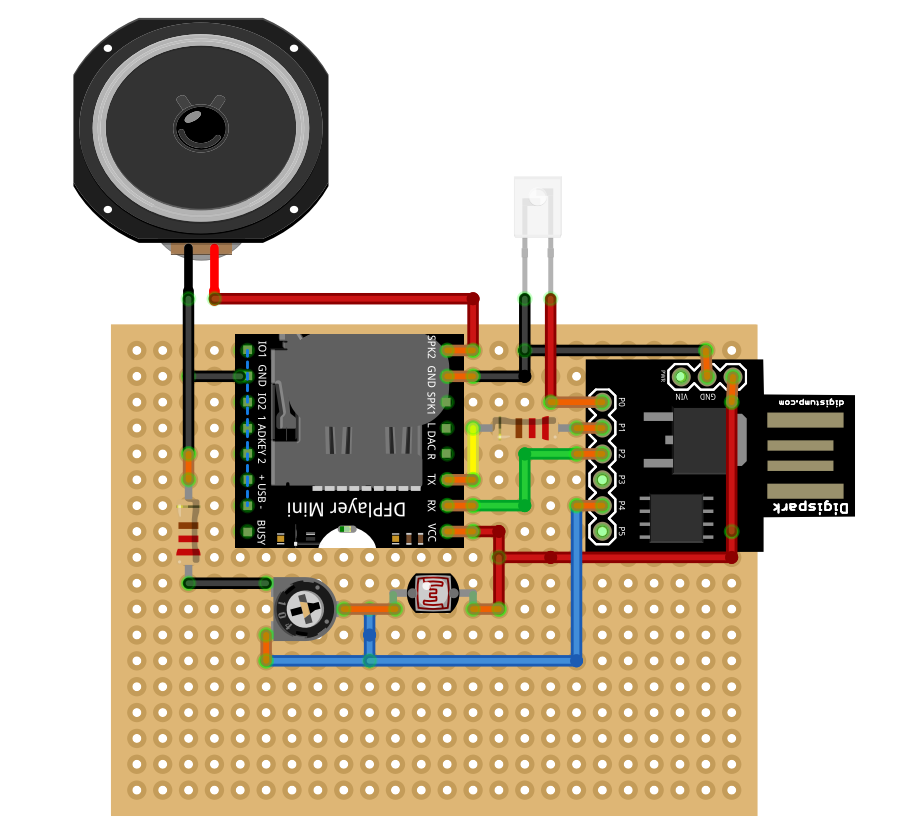
I laid the DFplayer, controller and associated components on a variboard but the components are quite sparse so you could possibly just use hook-up wire.
![]()
This is not a stripboard you can assume the adjacent pin is connected to its nearest pin. See the diagram below, orange connections are joined on the copper side.
![]()
Note: P1 on the controller connects to a resistor and then to the TX pin NOT to the pin marked L DAC. As long as your LED strip is not too long and mono color you can drive it from the board directly. Neopixels would need a driver board to support he current.
The Light Dependant Resistor should be connected to the hookup wire and run to the side of the frame. The LDR will need to be able to "see" the light in the room. It won't work contained in the frame.
-
5Program your contoller.
Here is the sketch I cobbled together to make it work. Disclaimer, I am not a programmer there are almost better ways to complete this task. I salute those that can do better.
#include "Arduino.h"
#include <SoftwareSerial.h>     k
#include "DFRobotDFPlayerMini.h"

// Change the defaults below to match you needs.

// Set the serial pins to the DFplayer here
SoftwareSerial mySoftwareSerial(1, 2); // RX, TX

// The LED lights use PWM to light up and down set this output pin here
int PWM_pin = 0;

// This is the in the light dependany resistor is connected to
int LDRpin = 5;

// how long the light stays on
int onTime = 15000;

// speed of the light up/ light down effect
int dtpause = 30;

DFRobotDFPlayerMini myDFPlayer;
unsigned int randomNumber = 0;

int dimmerLoop = 0;
int darkFlag = 0;
int sensorValue = 0;

int level = 153; // Variable level of brightness of the on phase (0 <= level <= 255)
int L1=10, L2=210, L3=110;

void setup() {
pinMode(PWM_pin, OUTPUT);
pinMode(LDRpin, INPUT);

mySoftwareSerial.begin(9600);
myDFPlayer.begin(mySoftwareSerial);
myDFPlayer.volume(5);  //Set volume value. From 0 to 30 set it louder here if required.
}

void loop() {
sensorValue = analogRead(2);
delay(1000);

if (sensorValue < 300 && darkFlag == 0)
  {
  dimmer();
  darkFlag = 1;
  }
  if (sensorValue > 200)
  {
  darkFlag = 0;
  }
  }

void dimmer()
{
 randomNumber = random(0, 10);
   myDFPlayer.volume(20);
    myDFPlayer.play(randomNumber); //play a random MP3 file

  dimmerLoop=1;
  while (dimmerLoop != 0)
  {
  L1=L1+1;
  analogWrite(PWM_pin, L1);
  delay(dtpause);
    if (L1 == 255)
      {
      delay(onTime);
      while (L1 > 0)
        {
        L1=L1-1;
        analogWrite(PWM_pin, L1);
        delay(dtpause);
        }
      dimmerLoop=0;
      }
  }
  return;
}
The code is simple, It waits for the analog reading from the LDR to drop to a threshold and then kick-off the player and light circuit. The light will not go on again until it is reset by the lights in the room coming on again.
-
6Operation
Assemble all components in the frame in the correct order.
With your frame assembled make sure the LDR is outside of the frame glued on the side.
![]()
I replaced the back of my frame with a PLA plate with speaker holes. A guide to making easy speaker holes in Fusion 360 can be found here.
The DFplayer requires that the files be named in an nnnn.mp3 format. You must have a 4-digit number 0000 - 9999 at the beginning of the file name. The first sound should be 0001.mp3 and so on. The sketch as it is will play 10 different MP3. If you want the sound to always be the same copy the file 10 times and name them 0000.MP3 to 0009.MP3 if you only have one file the sound may play only 1 in 10 times.
Attach your power source. For mine, the controller had a USB plug so it was just a case of sliding the battery on. If you are using a mains adapter you should connect to the ground and VIN on this controller. Any other Arduino could be supplied via the USB port.
Situate the frame where you think it will be used and check when turning the light on and off if the sound and LEDs come on. If not adjust the variable resistor to match your environment. Further tweaking can be made to adjust the value in the `if` statement in the sketch if required.
Now go scare someone!
Halloween Mirror
Scare the bejesus out of friends and family with this innocent looking mirror
 jasonwinfieldnz
Discussions
Become a Hackaday.io Member
Create an account to leave a comment. Already have an account? Log In.