 Emilio P.G. Ficara
Single 3.7V Li-ion cell battery back-up for Raspberry Pi
I have a small application continuously running on Raspberry Pi board. Sometimes, in my country, we have (short time) mains power failures. In such situation, my Raspberry board, powered by the wall adapter, turns off immediatly, without any attention for open files, transmissions in act, etcetera. This is really a problem. I decided to use some materials purchased online in the past to realize a small power back-up unit, using a single Li-ion cell. First of all, you need for a battery charger circuit, to maintain the back-up battery fully charged. The battery is 3.7V typical, and 4.2V when fully charged, but the Raspberry Pi board wants 5V supply, so we need for a Step-Up circuit. As third element, we need for a switch that disconnects the load from battery when mains supply is present, ‘cause the charger can’t see the real battery level if you connect a load while charging. I suggest to read this document released from Microchip: AN1149.
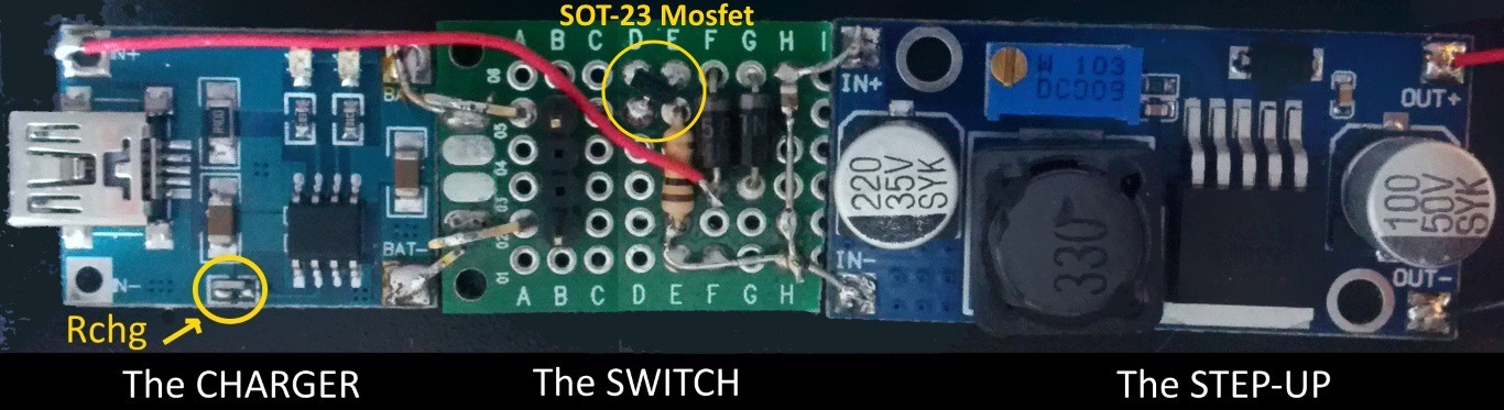
The charger can be easily found online searching for “1A Li-ion battery charger”. It’s based on well known chip named TP4056. In the picture there is a circle indicating Rchg. The component circled is the charge resistor. The value of such resistor sets the charging current. In the original circuit, the value of Rchg was 1K2 (smd mark 122) that sets 1A charge current. I removed such resistor and placed a new one with value 3K3 (smd mark 332). With this resistor, the charging current will be about 370 mA. I don’t want to charge the battery at higher rate for two reasons: the first is the capacity of the cell (I used a small one), the second is that the wall adapter MUST have enough current to drive the charger AND the Raspberry Pi board. In the next picture you can see three different situations:
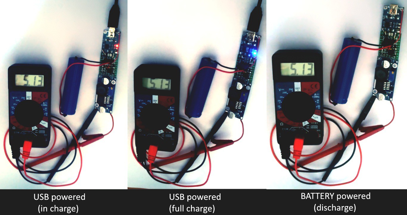
Starting from the left, you can see the circuit connected to the wall adapter and the battery charging (red led ON), then the battery fully charged (blue led ON), then the wall adapter has been removed (both leds OFF). Note that the multimeter measures 5.13V in all cases.
The step-up module can be found with a search online, looking for step-up regulator with variable voltage (mine is based on recent XL6009 chip). The XL6009 regulator is rated for Vin_min = 5V, but I tested that works with 3.5V. For best operative conditions, look for a step-up module that mounts an LM2577S-ADJ chip, that is rated for Vin_min = 3.5V. Note that you must trim the variable resistor to have 5V output. Please, connect a 1K resistor as load to the output when setting the Vout, ‘cause there is a capacitor that remains charged when you turn the trimmer decreasing the output voltage. After setting, remove the load resistor.
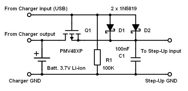
The switch element cannot be purchased online (sorry) and you must build it by yourself. I started from the circuit proposed in the Microchip’s application note and just modified something. For the P-channel mosfet, I used a free sample received from NXP: the PMV48XP. This SOT23 mosfet is very small (look at the picture “The SWITCH”), but it’s really powerful. I used two 1N5819 Schottky diodes (not one) to reduce the voltage drop and increase the current. The circuit is very simple:
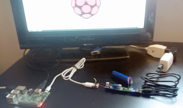
And finally, look at the next picture. The circuit is connected to my Raspberry Pi board. In the animation you can see that the board doesn’t turn off when the wall adapter is disconnected. The time of back-up depends from the capacity of the cell that you use. Remember that the current drawn from the battery (when wall adaptor is disconnected) is the nominal current of the Raspberry Pi board multiplied for the efficiency of the step-up in converting from Vbat to 5V.
Test report
Test conditions: battery fully charged, Raspberry Pi running Raspbian Wheezy and connected to HDMI monitor and to USB interface for RF keyboard and mouse. No other applications running, just the desktop and the default services. I disconnected the wall adapter exactly at 17:17 .
Test results: the battery discharged from 4.2V to 3.7V (about 20% of residual charge) at 18:18, so in about 1 hour.
Please, note that a 3.7V cell must never be fully discharged. If the cell goes below 2.2V, it will probably not recharge anymore. If the cell is “protected”, probably has an electronic switch that disconnects the battery itself from the load when such limit is reached, but if it is a “pure” cell, you must avoid the undervoltage condition.
Questions and answers:
Email – 06/03/2016 – 15:26 from Max:
I am using the same TP4056 charger as you, just with a 240mah lipo battery (with built in protection circuit) I want to do more or less that you are describing, but power outages are very rare where i live. will it potentially harm the battery that it will be kept fully charged all the time?
The charging IC “disconnects” or “floats” the battery at the end of the CC/CV cycle, so when 4.2V is reached and the current flowing into the battery is less than C/10, where C is the current programmed via the R_chrg resistor. If you use 240 mA battery, modify the standard R_chrg on your TP4056 charger circuit in order to set the charge current to about 120 mA (battery C/2).
I am still very new to selecting more advanced components, but will i be able to use an AO3401 mosfet (http://www.aosmd.com/pdfs/datasheet/AO3401.pdf) instead of your example? I can see that the GATE voltage is rated at +-12v which is the same as the PMV48XP, but the AO3401 is rated at 30v/4A and i dont really know what other characteristics is important to selecting the right mosfet?
I looked at the AO3401 datasheet and it seems to be right for this use.
Also, this might seem a bit stupid, but i dont understand why you use 2 diodes. Is the reason that they both have a inner resistance and putting them in parallel basically halves this resistance? Could you just have selected another diode ? And since i am using a small 240mah battery should i still use two diodes? (i see that the AN1149 document mentions a lower voltage as a positive, so i am guessing that low drop is always good here)
You are right, I used two low-drop Schottky diodes to obtain a “very-low-drop” diode. If you have a “natural born” very-low-drop diode, you can use just one.