 Lithium ION
While working on a home automation project on light, the light intensity unit- lux (lumens per square) comes to my mind. Summarizing, while light output is expressed in lumens, light intensity is measured in terms of lumens per square meter or lux. Both the units are different from each other. Let’s have a basic idea about them.
Lumens (Lm) are the unit of measurement we use to quantify the amount of visible light the human eye can see. The luminous flux of a particular light source is measured in lumens. You may have noticed the lumens output printed on led bulbs available in market. More the lumens more will be the light intensity, spreading power and vice versa.
Lux is simply the unit of measure used to describe the number of lumens falling on a square foot (foot candles) or square meter (lux) of a surface. This project is sponsored by PCBWAY.com, china based PCB manufacturer, you can avail the services of this manufacturer at any place of the world at any time in reasonable prices.
LUX measuring sensor:
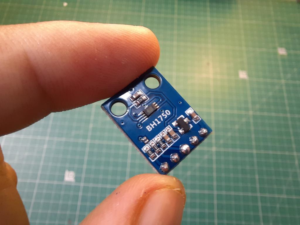
BH1750FVI is a digital Ambient Light Sensor IC for I2 C bus interface. This IC is the most suitable to obtain the ambient light data for adjusting LCD and Keypad backlight power of Mobile phone. It is possible to detect wide range at High resolution ( 1 - 65535 lux ). Which proves the 16bit interface of this IC.
Extra Features:
Low Current by power down function
Low Current by power down function
Small measurement variation (+/- 20%)
The influence of infrared is very small.
It is possible to select 2 type of I2 C slave-address.
BH1750 address and modes:
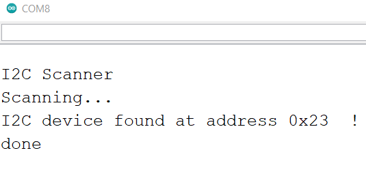
ADD pin is used to set sensor I2C address. If it has voltage greater or equal to 0.7VCC voltage (e.g. you've connected it to VCC) the sensor address will be 0x5C. In other case (if ADD voltage less than 0.7 * VCC) the sensor address will be 0x23 (by default).
- 0x23 (most common) (if ADD pin had < 0.7VCC voltage)
- 0x5C (if ADD pin had > 0.7VCC voltage)
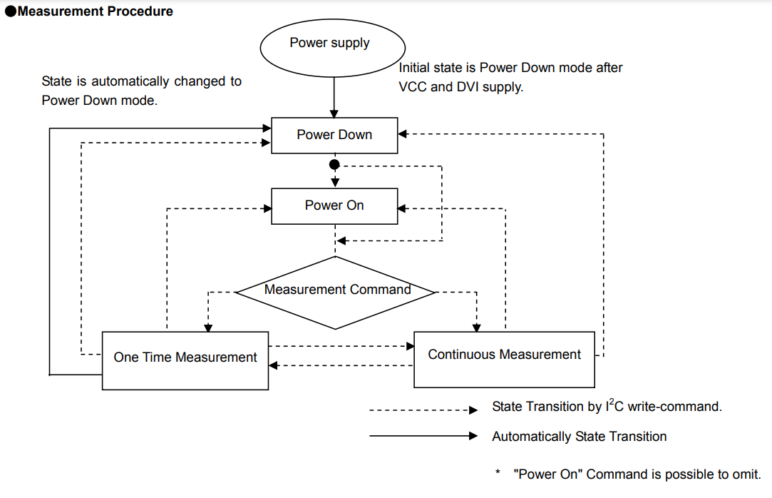
BH1750 has six different measurement modes. They are divided in two groups; continuous and one-time measurements. In continuous mode, sensor continuously measures lightness value. In one-time mode the sensor makes only one measurement and then goes into Power Down mode.
Each mode, has three different precisions:
- Low Resolution Mode - (4 lx precision, 16ms measurement time)
- High Resolution Mode - (1 lx precision, 120ms measurement time)
- High Resolution Mode 2 - (0.5 lx precision, 120ms measurement time)
By default, the library uses Continuous High-Resolution Mode, but you can set any other mode, by passing it to BH1750.begin() or BH1750.configure() functions.
[!] Remember, if you use One-Time mode, your sensor will go to Power Down mode each time, when it completes a measurement and you've read it.
Components required:
1) BH1750 sensor
2) Arduino NANO/UNO
3) 12C LCD 16X2
4) Connecting wires
5) Battery
6) Custom PCB (PCBWAY)
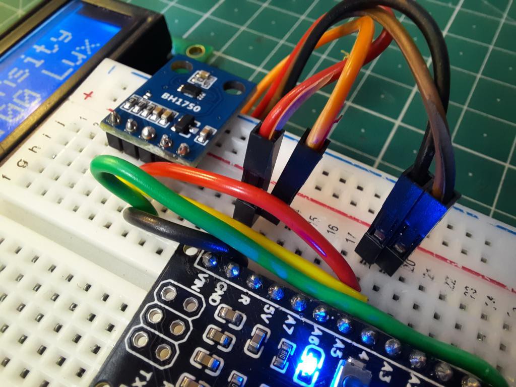
Circuit diagram:
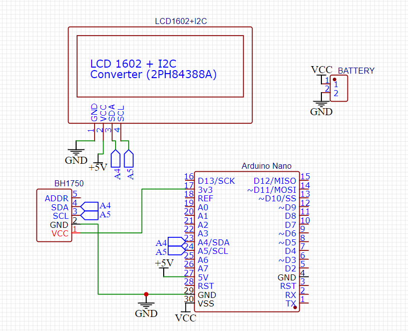
Both the sensor and screen works on 12c scheme, so microcontroller need different 12c address to work with these devices. The code explains the everything about circuit behaviour. All the circuit can be powered using 9v battery. Uno/Nano has 3.3volt, 5volt voltage regulators to operate the sensor and lcd simultaneously.
Connections:
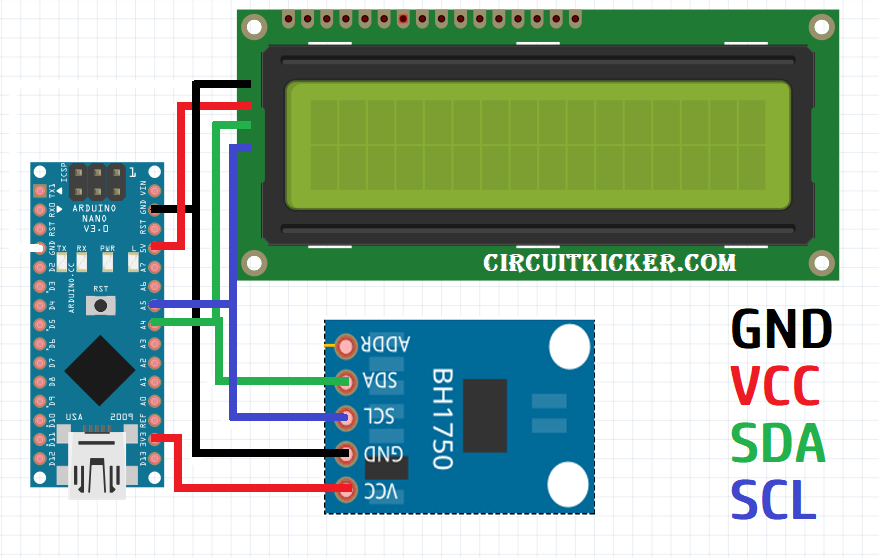
VCC to 3V3 or 5V
GND to GND
SCL to A5
SDA to A4
ADD to (not connected) or GND
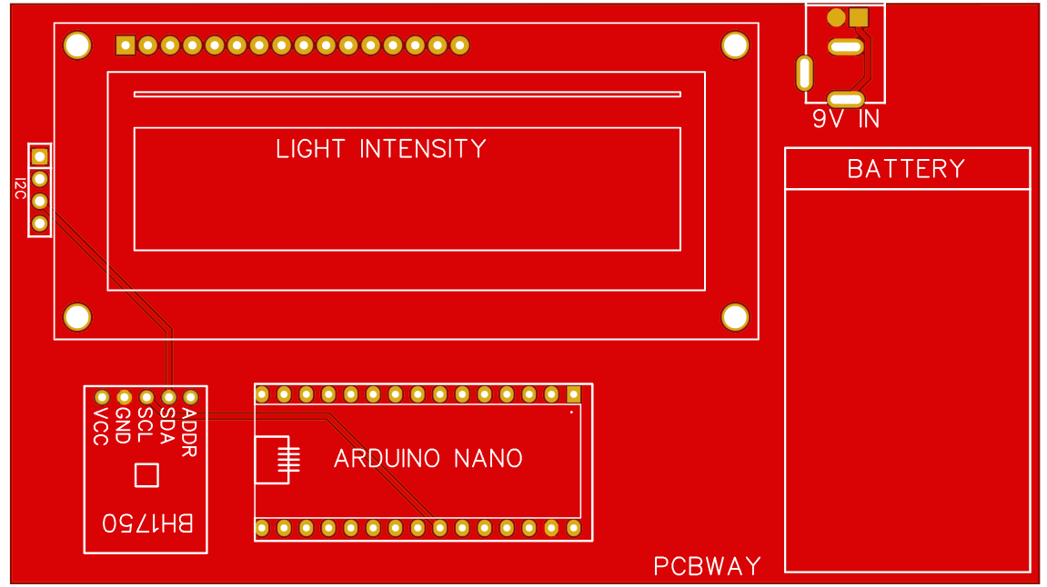
PCB files:
I updated the circuit and turn the schematics into PCB, You can download this PCB shield from here. All the components can be attached to the headers given on PCB and after uploading the code, attaching the battery our project is ready to go.
I always order my files from PCBWAY.COM, They offer different types of PCBs such as Rigid, single layer, double layer, multilayer PCBs with high quality, and reasonable price. They also offer a broad spectrum of assembly, design, and CNC/3D printing services across five factories. Sign-up using this link and get free new user PCB coupons.
Code:
// Full mode list:
// BH1750_CONTINUOUS_LOW_RES_MODE
// BH1750_CONTINUOUS_HIGH_RES_MODE (default)
// BH1750_CONTINUOUS_HIGH_RES_MODE_2

// BH1750_ONE_TIME_LOW_RES_MODE
// BH1750_ONE_TIME_HIGH_RES_MODE
// BH1750_ONE_TIME_HIGH_RES_MODE_2

#include <BH1750.h>
#include <Wire.h>               // Library for I2C communication
#include <LiquidCrystal_I2C.h> // Library for LCD

BH1750 lightMeter;
LiquidCrystal_I2C lcd = LiquidCrystal_I2C(0x27, 16, 2);

void setup() {
  Wire.begin();
  lightMeter.begin();
  lcd.init();
  lcd.backlight();
  lcd.setCursor(0,0);
  lcd.print("BH1750 Test");
  lcd.setCursor(0,1);
  lcd.print("Please wait...");
  delay(3000);
  lcd.clear();
}
void loop() {
   lcd.clear();
   lcd.setCursor(0, 0);
   lcd.print("Light Intensity ");
   lcd.setCursor(5, 1);
   float lux = lightMeter.readLightLevel();
   lcd.print(lux);
   lcd.print(" Lux");
   delay(2000);
}
Libraries used:
In the above given Arduino program, 2external libraries are used. Which can be installed from manage libraries section under tools menu. Wire is a basic and very common library used to setup a communication between I2C devices.
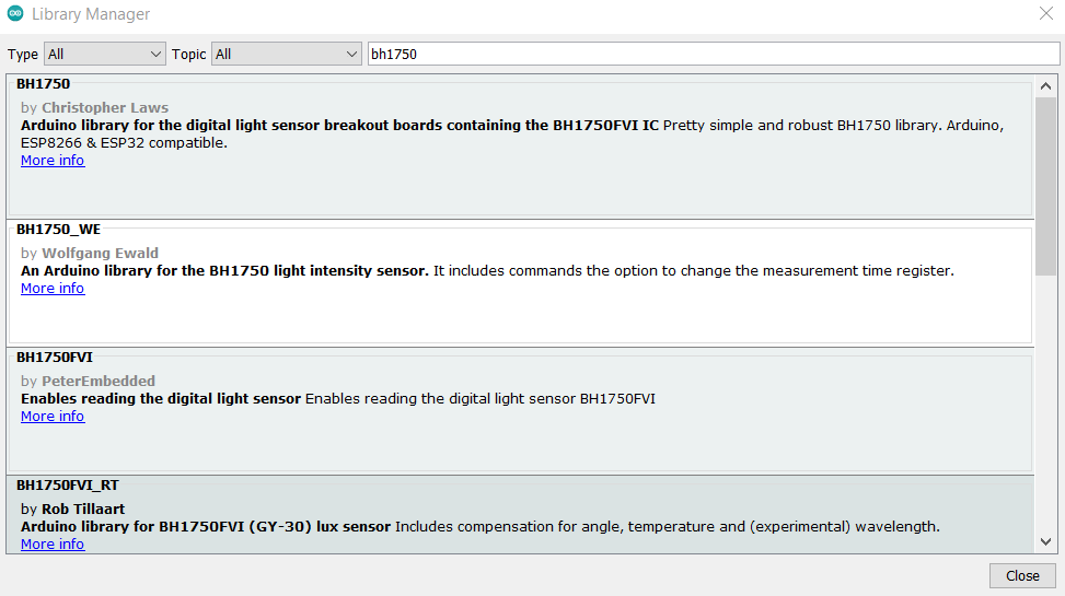
BH1750 and LiquidCrstal_I2C are the two libraries which can be downloaded from Arduino IDE.
Working:
You can measure the light intensity of outside/inside then make a desirable code for your electronics to behave as per it changes. Comparing this with an LDR is quite easy. But in LDR an analog system works which is not too much accurate as digital.
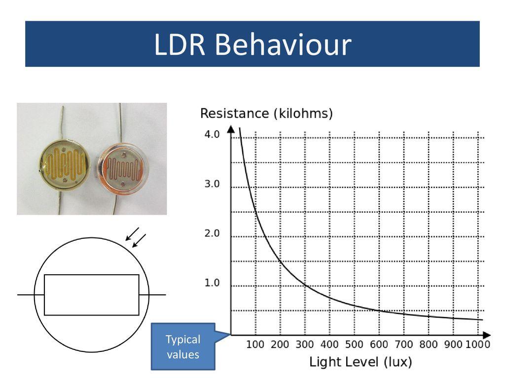
LDR resistance depends on light and gives a non-linear curve, it cannot measure intensity after a level, because resistance decreases too much after that. Don't forget to Sign-up on PCBWAY.com to get 1st service in free.