 Eric Ljungquist
Introduction:
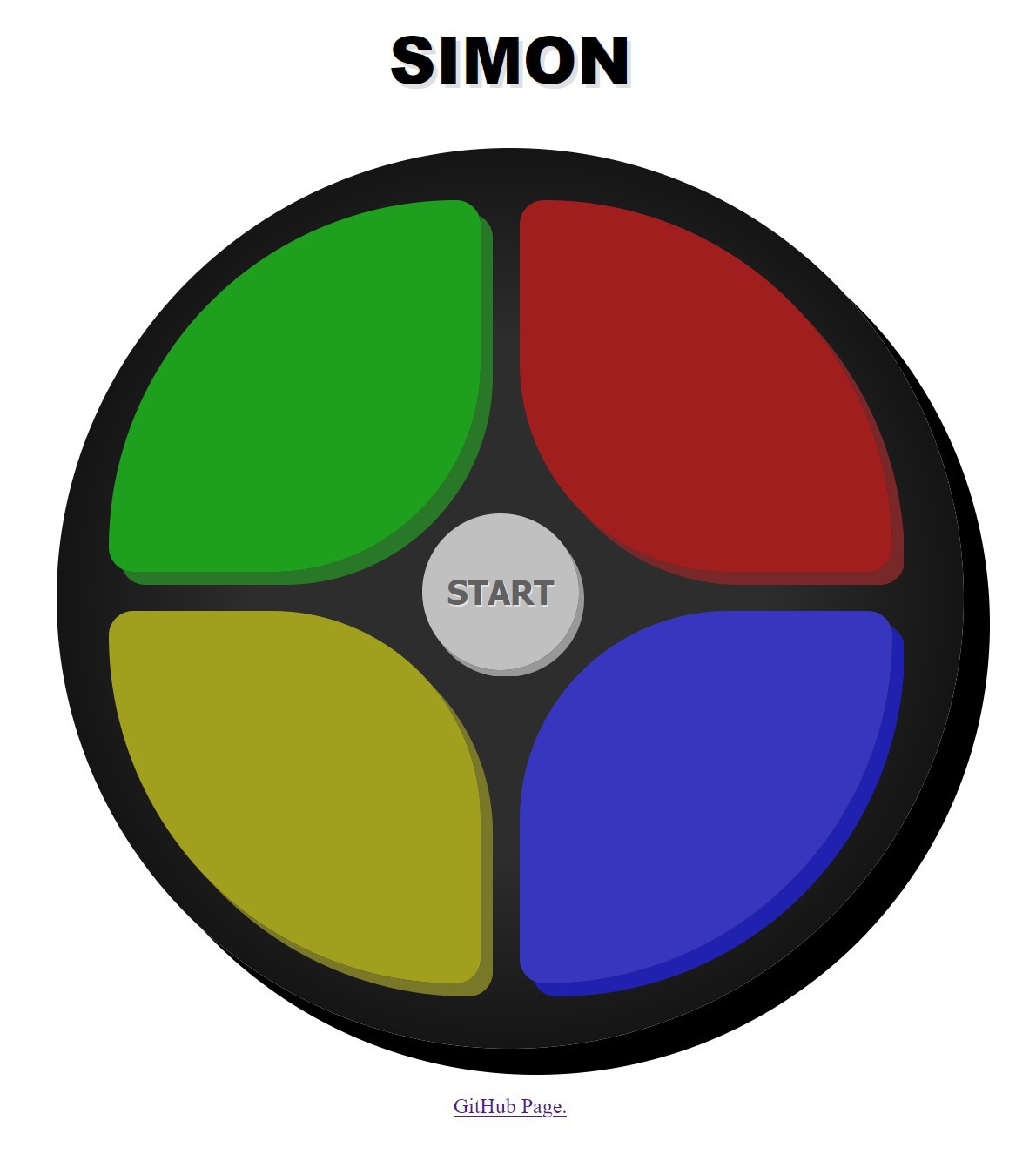
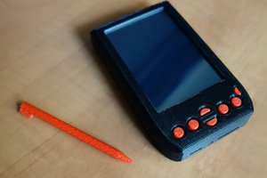
Here's a demo video showing the Simon card running. You insert a 3 volt coin cell battery, A CR2032 works best. Then click any button to start a new game. The player repeats the sequence of tones given by the card with one tone being added by the card on every level passed. If the wrong tone is entered then the player has lost the game.
Getting Started:
I like making web-browser mini-games in JavaScript. So the first thing I did was to create a little demo game to better understand how the project would develop. I abused Promises/Async/Await in JavaScript to make the programming style as linear as possible to simulate how it would run on a microcontroller. This allowed me to quickly translate the code into C when moving on to programming the hardware version. You can click the picture below to open this little demo game in a new tab.
I then began working on a breadboard version to flesh out the hardware. The below video is a demo of this breadboard version. The ATtiny212 on the green board on the left is doing the actual processing. The Arduino is acting as a and power source.
Construction:
The main constraints I wanted to follow were to reduce the number of components as much as possible and keep the card as thin as I could.
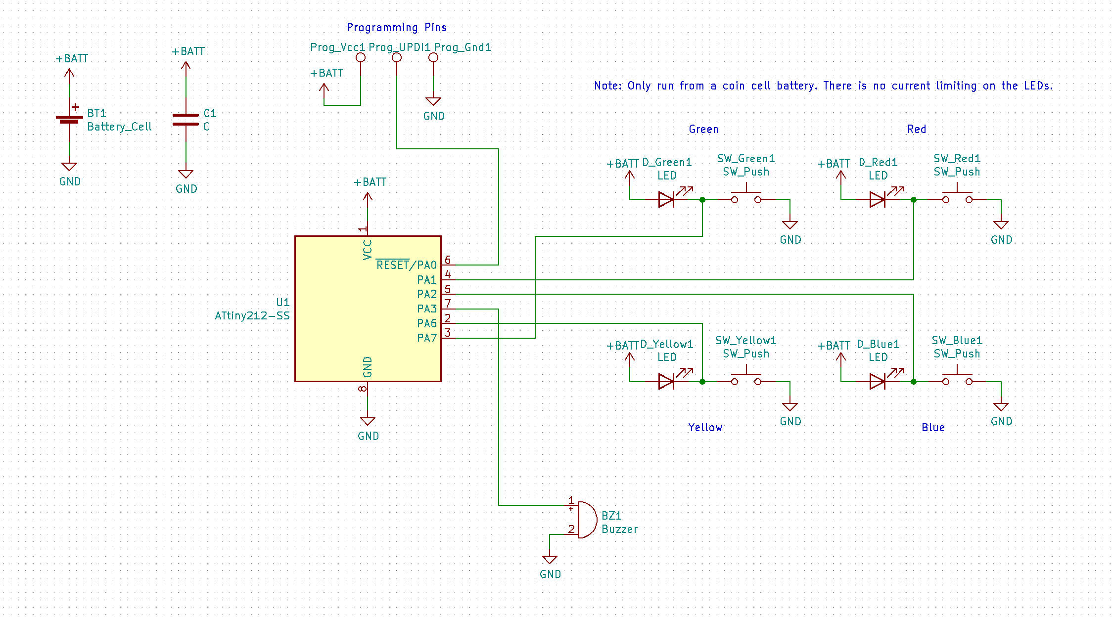
To save on microcontroller pins, the output LED and the input tactile switches share the same pin. The internal pull-ups were used for these input pins and debouncing was done in software so that addition components were not needed on the board. This allows the use of the small 8-pin ATtiny212 which only has 6 GPIO pins available.
Current limiting resistors on the LEDs are not included. The CR2032's voltage is close to the forward operating voltage of the LEDs and these coin cell batteries have a relatively high internal resistance. This keeps the LED's operating at a relatively safe current level. I say relatively as on a new battery the LEDs do run a bit over current. The green LED shows up as a yellow-green when the user is pressing the button indicating it's a little over driven.
I included a pad for a decoupling capacitor just in case but did not populate it. It seems like it is not needed for this application.
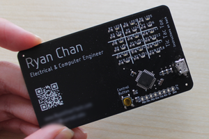
To keep the cards thin, I tried to 'reverse mount' all the components. Since the cards are 0.6mm thick, being inset in the card cuts that much off the height of each component. The LEDs were bought specifically as the reverse mount type and so I just followed the datasheet for mounting. For the ATtiny and Buzzer I basically hand measured the components for how I wanted them to sit in a PCB cutout and created new footprints with the package flipped over and the pads spread out by that new measured amount. Since KiCad doesn't handle cutouts in the pad editor, edge cutouts were added in the main view. I made sure to keep the pads for the buzzer a tight fit since it does not have leads on the package. This allowed me to use a solder bridge to attach the buzzer to the card.
The switches are tactile dome switches. I chose these as they were the thinnest switches I could find that also were easy for the player to click. Even though the datasheet for these switches says not to solder them, I wanted to give it a try anyway. I started by soldering a few tests pieces just at the very edge and this seemed to work OK. When I went to solder them on the actual PCB it didn't work out as well as in the tests. When soldered to the PCB they lost their 'clickiness' and didn't contact the center pads well. I wouldn't recommend trying to solder these type of no-solder dome switches and would recommend sticking to using tape.
I kept in mind to leave a large empty space in one corner to add my personal details to the card in case I actually handed any of these out like an actual business card.
Layout software view:

The KiCad project is available in the files section of this page.
Code:
Being that the ATtiny212 only has 2kb...
Read more »
 Ryan Chan
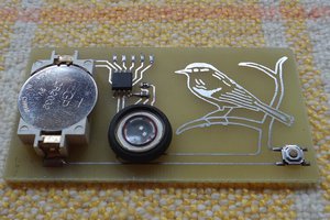
 brtnst
Thanks for sharing this work with us. I love to read and watch such content. I was also wondring for my own busness site (thenewsinsides.com) cards ideas and you solve it. Thanks