 loudaslife
The central component of this project is a PATA to SATA bridge IC. Unfortunately, there doesn't appear to be any suitable chip with (officially) publicly available documentation, so figuring out how to use them can be tricky.
The most common IC for this purpose is the JMicron JM20330. It's been used in other open source hardware projects, and can be purchased in small quantities relatively easily (though you won't find it on DigiKey or other reputable distributors.) You can even find a leaked old revision of its datasheet with some googling. However, the datasheet only gives limited information on the supporting components required. To fill in the gaps, I purchased what appears to be the official product evaluation board, the JM20330 EVB-002-3 "Host Bribge" Adapter.
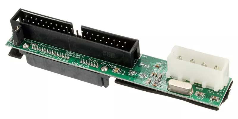
Considering their secrecy with datasheets, I don't think these are something JMicron authorized to be sold to the public. Rather, I suspect an unscrupulous manufacturer acquired the design files or manually recreated them (misspelling "Bridge" in the process). Regardless, this seemed like the closest thing to an official reference implementation that I could get. After a very barbaric dissection, I had decent pictures of the PCB traces and a spreadsheet of component values measured with my $15 "LCR-T4" component tester. Note that the lower photos are mirrored. I didn't photograph the inner layers, but they only seem to carry power and ground.
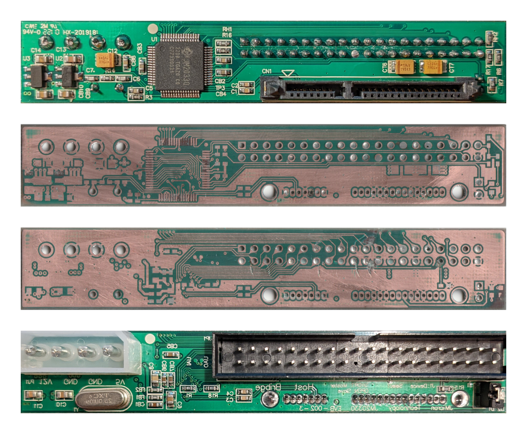
It was immediately apparent that many of the component values used in this sample probably weren't faithful to the original design. Some were replaced with cheaper ones, like 0 ohm links instead of ferrite beads. Others just didn't make sense, like having both 10uF tantalum and 10uF ceramic caps.
While I was researching this, I managed to acquire a copy of the official JMicron schematic for this board. It confirmed my suspicions, but also made all of my work so far pointless. Oh well.
| Reference designator(s) | As purchased from AliExpress | Official schematic value |
| C1-C4 | 10nF | 10nF |
| C5 | 100nF | 1uF |
| C6 | (too low for my tester to measure) | 5pF |
| C7 | (too low for my tester to measure) | 33pF |
| C8-C11, C13-C14 | 10uF | 10uF/10V |
| C12, CT6-CT7 | 10uF tantalum | 22uF/16V tantalum |
| CB1-CB8 | 100nF | 100nF |
| CB9-CB10 | 10uF | 100nF |
| FB1-FB2 | 0 ohm link | 100-450 ohm at 100MHz |
| R1 | 10K | 12K 1% |
| R3 | 10K | 47K |
| R6 | 300 | 330 |
| R7 | 1K | 1K |
| R14 | 10M | 1M |
| R15 | 10K | NC or 0 |
| R16 | 10K | 100 or NC |
| R17 | 300 | 100 |
| R18 | 10K | 1K |
| RH1 | 0 ohm link | 10K |
| RH2 | 10K | 10K |
| Y1 | 25MHz | 25MHz |
| U1 | JM20330 | JM20330 |
| U2 | 6206A SHC/1.8 | APL5508-1V8 |
| U3 | 6206A H221HD/33 | APL5508-3V3 |
| D1-D2 | LED | LED |
I forgot to test the knockoff board before tearing it apart, so there's no guarantee that the values it used actually work. Other than the values, though, my reverse-engineered schematic matched the official one exactly, so the PCB itself appears to be a faithful duplicate. I updated my schematic with the values used in the official one, and I've added the .kicad_sch file to the project files for whoever wants it. I used a schematic from the S6SSD project as a starting point and general reference, so credit to Wenting Zhang.

Discussions
Become a Hackaday.io Member
Create an account to leave a comment. Already have an account? Log In.