 Ted Yapo
So, what the heck, I'll look at timing before slapping something together. Here's a simplified schematic of the guts of the VGA framebuffer (it ignores the reset and connections between the two '4040's required to generate 19 bits of address). The dot clock is 25.175 MHz, for a period of about 39.7 ns.
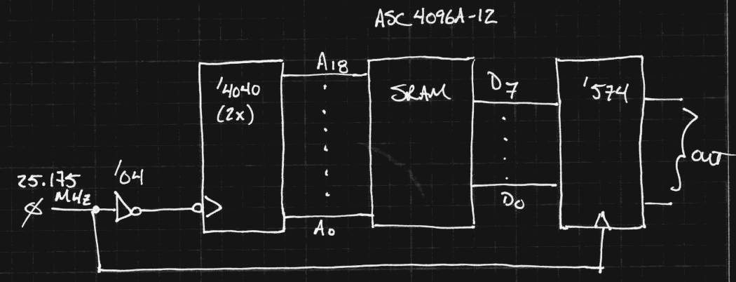
Looks simple, right? I started with 74HC logic - the 74HC4040 has a typical count frequency of 90 MHz, which sounds plenty fast. In the schematic above, the '4040 counters increment the address on the rising edge of the clock, while the '574 d-flop captures the data from the last address before it changes. I'm going to ignore those timing calculations for the moment (next log) because there's an even bigger problem here - it takes too long for the address to settle. The AS7C4096A-12 SRAM has a 12 ns access time, so the addess has to be stable within about 39-12 = 27 ns to work (ignoring setup time for the output register).
In the 74HC4040 datasheet, it specifies a tpd from CP to Q0 of 14 ns (typ at 5V). I'm using typical values for the moment; if it doesn't work there, it's not going to work worst-case, either. It further specifies the tpd from Qn to Qn+1 as 8 ns. Since it's a ripple counter, Q0 flips, then Q1, then Q2, etc, so we have to add all the delays so see how long it takes for the address to settle to the next value. When all of the bits have to change state, it takes 14 + 11 * 8 = 102 ns for the output lines to show the correct address - that's way too long, since we have less than 40ns to get the next byte of data out. This also ignores the fact that two 74HC4040s need to be chained to generate the 19-bit address: in that case, we're looking at 14 + 11*8 + 14 + 6*8 = 164 ns for all the address bits to settle.
VHC to the rescue?
I haven't used VHC logic before, but keep seeing it around. Surely the 74VHC4040, with its 210 Mhz typical max clock frequency will do the job! Let's run the numbers, using a 15pF load : tpd (CP to Q0) = 4.8 ns, and tpd (Qn to Qn+1) = 1.6ns. So, with two of them connected to generate 19 bits of address, the tpd from the clock edge to the MSB settling is: 4.8 + 11*1.6 + 4.8 + 6*1.6 = 36.8 ns. Add in the 12 ns access time of the SRAM, and we're definitely over budget.
It's a shame, because the '4040 packs 12-bits into a single package. I have to go take them out of my shopping cart now :-)
What about the '393 counters?
The 74VHC393 is another candidate - it has twin 4-bit counters in a package, so three ICs would be necessary. I started with the VHC part this time :-) In this case, the propagation delays are specified for each of the four bits. For Qd (the fourth bit), the typical tpd is given as 8.5ns (assuming a 15pF load), and the Qc tpd is 7.7 ns (the third bit). With five counters chained, the typical time to get the 19th bit settled is 4*8.5 + 7.7 = 41.7 ns. Nope.
Synchronous Counters
Synchronous counters use extra logic to form the next state from the previous one directly, without waiting for clocks to ripple through, so the outputs settle faster. The disadvantage is that they seem to only be available in 4-bits/package. Now, I need 5 ICs to make the counter - if it's even fast enough. The 74VHC163 claims 185 MHz at 5V - maybe that will work. Interestingly, it also has a synchronous clear, and connections for synchronous expansion between counters with lookahead carry outputs. If I'm reading the datasheet correctly, the maximum delay from clock edge to valid outputs is 10.1 ns (at 5V) - even expanded to 20 bits. This would work - with the 12ns SRAM access time, still way under the 40ns cycle time.
How about the 74HC163? 74HC parts aren't specified at 5V for some strange reason, but at 6V, the tpd (max) is 35 ns, and at 4.5V it's 41 ns. Doesn't look promising - although the typical 21ns (6V) or 25ns (4.5V) sound workable.
If I were going to build a bunch of these, I'd try harder to get the 74HC163 to work. Since I'm only building one, and on a deadline, I'll spring for the more expensive 74VHC163s. I need 5 of them, which sucks.
The clock input on the '163 works on the positive edge, so the schematic above changes a bit, but at least the addresses seem OK. Next step - the rest of the logic and timing calculations.
Did I miss something on the ripple counters? Maybe I'm doing this wrong?
This is where a little CPLD would be nice - but that would count against my 1kB ;-)
PIC Address Generation?
What about using the fastest PIC available and bitbanging the address lines? The fastest ones I can find are 64MHz, or 16 MIPS. Even if you could output a new address every cycle, that's still only about half of the 25.175 MHz clock required. Maybe a fast external counter for the lowest 4 (or 8) bits, and the PIC generates the upper ones? Synchronization is an issue, but it's worth thinking about - maybe if the PIC runs from the external 25.175 MHz clock, and synchronizes itself with the external low-bit counter(s)? This could be interesting.
Discussions
Become a Hackaday.io Member
Create an account to leave a comment. Already have an account? Log In.
All these numbers involving multiples of propagation-delays are making me question even further how I got the ol' LCD controller running. Musta been a bunch of pixie-dust in there, or a poor memory of 18 years ago.
Interesting discovery upon looking back... the HC series is actually slower than the older TTL(!?)... The 74163 and 74LS163 look to be about 75% faster (guess I lucked-out my parts-bin was mostly not CMOS).
Great explanations of the counter design-process/trade-offs up in here.
Are you sure? yes | no
That's the thing about the datasheet values and worst-case design - if you just build it, you might end up with best-case parts or be at a near-ideal temperature, or whatever, and it might just work once, or twice, or even 95% of the time. Until it doesn't.
I think I have some 74HC4040's around here somewhere - or at least a 74HC4020. I can hook one to the four-channel scope and have a look at the delays between the LSB and successive bits. I was surprised by this analysis, but there's a reason people make/use synchronous counters.
I think LSTTL is even faster than the 74xx parts - at less power.
So, I went to order 74VHC163s - OBSOLETE! 74AC163's are still around, though, and seem fast enough, so that's the plan.
Are you sure? yes | no
LOL ACs strike again! Don't forget that ground-bounce!
Are you sure? yes | no
Dammmmnnn ground bounces...
Are you sure? yes | no
I spent the afternoon re-working my ugly SOIC adapter board designs to reduce the ground-connection impedance and add on-board bypass caps. They're not completely general anymore, since now they assume standard corner pin supply connections, but they should be better for signal integrity.
Those bounces won't kill this project.
I hope.
Are you sure? yes | no
BTW you can use 25MHz for VGA dotclk as it is a bit cheaper than 25.175MHz. Monitors can handle some clock frequency variations.
If you got a large RAM chip, you could use 10 bits from one ripple counter for the column address. The row address can be updated from the horizontal sync. That should relax some timing as your MSB are no longer rely on the propagation from the lower bits.
1024 x 480 = 480kB, a 512kB should be enough.
One important thing is that you have to make sure that there are no video output outside of the 640 dots as modern monitors use the presence of video signals to determine the edge of display for adjusting screen sizes.
If you want to be sneaky, those extra unused RAM for the row can be used for Hsync/Vsync generation outside of display area.
Are you sure? yes | no
I saw the 25 MHz trick in your terminal project - good to know. I have a tube of 50 MHz cans around here that I could divide down, but since I have to order parts for this thing anyway, I might as well pick up the exact frequency for a few bucks. If I were making more than a one-off project, I think the 25 MHz idea might be the way to go.
Cycling back the hsync for a second counter is interesting. I'll have to give that one some thought.
Yeah, I had read about keeping video blanked outside of the active area. In the store-each-dot-period-as-a-byte plan, this is trivial - I have full and easy control of all the singals on on a per-dot basis.
Are you sure? yes | no
74HC163: that's what I use for the registers of #Discrete YASEP :-)
Are you sure? yes | no
I agree: all memory should be incrementable!
Are you sure? yes | no
In this case, it's not memory but registers. It still makes #YASEP Yet Another Small Embedded Processor a pretty efficient architecture, since it was designed to process data streams :-)
Are you sure? yes | no
Maybe you can use the PIC and run the RAM at half or 1/4 the speed for a lower resolution display ?
OR : use 2 or 4 SRAMs, and MUX4 the output to select the current pixel (this brings memories from the 80's style to build home 8-bitters)
Are you sure? yes | no
I think either one would definitely work, and it would make an interesting project, but I've somehow got it into my head that I need actual 640x480 :-)
Muxing more RAMs could work, too, but I want to minimize parts count.
I'm already bummed about the 64-color thing...but resisting the urge for widen the RAM.
Are you sure? yes | no
I have RAMDACs in stock, if you want to save parts and use a palette for a virtual 18bpp display :-)
Are you sure? yes | no
"If I were going to going to" ?
Are you sure? yes | no
Thanks, I get interrupted a million times a day; sometimes it shows :-)
Are you sure? yes | no
"You're my NMI !!!" :-D
Are you sure? yes | no