 Ted Yapo
It turns out that the 24-bit floating point implemented in the XC8 compiler requires a few tweaks of the ray-tracing code. My goal is to re-write this all in 16 (or 24) bit fixed point, anyway, but the code I had ready used floats. Here's the problem:
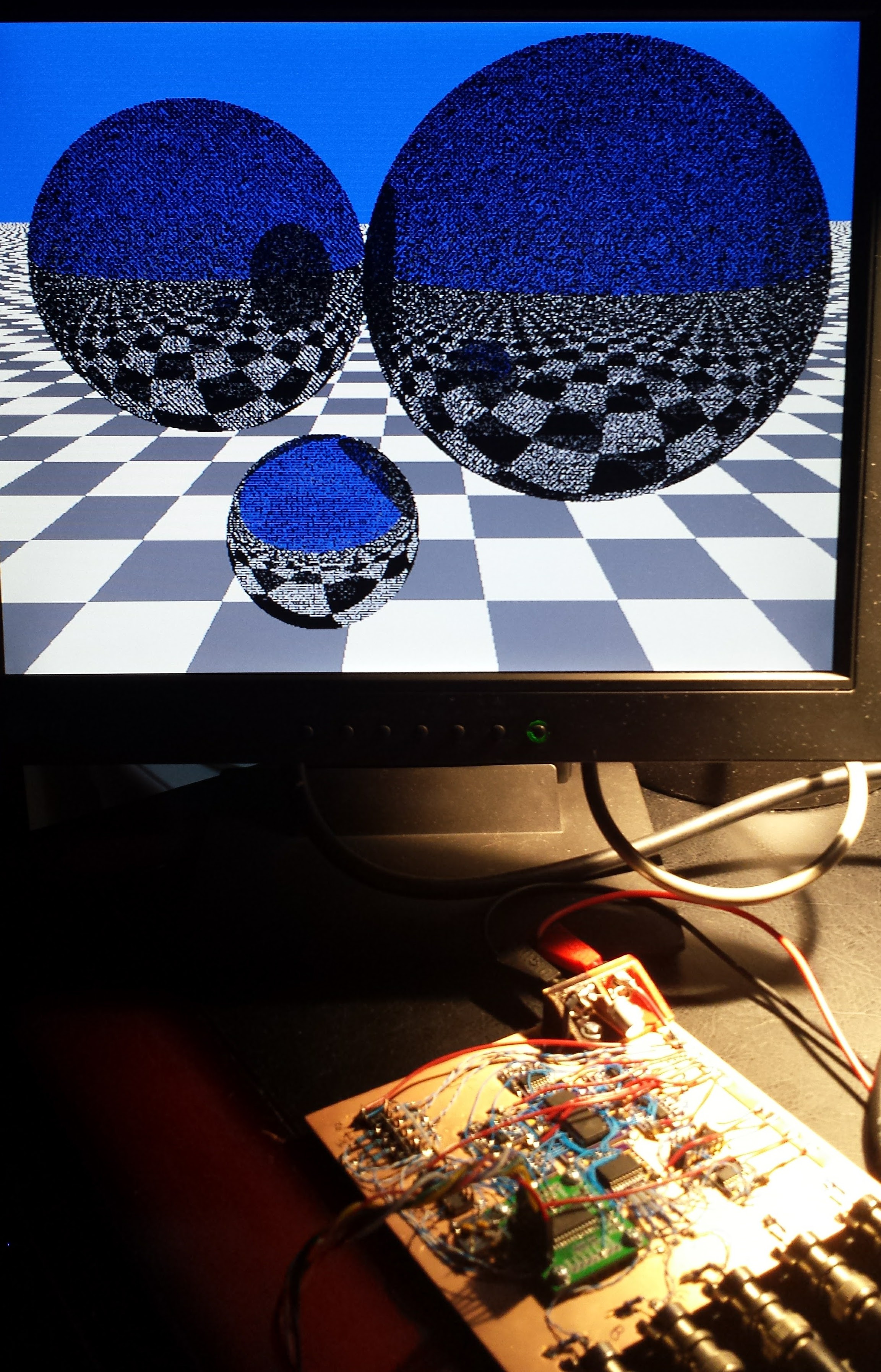
The noise on the spheres is caused when rays bounce off, then are found intersect the sphere again immediately. This happens because if the origin of the reflected ray is right on the surface of the sphere, it's ambiguous which side the ray originates on - the dropout points above are where the origin of the reflected ray were found to be inside the sphere, so the ray got trapped in there instead of bouncing off normally. The classic solution to this classic problem is to add a small offset (epsilon) to the reflected ray origin to ensure the reflected ray remains outside - and the required magnitude of this offset depends on the numerical precision used.
I tested this code on my linux box with IEEE 32-bit floating point, where my chosen epsilon was sufficient. Porting the code to the PIC with 24-bit floats looks like it requires a few tweaks. I changed one line to bump epsilon:
      // reflect from sphere
      float eps = 0.1;
and I have it running again.
CONTEST DISCLAIMER: this code is 8.3kB in size.
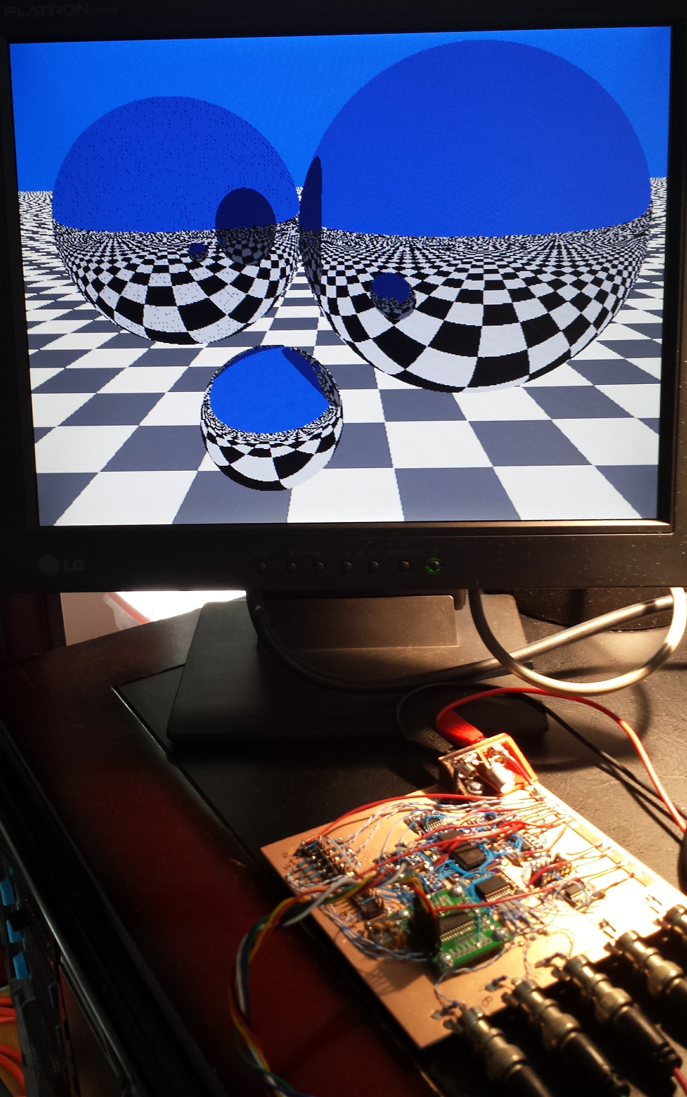
Second Try - Slightly Less Fail
My epsilon is still too large - dropouts on the left-hand sphere only now. It's running again...
Discussions
Become a Hackaday.io Member
Create an account to leave a comment. Already have an account? Log In.
haha, I like the first one better, it looks more like what one would expect this uC to be capable. The other looks too pristine, like "how do I know he didn't just plug a PC into the display's second input?" ;)
Are you sure? yes | no
I forget where I heard it - maybe some architecture student told me - anyway, when you make a model of a space for a project, you intentionally put in a door that won't open fully or some other flaw that the professor is sure to find. For some reason, this raises your grade - maybe it makes you less of a threat or something.
That's the problem with simple ray-tracers: the super-realism is distracting. It took a long time to figure out how to make them look as crappy as real everyday scenes.
Are you sure? yes | no
Interesting anecdote :-)
Anyway, the realism is not an issue, considering the run time...
Are you sure? yes | no
Interesting, indeed. and probably wise words. Though, adding a flawed door to a project isn't something I'd have to do intentionally ;)
Are you sure? yes | no
@esot.eric I think the magic only happens if you add another flaw on top of the natural ones - those you somehow always get dinged for. It's just one of those things :-)
Are you sure? yes | no
Looks amazing! How long does it take to calculate full frame?
Are you sure? yes | no
Thanks :-)
I didn't time it exactly - I have an idea to run an external elapsed timer with zero added instructions, but haven't done it yet. I estimated 8 originally, but I think it's between 2 and 3 hours - I ran one today, did a bunch of other things, and when I returned, it was done. I used to write things like this in compiled BASIC in the early 1990s (but I had an 8087 floating point co-processor), and it seems about the same.
(check out the next log for the corrected image by the way)
I'm going to use an AA-battery powered analog clock to time the thing - I'll make a power supply for the clock with a resistor and a few 1N4148s as a simple 1.5V shunt regulator, and power the "regulator" from one of the PIC I/O pins on a port I'm already using. I'll just add a "1" bit in one of the control words I'm already outputting.
To time the run, you manually reset the clock to 12:00. It continues to run until the PIC drops the I/O line when it turns on the VGA display. The clock stops at the elapsed time.
Are you sure? yes | no
2 hours? not bad
Are you sure? yes | no
It looks like you create cool code that I can reuse to test my CPUs ? :-D
Are you sure? yes | no
Thanks, Yann. It's open-source, you can use it however you like. But, it's simple one-off code that's probably not useful for anything other than demos on simple processors. I ignored numerical details.
But, you're not seriously going to target a C-compiler to your relay CPU are you? :-)
Are you sure? yes | no
why not ?
C or a custom pseudolanguage will do, as long as the algorithm maps well.
The point is that I'll use the same architecture for relay, Ge and Si versions (I'm now considering creating the Si project page). The Ge and Si version might run fast enough to do "meaningful" stuff (a few MHz ? more ?). I'll cheat for the RAM (using standard fast SRAM) but then it will be too fast to run the game of life :-P
Generating pictures (RGB or greyscale) OTOH might provide a significant enough challenge ;-)
Are you sure? yes | no
@Yann Guidon / YGDES Why not, indeed. I wonder if emulating the simplest architecture that already supports a C-compiler might be the easiest route? It's not quite the same thing, but would probably be the fastest way there.
I had a job programming dedicated imaging DSPs at one point. They used an algebraic assembler language that was a proper subset of C. So you'd see things like this:
while (count--) {
...
y += a * b + c;
...
}
Each line turned into exactly one machine instruction, so there were a limited number of valid C statements you could use. But, since it was also a valid C-program, you could just compile, run, and debug it on your desktop before moving it to the target device. Very convenient.
Oh, and I think the relay CPU could easily drive this VGA hardware. There's no need for speed - the PIC is currently taking a few hours to fill the SRAM. It could be weeks or months instead, as long as you don't lose power :-)
Are you sure? yes | no
The Analog Devices DSP have an algebraic assembler, I remember my ADSP12xx/x fanboy years :-)
Are you sure? yes | no
@Yann Guidon / YGDES Yes, I know the SHARC a little. I had one and a half job offers with that company on different occasions, but for various reasons, I didn't end up working there.
Are you sure? yes | no
I loved the SHARC so much, its manual was one of my favorite books during university :-)
For the relay computer, there is a direct memory-mapped flip-dot array (see #Dot flippers ) and it's pointless to have a VGA display (640×480 would take ages just for filling, even at 20 IPS)
The Ge and Si versions however could use a "dumb VGA" like your system. This is interesting because that would set the general clock to 25MHz (or a co-multiple) to avoid cross-domain clocking issues. If a CPU access is detected during a video line, the last pixel could be repeated (or I can use dual-banking).
Given the average 1:50 speed ratio between an individual transistor and the system speed, I'll need 1.2GHz transistors for a 25MHz CPU :-D The Ge are "around 500MHz" so maybe I can reach 12.5MHz ? The Si are BC549C @250MHz so I hope to reach a few MHz... These transistors are cheaper so I might implement some sort of pipeline.
But overall, yes, the 25MHz goal seems to be an interesting challenge since the original question was "how fast can Ge compute". 24.576MHz is also a good idea for direct division to get serial communications.
Additionally, I consider adding a MMIO bus to access a WZ5300 for networking purpose and I/Os :-)
That thing is going to be crazy...
Are you sure? yes | no
@Yann Guidon / YGDES The 1:50 ratio is very interesting. What is it based on?
Are you sure? yes | no
https://www.ecse.rpi.edu/frisc/reports/spring95/s95.html
(there are several fascinating reports of a 1GHz RISC IC in AsGa and SiGe there : https://www.ecse.rpi.edu/frisc/theses/PhilhowerThesis/ , https://www.ecse.rpi.edu/frisc/theses/SteidlThesis/phdthesis.html etc. )
of course my version will have considerably more capacitances and inductances so the ration might be higher, and I didn't take pipelining into account.
Are you sure? yes | no
@Yann Guidon / YGDES Thanks! Interesting links; I'll have to read them more thoroughly when I get the chance. It's funny that stuff came out of RPI. I spent (too) many years there as a student - I still live about 30 minutes away :-)
Are you sure? yes | no