 Silícios Lab
Introduction
Does every project with electronic logic need a Microcontroller or Arduino to be developed? Today, many people use Microcontrollers to solve a problem.
Is there an error in this? None! But the project may have increased costs and make it difficult to sell to end consumers. It is for this reason that we need to look for simple and viable solutions.
In the project presented in this article we will present this to you. In it we will show you how to implement a simple solution and investing little money with electronic components.

In this PCBWay article you will learn how to develop a sign to signal the change of direction of cyclists in traffic.
Every year, several cyclists are involved in traffic accidents due to other people's mistakes or because they do not use adequate signage. This ends up causing many deaths and leaving people unable to get around.
To avoid this problem, PCBWay supported the development of a lane change signal for cyclists. In addition to providing security, the project is open and you can use it to sell to other cyclists.
It uses few electronic components and is easy to assemble. Now, let's understand the complete structure of the electronic circuit.
Electronic Circuit of the Turn Signal for Cyclists
The figure below shows the electronic circuit of the project.
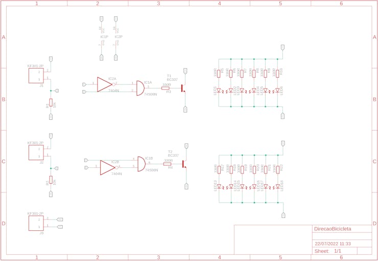
How does the electronic circuit work?
The electronic circuit is formed by a group of LEDs that will be used to signal that a cyclist will turn left or right. This will be done through the use of two buttons.
Each button will be connected to the handlebars of the bicycle and will be connected to the circuit on the board through wires.
The signal from each button is sent to the logic circuit input of the electronic board.
This circuit was developed using combinational logic. Through logic gates it was possible to implement the complete solution for this circuit.
What logic was implemented?
The combinational circuit is formed by two inputs, which are the left button and the right button.
Combinational logic works as follows:
- Turn off all LEDs when buttons are not pressed,
- Turn on the left LEDs when the left button is pressed,
- Turn on the right LEDs when the right button is pressed, and
- Turn off all LEDs when both buttons are pressed.
From this logic, a combinational table was created to relate the digital inputs with their respective digital outputs. See the table below.
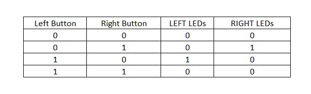
This table presents the combinations of inputs and their respective digital outputs. From this table, a Boolean logic expression was developed and we set up the logic circuit below.
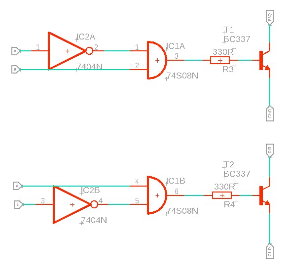
At the output of each circuit, transistors were placed to switch the set of 6 LEDs to signal left and right.
The group of LEDs is shown in the figure below.

Each group of LEDs was connected to the collector terminal of each transistor. This allowed to drive all the LEDs through a single transistor.
Finally, we insert 3 screw connectors into the electronic circuit.
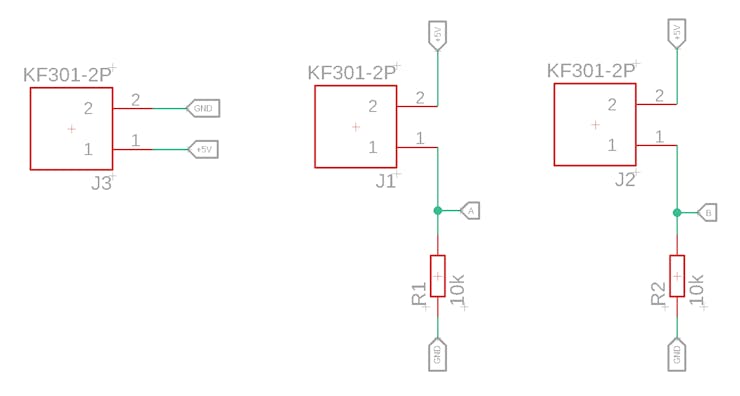
We have a connector for powering the electronic project with a +5V battery. The other 2 connectors will be used to connect the buttons. A 10kR pull-down resistor was inserted for each button.
Finally, we finalized the electronic schematic design and developed the layout of the printed circuit board. See the result in the figure below.
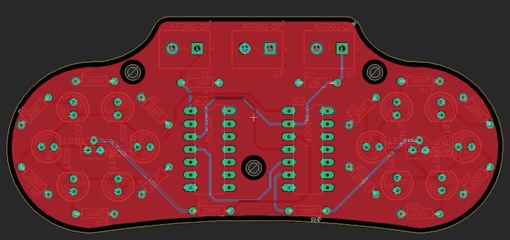
3 holes were inserted in the electronic board to facilitate the fixing of the board on the bicycle frame or in another place desired by the cyclist.
The following is the full 3D view of the board in Fusion 360 software.
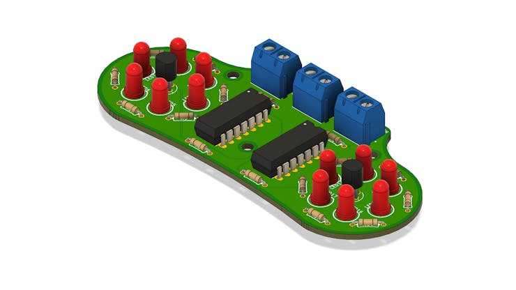
This electronic board is easy to assemble and you can find the components in any store in your city, as THT electronic components were used and this facilitates the board assembling process for any user who wants to use it.
 Kelly Heaton
 RachelAnne
Using a quad NOR (7402) you can get away with a single chip. Use two as inverters by linking both inputs together, then use that as inverter on the other input as in your design, since (A & !B) == !(!A | B)