0%
0%
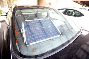
Mini Solar System
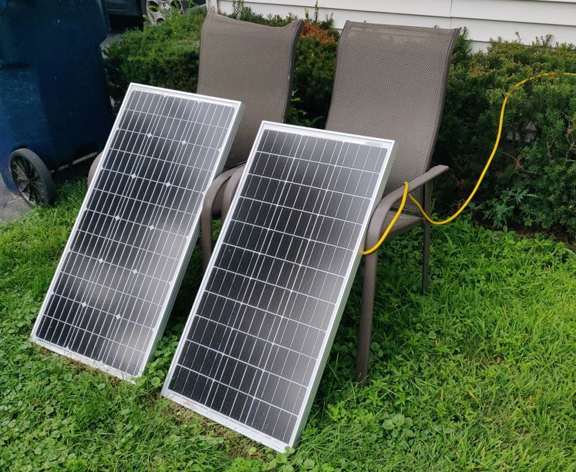
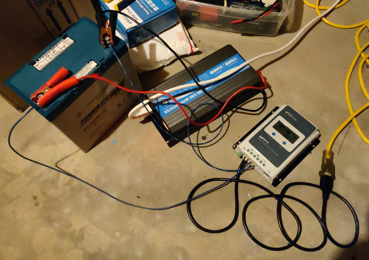
A small off grid solar system that can provide long term emergency power for household appliances
 Drew Pilcher
Become a Hackaday.io member
Already have an account? Log in.
Just one more thing
To make the experience fit your profile, pick a username and tell us what interests you.
Pick an awesome username
hackaday.io/
Your profile's URL: hackaday.io/username. Max 25 alphanumeric characters.
Pick a few interests
Projects that share your interests
People that share your interests


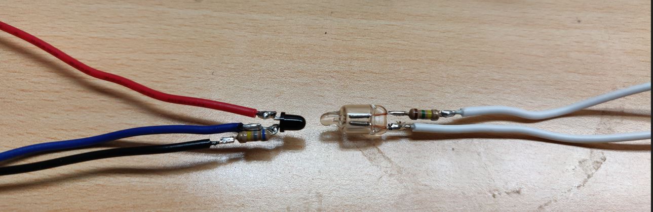
 Then a layer of heatshrink with internal adhesive (to add some rigidity):
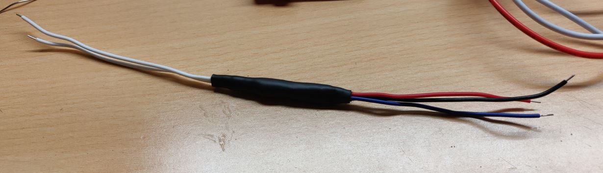

 lion mclionhead
 Bryan Williams
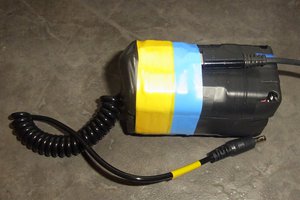
 andyhull
Hi Drew.
Here: https://hackaday.io/project/193235-mini-solar-with-ac-backup
I just published a very similar project .
I appreciated very much your homemade battery but I preferred the more confortable way to buy one 😀. On the contrary I concentrated my efforts to a monitoring system to view and chart the working parameters of this mini plant.