 Sagar 001
There are many methods to measure the DC current. Hall effect sensors and dedicated hall effect current measuring ICs are available to measure Current precisely. But in this tutorial, we are going to cover very basic method to measure current using shunt resistance in the circuit.
We will also make our own current sensor and turn it into fully functional PCB. You can refer to the previous video in which we made a shunt which drops 10milli-volts per ampere. From there you can clear the concept of shunt resistor.

I am using JLCPCB PCB prototyping service for a long time, I made many projects using SMT service also. JLCPCB also offers a lot more services including SMT Assembly, PCB prototyping, Stencil, 3-D printing and PCBA double side. Sign-up now to get free PCB coupons up to $54. And use them at the time of checkout for a great discount.
Shunt resistor:
A small resistance(known) in order of 0.01 to 0.1 ohm, which can be connected in series with the load so that voltage drop across it can tell the current flowing through the circuit. See this article "how to make a shunt resistor" this will also clear calculations.
The current in the circuit is given by the ohms law: V=IR
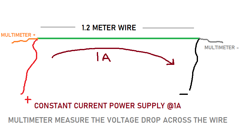
If Shunt resistance of 0.01ohm and Voltage drop across it is 0.01volt then:
Current = V/R = 1Ampere
Try to make the shunt as small as possible and if you want to reduce the calculation then try to control the resistance in integral number. Because I am using 10milli-ohm resistor which drops 10mV when 1 ampere is flowing through it.
Amplification:
Because 10milli volt per ampere is very low, I want to measure a maximum of 5ampere. In this case only 50milli-volt fulfill the needs. It is easy for us to calculate but microcontrollers would not give any output change on this small voltage change.
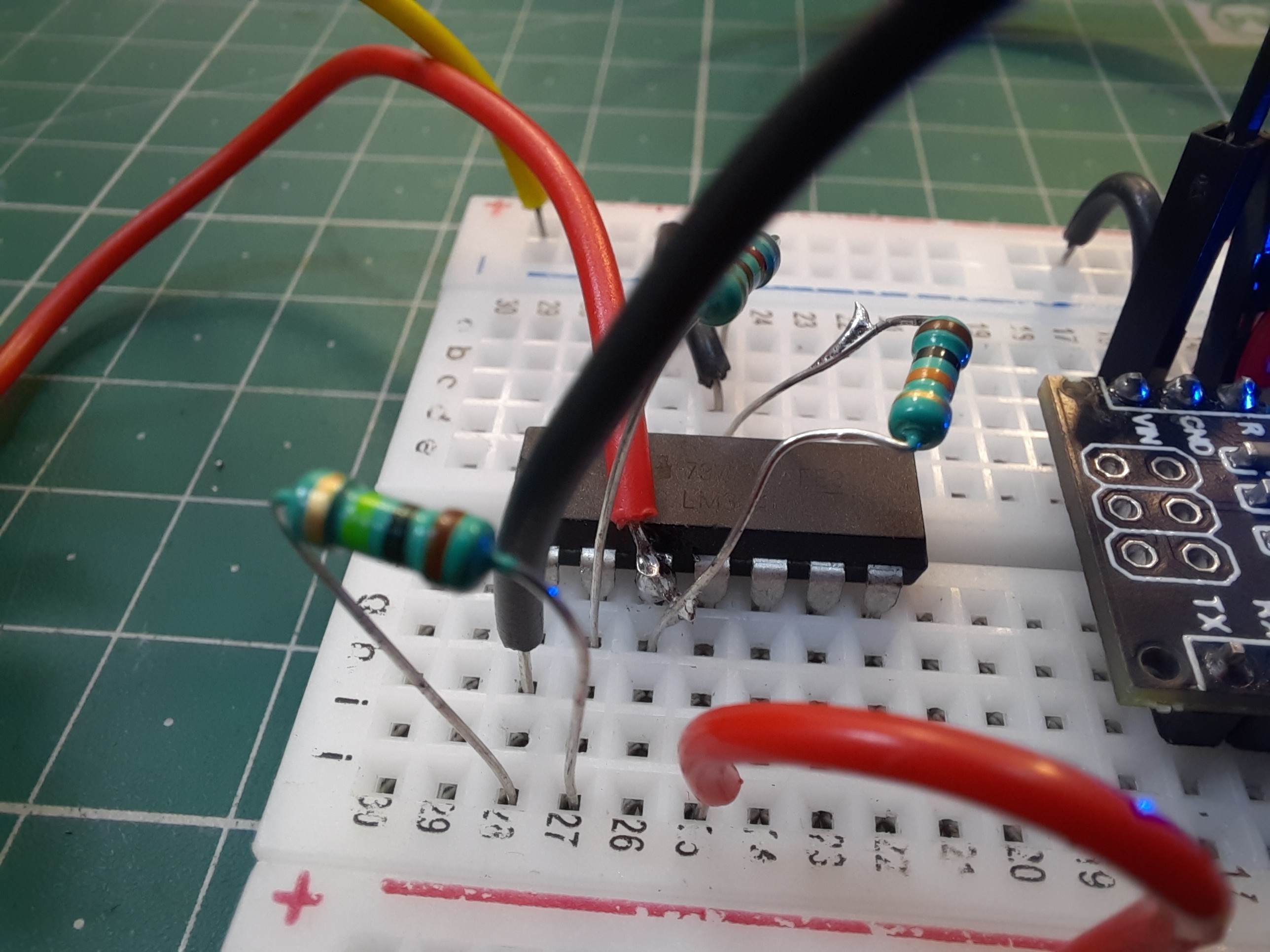
So, we need a proper amplifier to amplify the signal, so that we can display values using Arduino microcontroller. We have to go with instrumentation amplifier for better precision and accuracy but operational amplifier may do the fine job. Here, I will use LM358 operational amplifier in non-inverting configuration mode. The gain of amplifier is multiplied by the signal and then give an output.
Keep in mind, Arduino ADC can work at a maximum of 5volt, we also have to measure 5 amperes at max. So, we can increase the amplification factor 1v per ampere. Which not only gives the better precision but also, we can measure the current directly using any voltmeter.
Amplification factor calculations:
Initially we are getting 10mV for 1ampere, to amplify the voltage to 1 volt we need a 100x gain. The non-inverting configuration gain is given by 1+Rf/Rin.
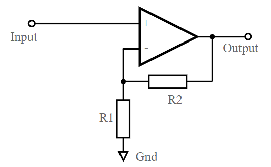
R2= 99k, R1= 1k gives the gain of 100. But here we are using 100k resistor with 1k resistor which is the general value and gives a gain of 101 == 100. Which is almost equal, in the Arduino code we can do some changes to get the better accuracy. Keep the reference level in mind while working with operational amplifiers.
Why 1volt for 1ampere:
We are amplifying 1volt to 1ampere which gives a full-scale resolution to Arduino ADC also we can measure the current using any voltmeter. But here we are using 5v supply with the IC, which restrict a maximum gain to the supply voltage.
In case we have to measure 10Ampere or more then use a power supply greater than 10volt and then with the voltmeter get the output directly form the output pin of Op-amp. Or you can push the amplification factor down to get an output of 10amps @5volt i.e.- 0.5volt per amperes.
Components required:
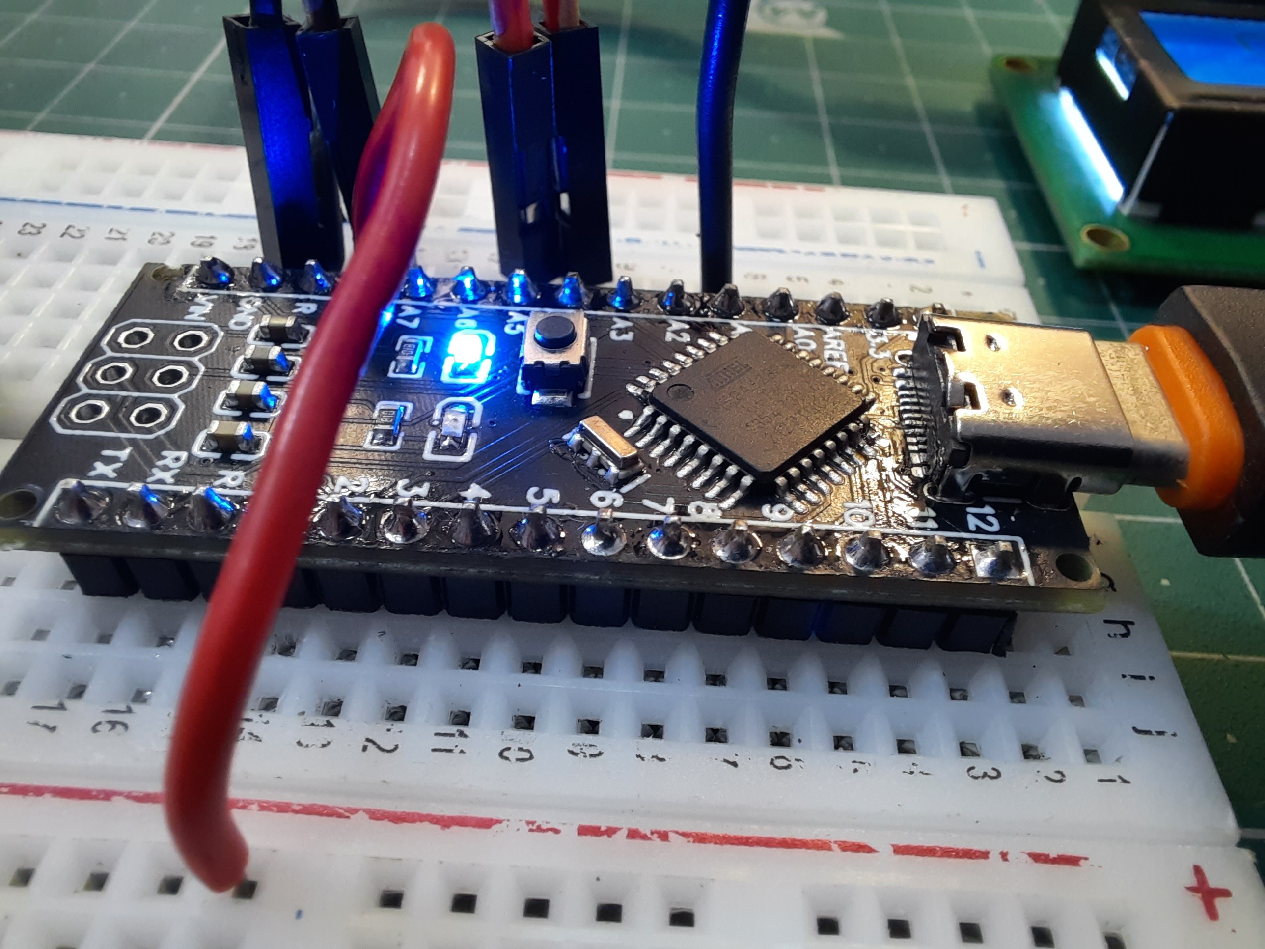
1) Arduino Nano
2) LM358
3) 10mV/A shunt resistor
4) 9-volt battery
5) 100k, 10k, 1k resistor.
6) I2C LCD 16*2
7) Connecting wires
8) Power supply
9) Load resistance (DC-motor)
10) Custom PCB(JLCPCB)
Circuit diagram:
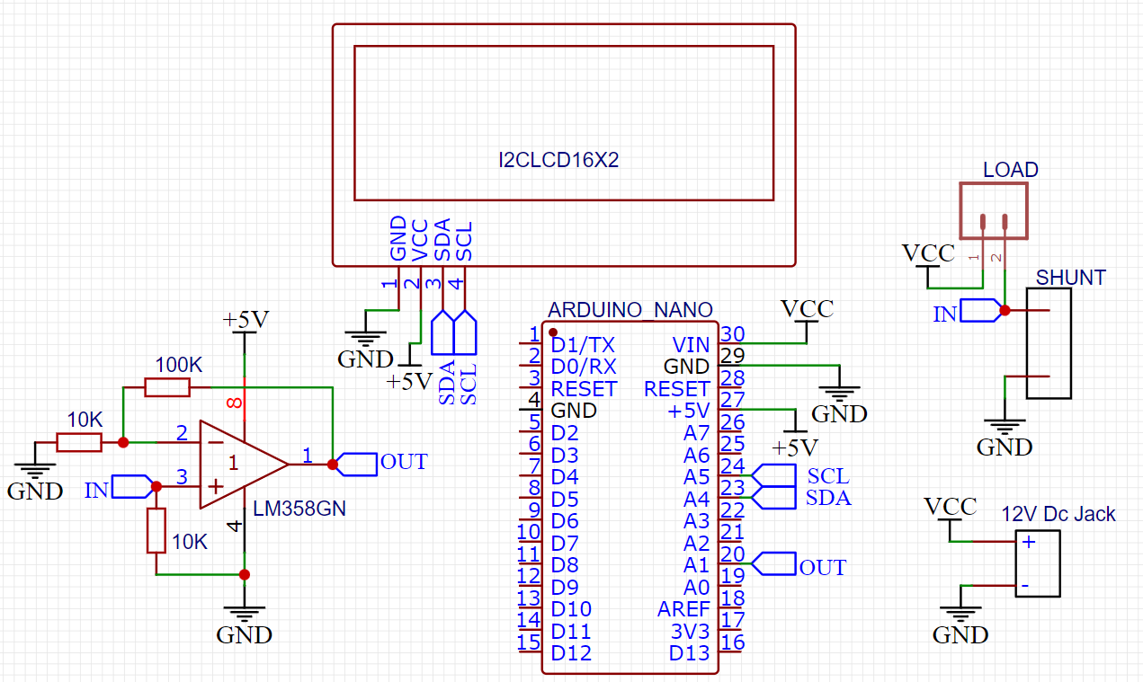
Pin 3 of the IC is the input which is also pulled down with 10k resistor to match the reference level. 100k, 1k resistor to proving a gain of 100 to the system, the output of op-amp is given to the analog input of Arduino to measure the voltage in terms of current and then to display the output.
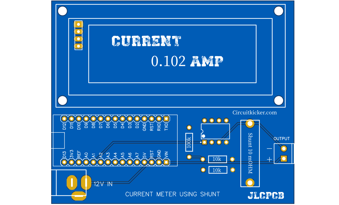
PCB files:
I had given 2 PCB files one for the dedicated ampere meter and other one is for current sensor. So, either you can measure using Arduino and I2C display with dedicated current meter or can measure using voltmeter from current sensor.
Ampere meter:
Current sensor:
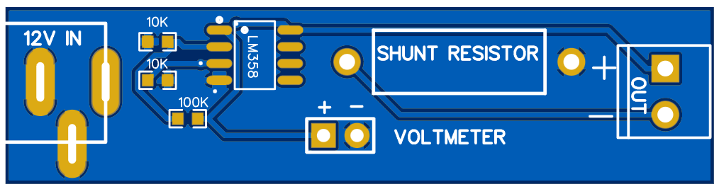
The current meter configuration can be changed as per given resistance on the back silk layer of the PCB. If you want to make the same files as mine then get them from here. This project is sponsored by JLCPCB, 5 pcs 2layer PCB in just $2. Sign-up now using this link and get new user coupons of $54.
Arduino Code:
Try to install the latest version of the used libraries directly from Arduino IDE, manage libraries under tool menu.
// current meter
// We has 10mv per amp shunt amplified to 500mv per amp by OP-amp non-inverting confg. Rf=49, Rin= 1k
// Now 0.5v= 1A,so we changed the output as current/2, which gives 0.5v as 0.5amp
// Resolution

#include <Wire.h>
#include <LiquidCrystal_I2C.h>
int analogPin=1;
float current = 0;

LiquidCrystal_I2C lcd(0x27,16,2);  // set the LCD address to 0x27 for a 16 chars and 2 line display

void setup()
{
  lcd.init();                      // initialize the lcd
  lcd.init();
  // Print a message to the LCD.
  lcd.backlight();

}
void loop()
{
  float c= analogRead(analogPin);
  current= c/1023*5.0;
  if (current<0.5)
  {
   lcd.setCursor(1,0);
   lcd.print("Current=");
   lcd.setCursor(4,1);
   lcd.print(current*1.1);
  delay(500);
}
else{
      lcd.setCursor(1,0);
   lcd.print("Current=");
   lcd.setCursor(4,1);
   lcd.print(current);
  delay(500);
}
}
Working:
In the code at low ampere the output is not stable that why I introduce the IF statement below 0.5ampere and then you can change the output factor to calibrate your sensor.
Mine one is working fine after calibration and now I can use this as a display or modify the code to make power meter. Stay tuned for the other version of the current meters. I take electro noobs video of current meter as reference but there are some mistakes. After realizing and wasting my time with that one I am representing this in front of you. So, that you may get a basic idea to current measurement.