 Christian Lo
Features
- Low Profile
- Keyboard is around 16.5mm thick, keys and keycaps included
- 1.8" LCD Screen
- Ample real estate for animations, UI, games(?), etc.
- Uses the Raspberry Pi Pico
- 2MB of flash storage
- Lots of room for programming with MicroPython, or room for graphics and code
- Parts readily available
- Only SMD parts required are diodes and kailh choc hotswap sockets
- Uses Rust firmware
- This alone gets people excited??
- Uses Keyberon as the firmware base, allowing for a "modular" firmware that can easily be built upon
- More details can be found in DESIGN.md in Github
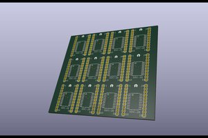
Big thank you to PCBWay for sponsoring the PCB for this project. I'm happy with their service, and I think the quality of their boards are superb. I'm very happy with both the silkscreen and solder mask quality, and recommend them to anyone who wants to print their own PCB.


 Ken Yap
 tshen2
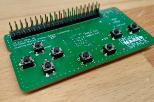
 micl
micl
 Dylan Brophy
what You think about this? https://klawiatura.wordpress.com/