 Jamie Searle
Caliber Profile
The caliber hanger profile is a rectangle, with one rounded edge. Sounds simple right? All I need to do is take some measurements.
Unfortunately, not all trucks are built the same. Since I don't have access to the technical drawings for the caliber trucks, I cannot tell the tolerances on the hanger dimensions so I will take reference from a few sources.
Also, the profile appears to be thicker towards the centre than at each end, so I need to take this into account too.
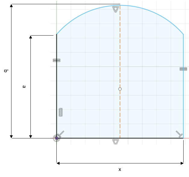
| Source | a (mm) | b (mm) | x (mm) |
| Front truck left | 14.0 | 18.8 | 18.0 |
| Front truck right | 14.0 | 19.2 | 18.0 |
| Rear truck left | 13.8 | 19.0 | 18.0 |
| Rear truck right | 14.3 | 19.3 | 18.2 |
| ESK8 forum post | 16.6 | 20.7 | 18.2 |
| GrabCAD | 15.2 | 19.8 | 17.8 |
The inconsistencies in my measurements may be explained not just by manufacturing variations, but also from measuring at different points along the hanger.
I have assumed that Caliber II trucks have the same profile as Caliber III trucks, but what's interesting is that the two Caliber II sources have a value of a which is 1.4 - 2.8 mm longer. The width of the profile, i.e. x, seems to be consistent at around 18 mm, and the height, b, varies within a 1.9 mm range.
I could validate my results by asking other caliber truck owners to measure their hanger profiles, or even by contacting the manufacturers themselves to find out, however I'm impatient and this is just a hobby project so this should suffice.
I will proceed with the following nominal dimensions:
| a (mm) | b (mm) | x (mm) |
| 14.5 | 19.5 | 18 |
Any variation in these values will be accounted for in the design of the clamping mechanism.
Rev 1
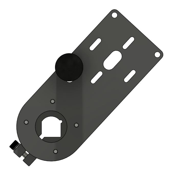
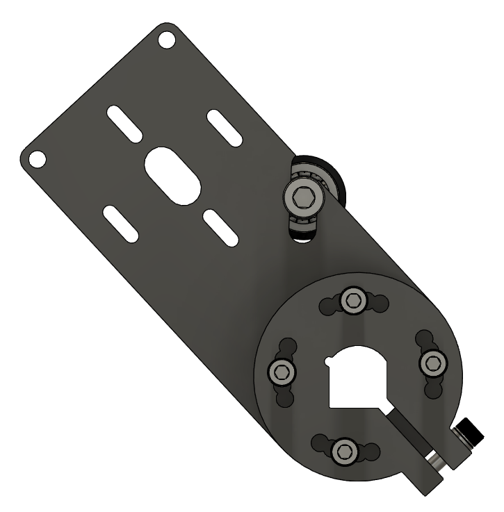
Truth be told, I'm incredibly proud of this. After a few hours in Fusion 360 I have what feels like a no-compromise design. however, before my head stops fitting through the door, I need to do some physical testing and receive feedback from the ESK8 community to validate it. As with any product, I'm sure there will be plenty of revisions to come.
I will not provide a detailed explanation of every design choice, dimension and fastener length, however here are some of the main considerations.
Firstly, you may notice that the clamping mechanism is not a direct copy of the Boardnamics motor mount. This is to reduce the number of parts, therefore theoretically reducing the number of things that can go wrong and hopefully providing a more stable solution. My only concern with this is that the displacement of the adjustable holes when the clamp is tightened may prevent the screws from aligning with the holes in the "arm".
This brings me onto my next point, which is that the motor position is adjustable unlike the Boardnamics mount. It is worth noting that the idler will only fit if the motor is in the outermost position from the trucks. I can modify this by increasing the arm length, however I intend to keep this design as compact as possible to prevent the mount from contacting the ground or underside of the deck.
Throughout the design I have intended to minimise the number of manufacturing operations. I have opted to produce this via waterjet cutting, with no milling required whatsoever. This should allow the design to be manufactured at a lower cost than the Boardnamics one, as the channel around the screws which join the clamp to the arm has been redacted.
Originally, I had the idler slot perpendicular to the length of the motor mounting arm. However, I found that by angling it like the Boardnamics one, it allowed me to reduce the arm length without the idler interfering with the motor or wheel. It is fascinating how you only come to understand seemingly meaningless design decisions when you explore the product from the ground up yourself. Or maybe I'm just tipsy.
Discussions
Become a Hackaday.io Member
Create an account to leave a comment. Already have an account? Log In.