 EK
EKOverview
Kelp forest decline is a severe global climate problem. In Northern California, more than 90% of kelp forests along 350 km of coastline were lost [1].
Satellite View Northern California kelp forest coverage. Image source: Meredith McPherson [5] | Underwater View An urchin barren in Monterey Bay, California. Photo source: Michael Langhans [6] |


Grazing purple sea urchins are destroying the kelp forests and preventing them from regrowing. 350 million purple sea urchins were found on one Oregon reef, a 10,000% increase since 2014 [2].
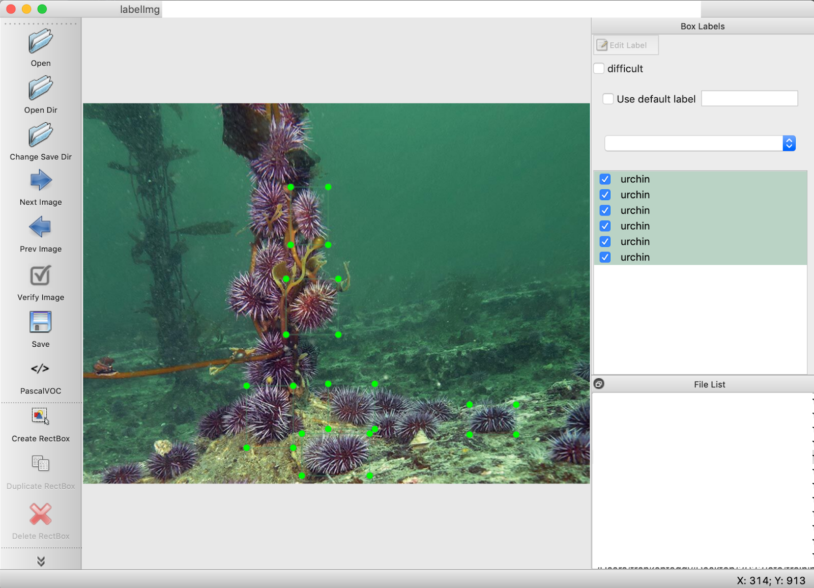
Present methods of culling purple sea urchins include the time-consuming task by divers to collect each urchin one by one and place them into a bag.
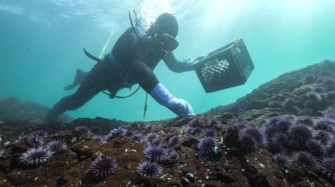
Diver collecting purple sea urchins by hand. Photo source: Sierra Rose Garcia [7]
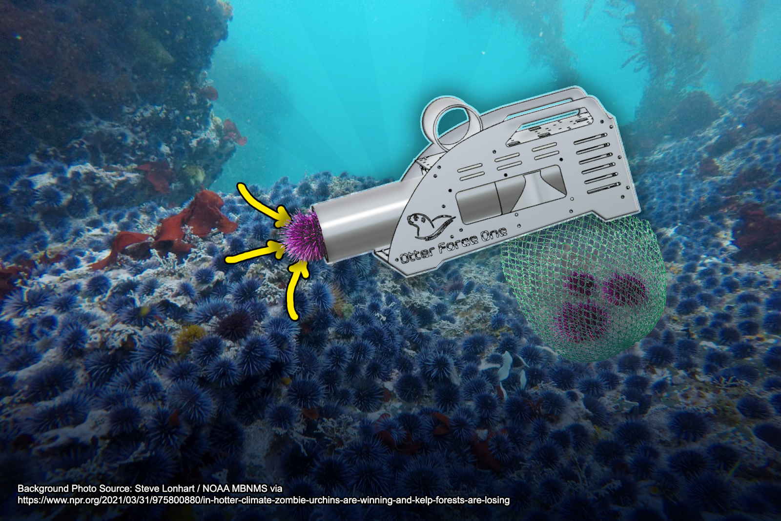
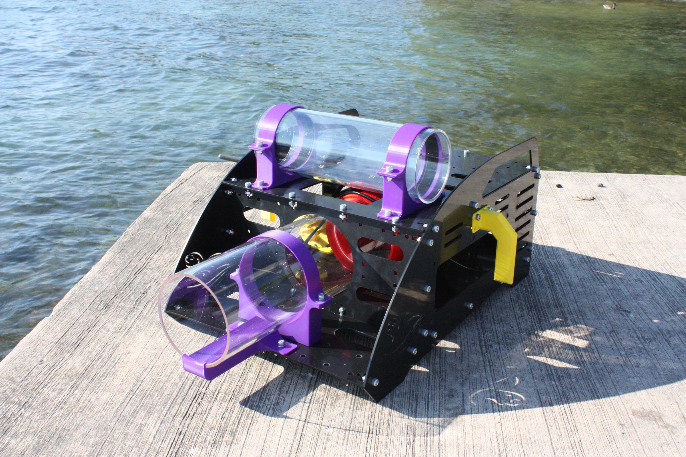
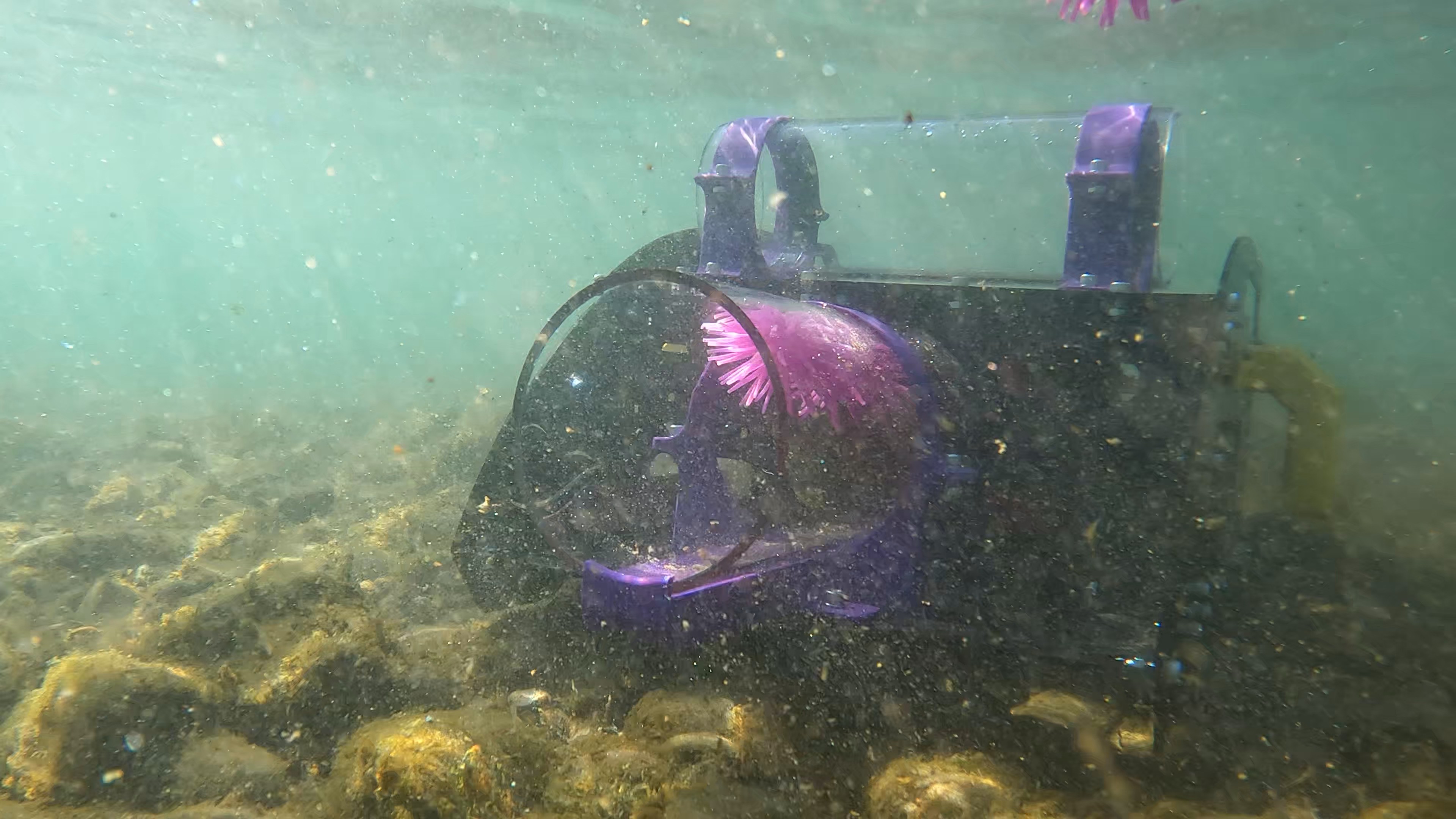
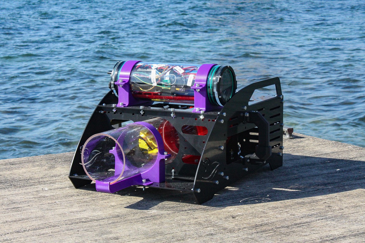
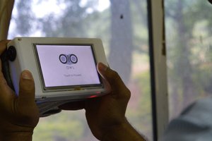
Otter Force One detects and captures purple sea urchins to protect kelp forests.
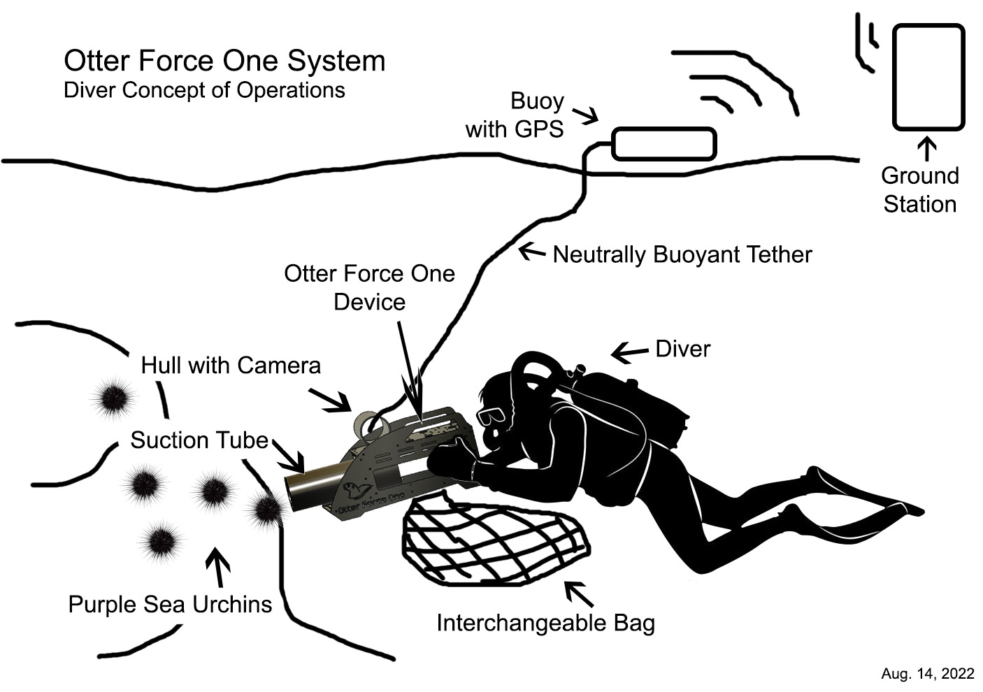
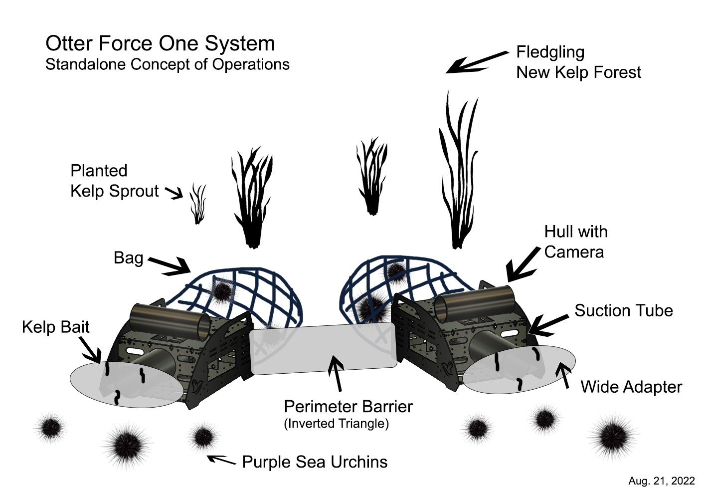
The device can be used hands-on by divers or as a standalone autonomous benthic device.
By placing these devices around the perimeter of a kelp forest, ongoing protection can happen even without divers present.
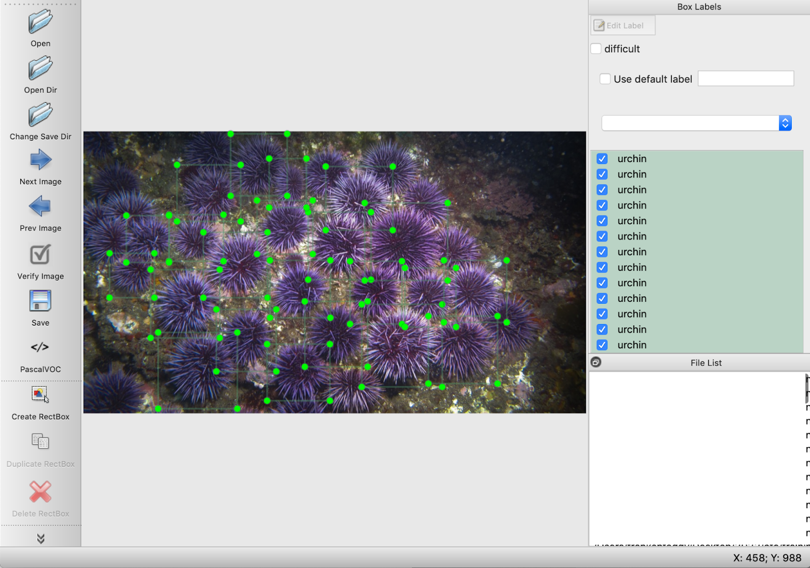
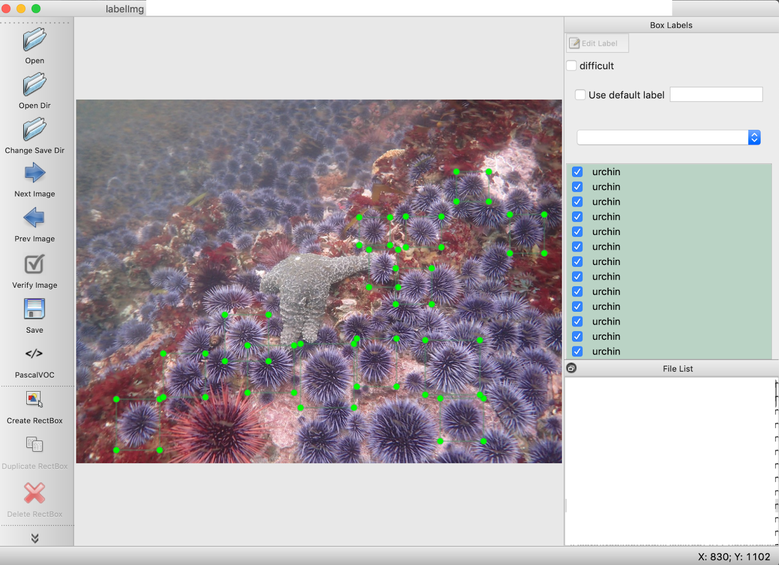
Otter Force One detects the urchins using its camera and AI. It automatically pulses a jet of water to dislodge the urchin. Then activates suction to bring the urchin into a bag non-destructively. Data of the number of urchins per meter squared is recorded to monitor progress.
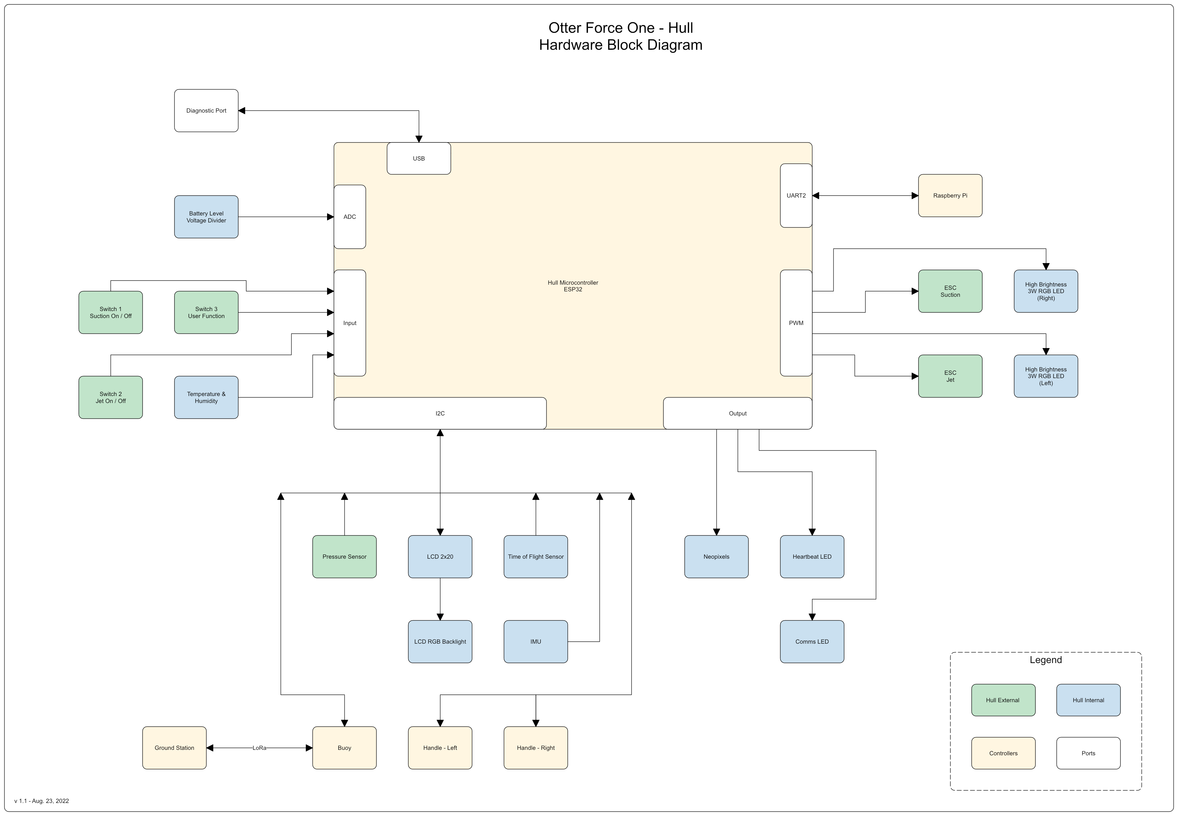
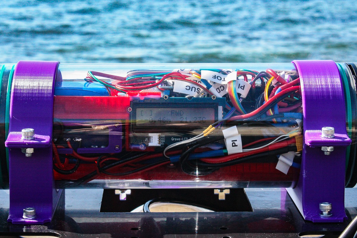
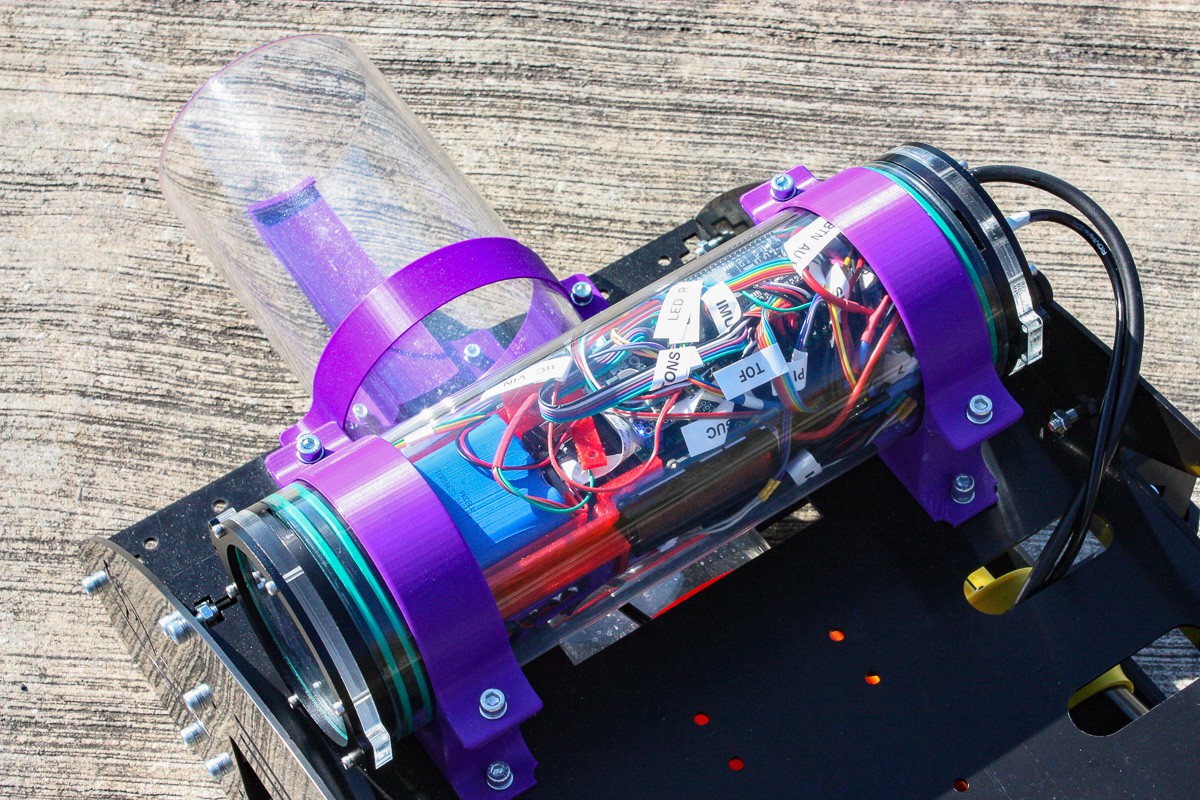
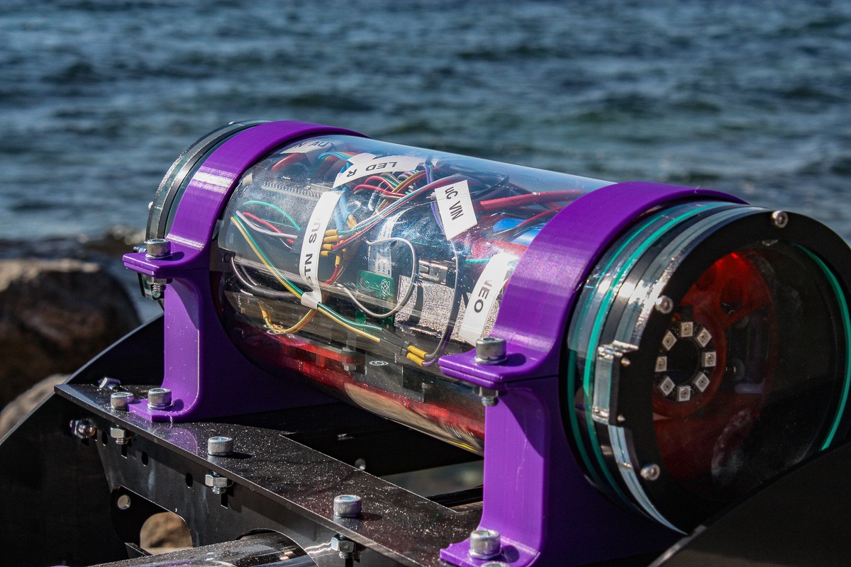
The core system is structured as follows:
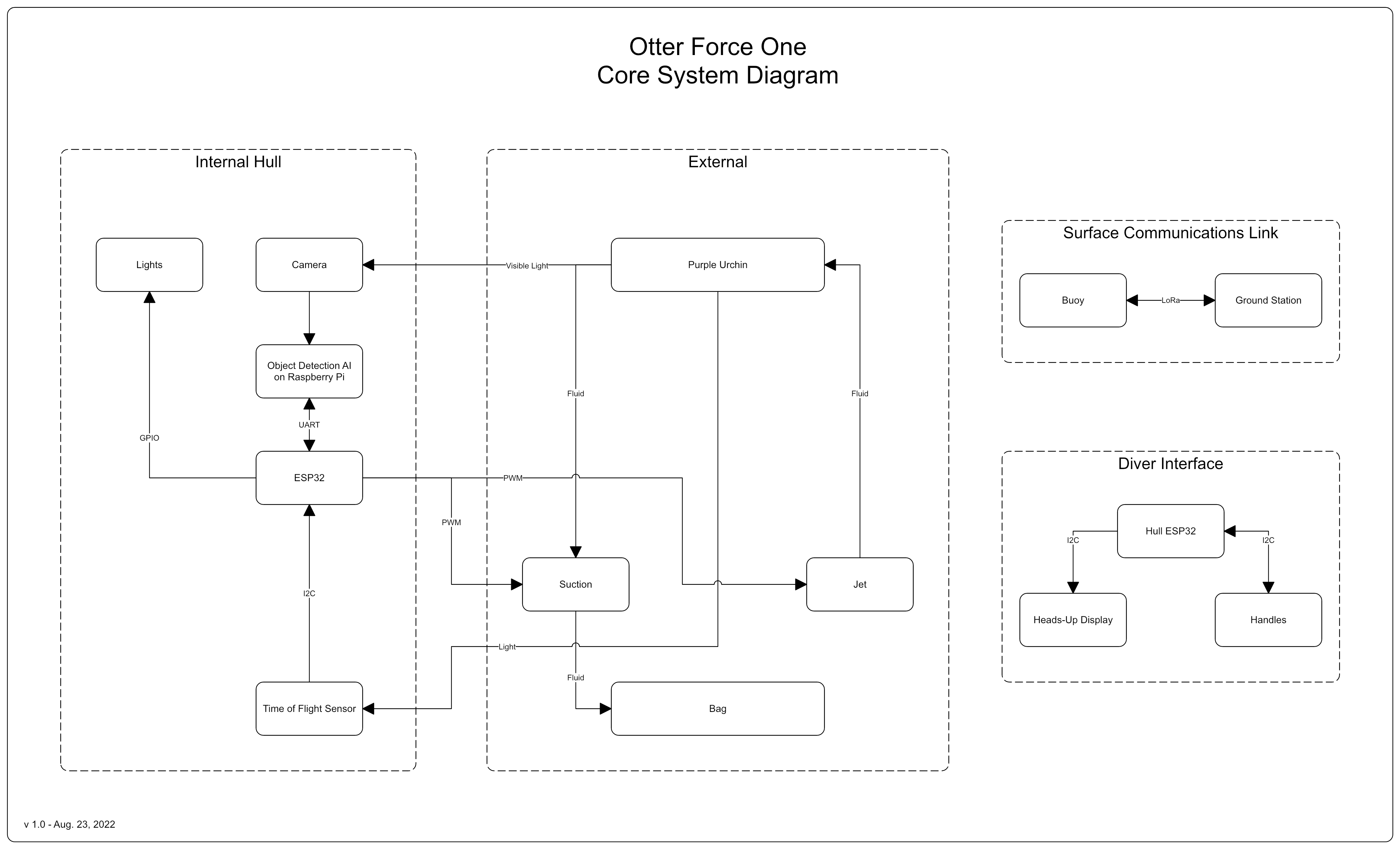
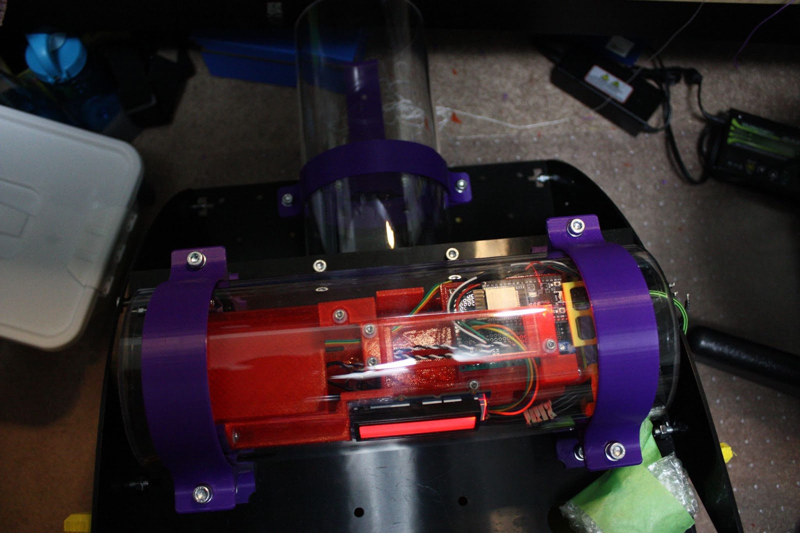
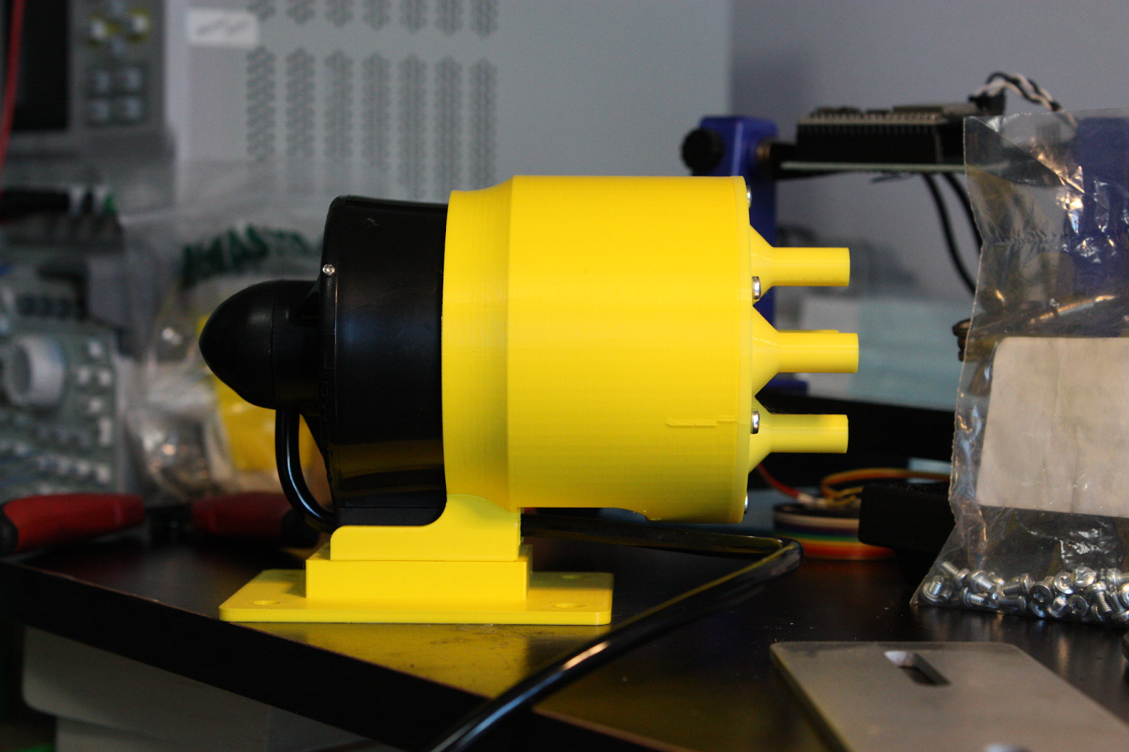
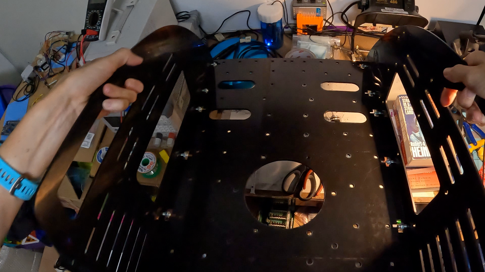
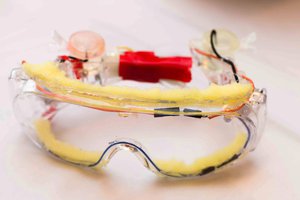
The primary hardware is located in the internal hull.
The device prototype measures 34 cm tall x 38 cm wide (50 cm with handles) x 68 cm long. Miniaturization would occur in the next iteration after proven functionality. The CAD model can be found in the Github repository here.

Human intervention is needed to restore the delicate balance between kelp forests, sea urchins, and otters. Otter Force One places this tool into the hands of divers to address this global climate related problem in their own local region.
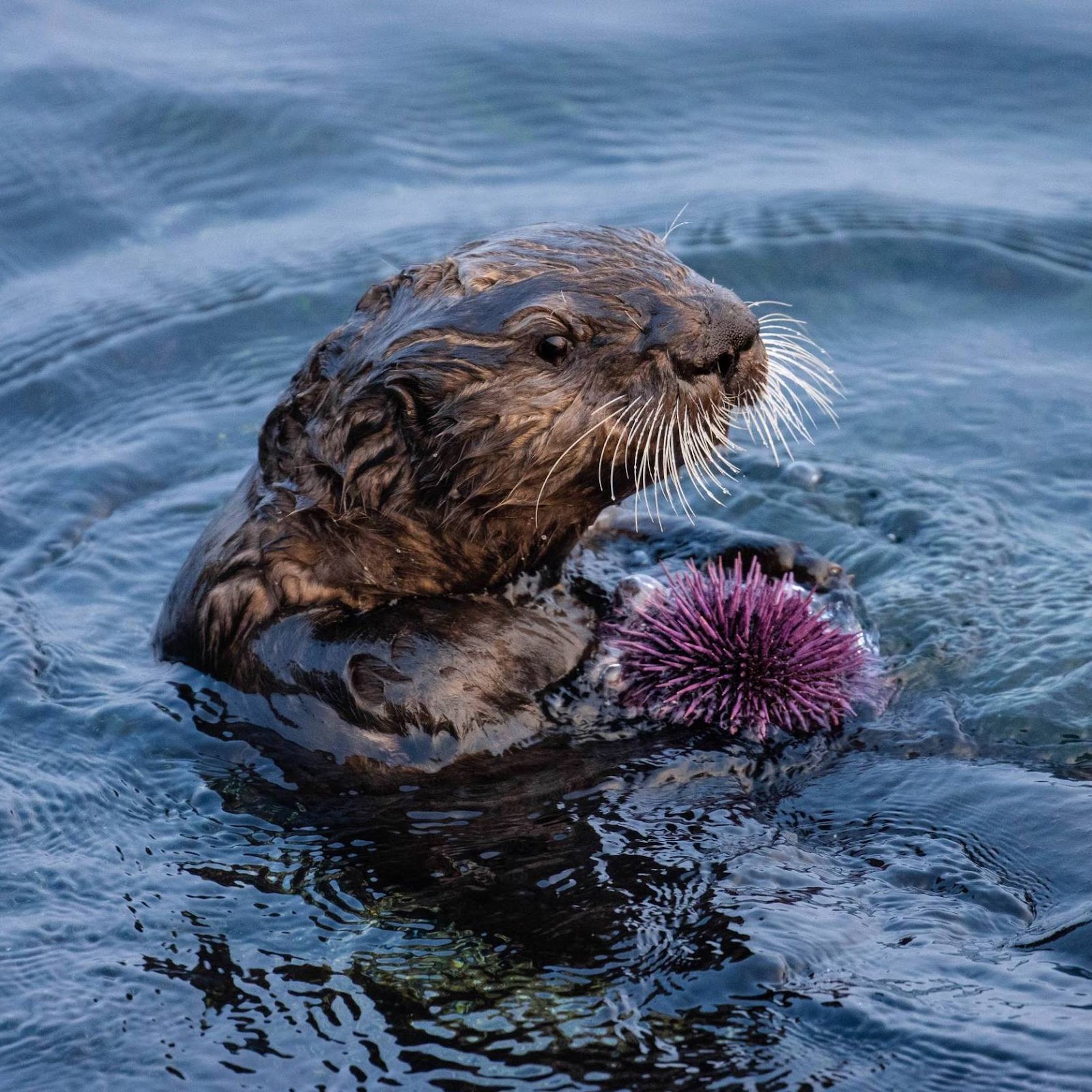
Sea otter with a purple sea urchin in Monterey Bay, California. Photo source: Morgan Rector [9]
The grazing purple sea urchins offer little to no nutritional value to otters. Thus, otters are not eating them. Otters are an endangered species. It is a delicate balance, as the below infographic details:
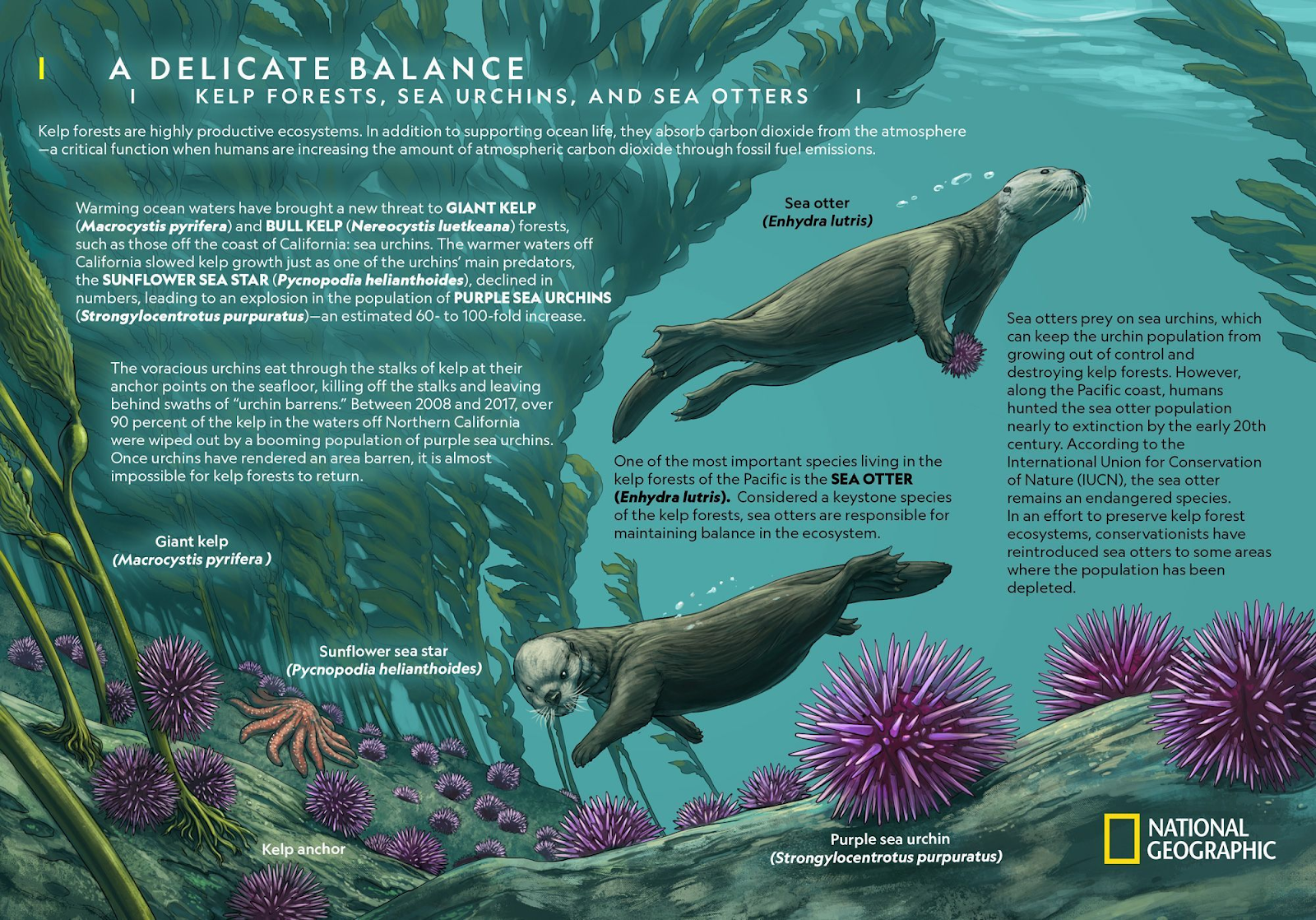
A Delicate Balance. Infographic source: National Geographic [8]
The Otter Force One prototype is in active development for the Hackaday Prize 2022 to address this massive climate related problem.
With the proper resources to further the prototype, solving the first step of the problem is possible. Join us on the journey to protect kelp forests with robotic collection and monitoring!
Let’s dive into more information in the following sections.
Development
Project logs table of contents
Problem
Kelp forest decline is a severe climate problem covering a large scale, magnitude, and speed [1]. More than 90% of kelp forests along 350 km of coastline in Northern California were lost [10]. With over 360 million acres of kelp forests around the world [11], the problem is global — Tasmania lost 95% of its giant kelp canopy [12].
Seaweeds (including kelp), store ~170 million tons of CO2 each year — thereby removing it from the atmosphere [13]. Kelp plays an important role in marine ecosystems by harbouring a greater variety and diversity of plants and animals than any other ocean community [14]. As well as protection for otters, which are apex predators of the marine nearshore environment [15]. Kelp forest loss is a climate driven catastrophe from multiple phases: loss of sea stars due to disease [16], a marine heat wave [17] which reduced marine oxygen levels [18], deforestation, and finally sea urchin barrens.
An urchin barren in Monterey Bay, California. Photo source: Michael Langhans [6]
Using satellite imagery, the decline in kelp...
Read more »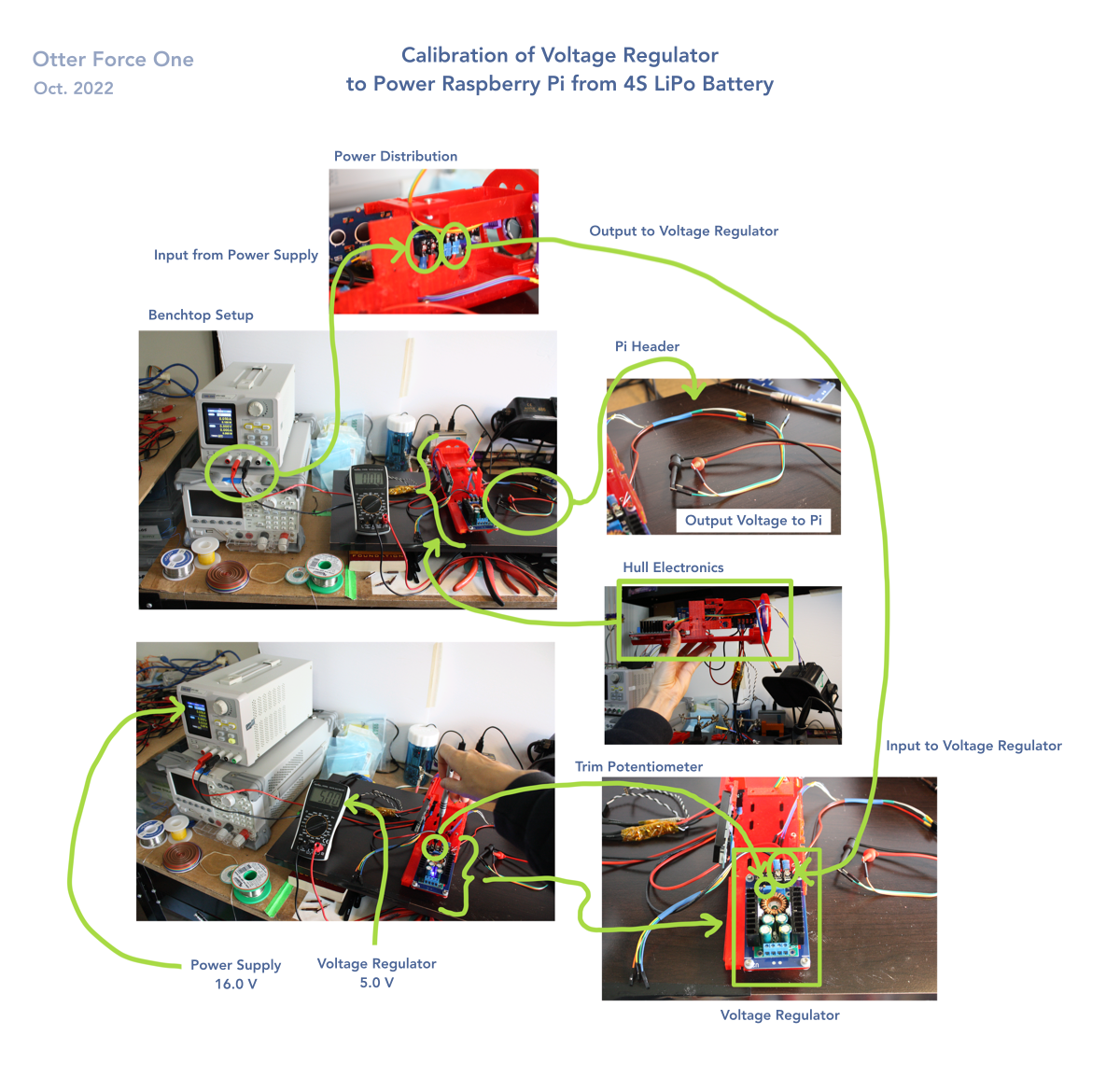


 spandana.cheruvu
 John Opsahl
 Suraj Singh
This is such a cool project. If you want a sensor pack from the OpenCTD, I'm happy to send one your way.