 EK
EKThe tubes for suction and the hull have arrived, along with the cut pieces for the device. Brackets, mounts, and structural elements are being 3D printed around the clock. Let’s take a look at what has been created so far:
Coupler
The coupler routes the incoming urchins to the bag. It attaches the suction tube to the suction thruster to the device, then to the bag.
Coupler in device with side panel and top panel removed
Coupler split into 4 pieces in CAD | Coupler cross-section view |


The model was split into 4 in order to be printed. The total print time was ~30 hours. The pieces were attached together using 100% rtv silicone.
Coupler curing outdoors | Applying silicone |


The mesh to protect the suction thruster was cut from a template from the CAD model and attached using 100% rtv silicone.

Applying silicone to the screen mesh
Front view | Back view |


Another way of fabricating this could have been with PVC pipes. This route was not chosen due to lack of space and tools for cutting and gluing. The advantage that 3D printing gave was an all-in-one assembly, with the mesh screen mount being included. In a production setting, this piece would be injection moulded.
Device
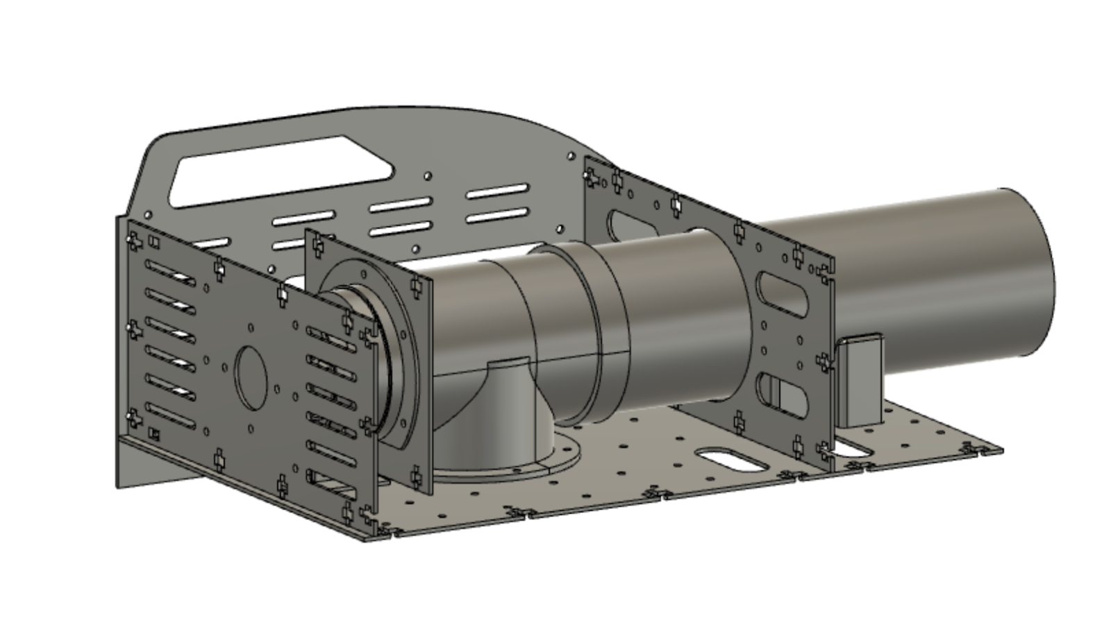
Preliminary CAD model:
Front view | Top view |


The material selected was 1/8" black delrin. This was chosen because of its performance in fresh and saltwater, as well as the malleability of the material as it might need some adjustments.
This first iteration of the design does not use interlocking tabs and slots because of modifiability of the plates. In the future, implementing this into the design would increase the sturdiness.
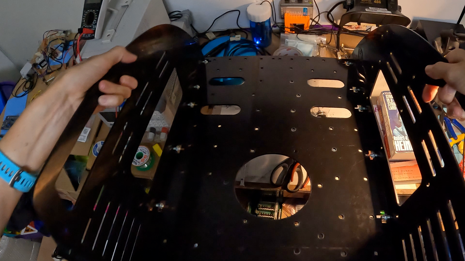
Side pieces attached! Testing the handles
M6 fasteners were selected | Attaching the pieces together |


As each side panel was attached to the base, the less it would warp and bend.

All four side panels attached to the bottom piece
There was a small error in the design. The side entrance of the fastener (the rectangle, as opposed to the hole), was 2 mm too small for the width of the fastener. In order to remedy this, a dremel was used to shave off the small amount. Safety glasses and a guard were used while cutting with the dremel.
Dremel with guard | Dremel with a conical sanding bit |


Two brackets have been completed so far, which are supports for the suction tube:

Water Jet Thruster
Water jet thruster sub-assembly CAD model | Cross-section view |


The design of the water jet thruster is such that a collar is attached to the mount which has heatset inserts in order to attach a plate to it.

Inserting the heatset inserts to the 3D printed collar part
Front view | Side view |


Through a submersion water test, it will be determined if the fasteners are strong enough for the water force as applied by the thruster.
Hull
Here’s a preview of the internal hull without the electronics:

These pieces are printed, and will be assembled in the near future. More about the internal hull in a future update. Until then, check out the hardware block diagram in the project description.
—--------
The current goal ahead of the Sept. 4th deadline is to demonstrate the suction working to collect an example urchin prop. Stay tuned for further updates on the progress!
Discussions
Become a Hackaday.io Member
Create an account to leave a comment. Already have an account? Log In.