 EK
EKBefore moving further along with placing the electronics on the 3D printed pieces, the voltage regulator has to be dialed in. It will output 5.0 V for powering the Raspberry Pi. This would be supplied by the 4S Lipo battery. In this setup, a benchtop power supply is used.
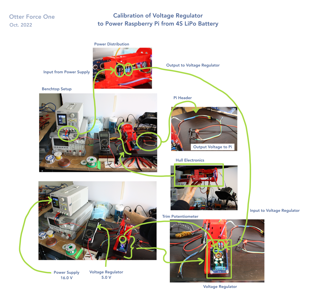
Here are all the electronics on the 3D printed pieces that will be inserted into the hull:

This is the voltage regulator. It is a switching module soldered onto a custom pcb that has a 4 pin barrier block for easily attaching wires with crimp connectors to. The trim potentiometer on the left is what changes the output voltage. The trim potentiometer on the right changes the current that the LED lights up with red - by default it is blue under that current amount.

Here is dialing in the voltage regulator - by reading the output on the multimeter while spinning the potentiometer.

The result: Powering up the Raspberry Pi from the 4S LiPo battery with the voltage regulator worked!
Discussions
Become a Hackaday.io Member
Create an account to leave a comment. Already have an account? Log In.