I have needed a 4-20mA output for multiple projects over the years, and I've had to build converters using Op Amps that are driven by filtered PWM outputs. It works but I've never really been happy with them. So I finally bit the bullet and designed one that can be connected to a SPI bus so that I can just set the output digitally.
The digital part is handled by a MCP4822 (a dual 12bit DAC), the analog part is handled by LM324 quad Op Amps, BCP56 npn transistors a precision voltage reference and associated resistors. I included course and fine trimmer pots for independent ZERO and SPAN adjustments for fine tuning the outputs.
I laid out the schematic and pcboard using KiCad and have created a BOM and POS file for submission to JLCPcb for manufacture and assembly.
The components in the schematic file have an additional symbol field that lists the JLCPCB component part numbers.

 flow
flow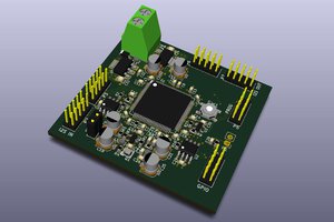
 togorean.bogdan
 Keith
Keith
 J. Ian Lindsay
Yep, you are very correct. I updated the pictures and data files.
Thanks for spotting that.