Close
0%
0%

A Wheel

Another Satisfying Single
Wheel
Terrifying Hoverboard Conversion

Similar projects worth following
The existing hoverboard controllers have nice IMU's, proper sturdy (and replaceable) N channel mosfets with discrete high side drivers, current sensing/limitation, audible warning after loss of power, and field oriented control coupled to three hall sensors per motor. That is a really solid setup actually. I'm keeping it, with minor changes.

So this is my one wheel vehicle from:

A hoverboard with a bad battery
A very nice sized salvaged 8S Li-Po battery pack
A zero turn radius mower tire
Garage wall storage rail
Scrap AL angle
A healthy dose of cut, scored, and bent poly-carbonate
A touch of light-sabre building experience
A couple 3D printed parts
A new appreciation for sealing 40psi with 3D printed parts

770W from the two hub motors with my 8S battery.
15mph top balanced speed.

Also, the conclusion that I should not be allowed to play the acronym game
- The project formerly known as ASS Wheel THC

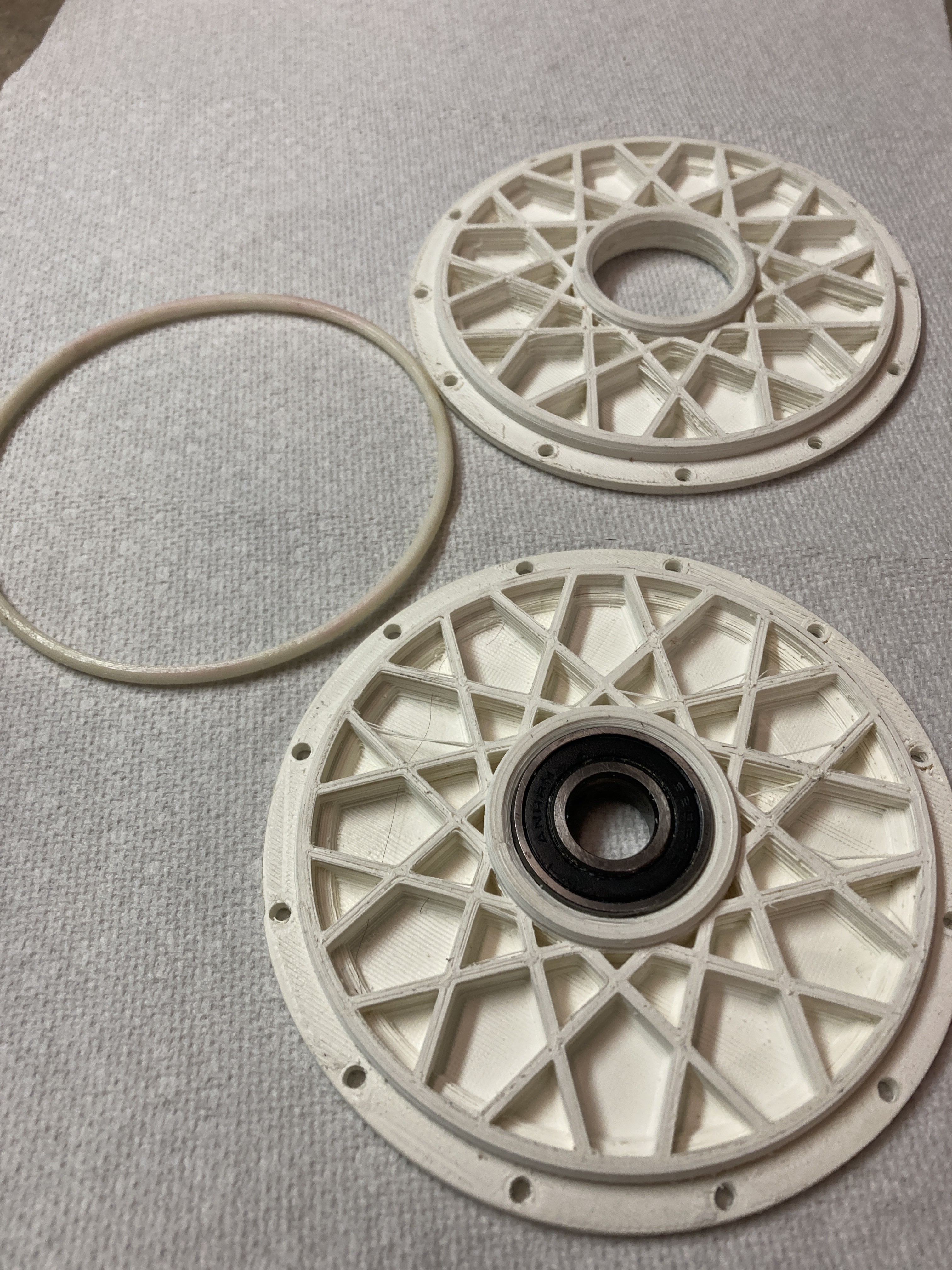
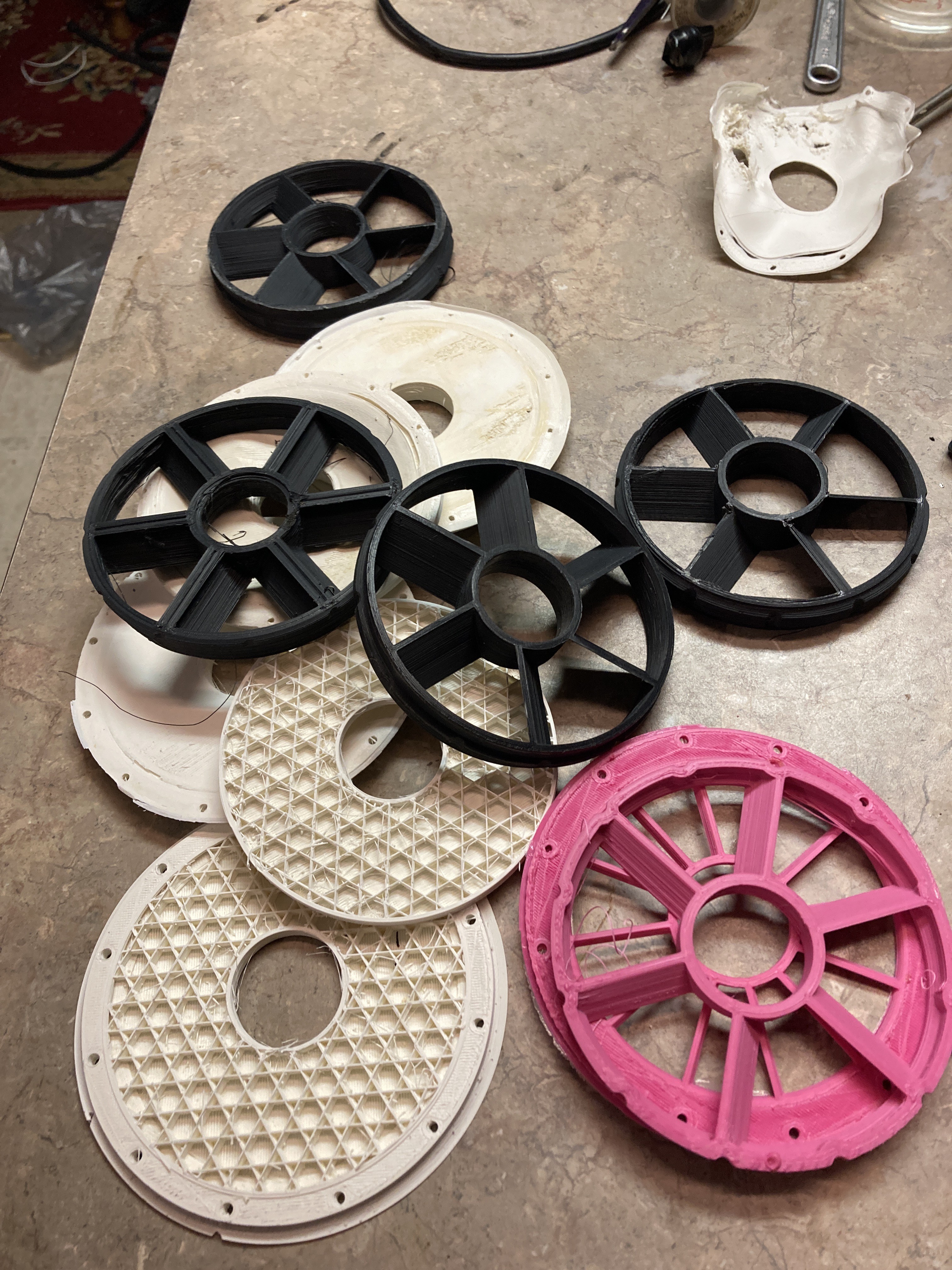
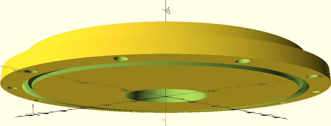
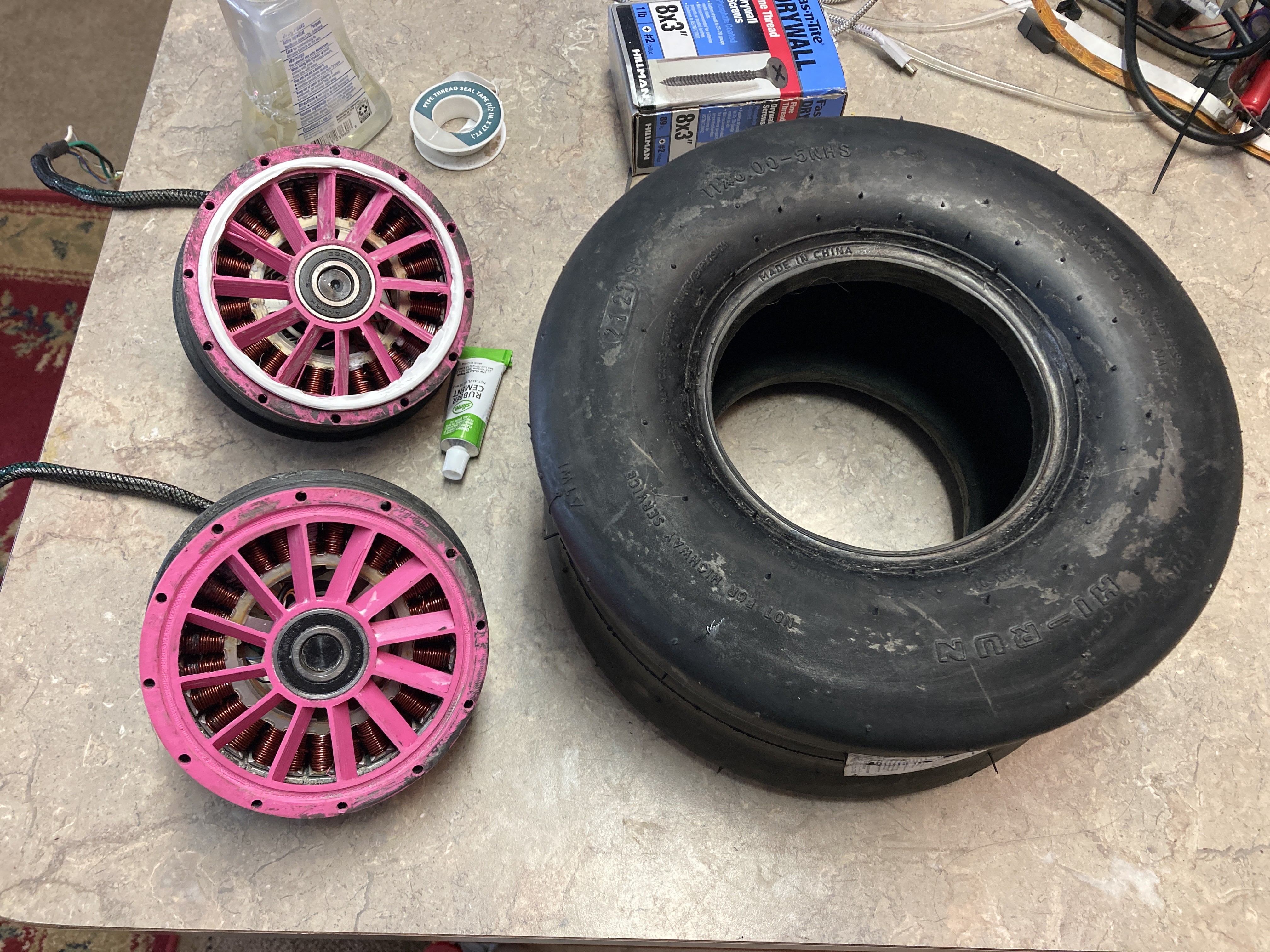
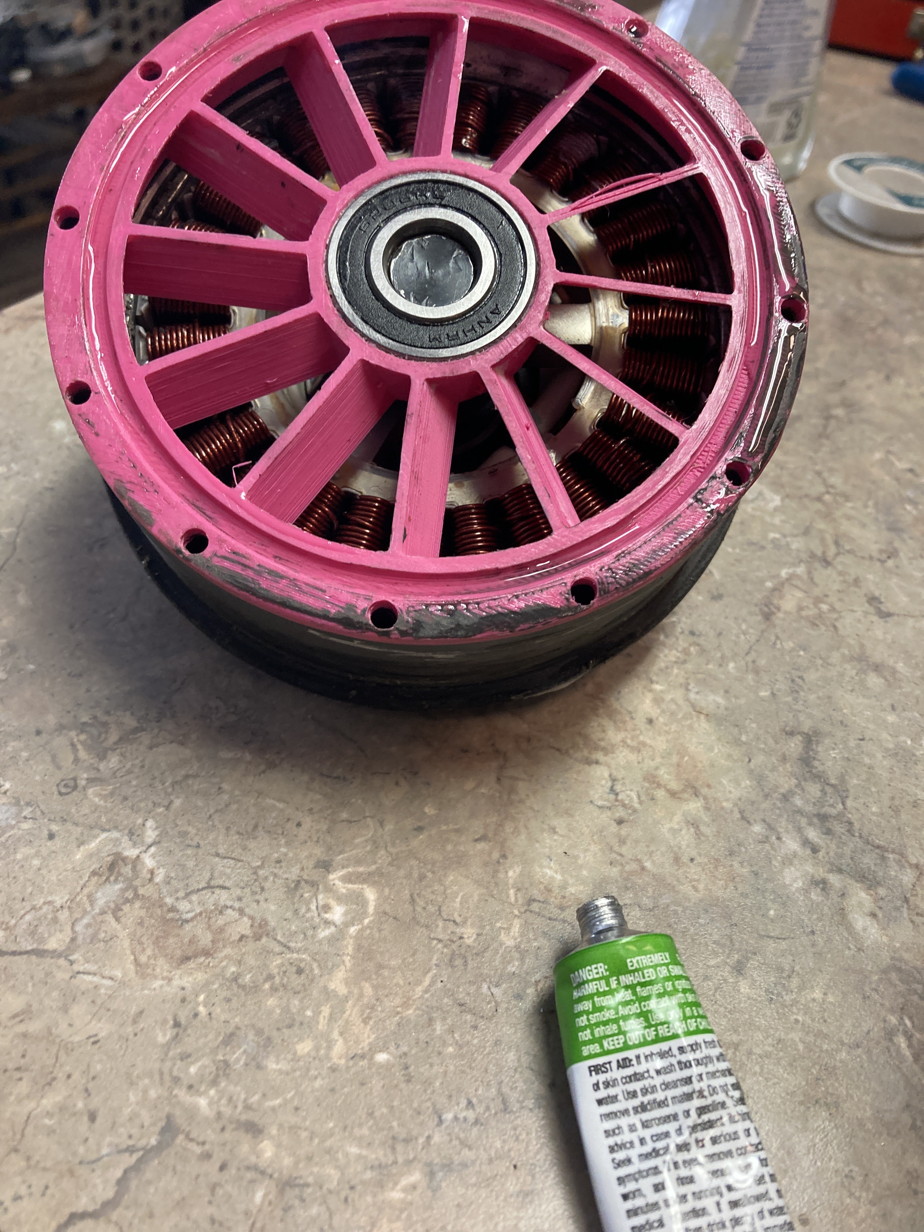
This is only one hub, and it is going in the wrong direction.. but it is a start.

Estimated output per hub is at 390W by moving from a 7S to an 8S battery. So total power output should be 780W.

Not all of that will be usable as balance needs to be maintained.  

Scaled up from the donor hoverboard tire dimensions this puts the top balanced speed at ~15mph, but this does not account for the voltage increase.  

Soon to be measured.

Standard Tesselated Geometry - 2.60 MB - 09/11/2022 at 15:10

Download

Standard Tesselated Geometry - 6.46 MB - 09/11/2022 at 15:10

Download

x-openscad - 3.52 kB - 09/11/2022 at 15:07

Download

MPEG-4 Video - 1.05 MB - 09/05/2022 at 17:04

Download

quicktime - 24.30 MB - 09/05/2022 at 16:26

Download

  • In the flesh

    Daren Schwenke09/12/2022 at 14:27 0 comments

    Hubs are done printing, in all their accidental 2 walls glory.  Minus some surface issues they turned out perfect. 

    For the robot uprising archivists, that is a bit of my hair embedded in the print.

    Dimensions are all right and a skim coat of epoxy will take care of making this hold air.

    Those will be some unforgiving camera shots of parts to come: white prints, black hubs, gray epoxy.

    The o-ring groove printed perfectly, in all it's 8 sided glory. 

    I have the old hubs split, the tire off, and nearly ready to go back together. 

    Wow, rubber cement is strong…

    The post mortem of the previous two hub failures is as follows:

    For one, the hub shaft was pressed during tire assembly.   

    Pressing the shaft caused the inner bearing to push through a bit, creating a gap internally between the bearing stop and the bearing.  A wire got caught in there and on final assembly got squished.

    The other one the ground wire broke, somewhere, if I had to guess right where it goes in the shaft.  Probably the ground wire.. due to the strobing effect it had on the lights.  I won't know.  I'm replacing all of it with stranded wire.  OOOoooOooooooo (I found a nice PS2 mouse cable which is perfect for this).

    I think I will at least turn them on this time before epoxying them.  

    Perhaps run them fully assembled, minus the tire and o-ring....

  • Rib it

    Daren Schwenke09/11/2022 at 14:29 0 comments

    Having a real problem with bed adhesion with the nylon. I’m out of Aqua-net and almost out of L’Oreal lock it. Acquanette works better for nylon.

    Going to give the ABS one more shot, hopefully splitting the difference between layer separation and warping if I can remember what setting caused each.  :)

    Printing this now:

    It has ribs built by extending the bearing tangent to the edge with an offset that resulted in an even spacing of ribs along the edge.  The offset was 0.

    The ribs and rim are multiples and result in pretty paths.  It has a more convex overall shape to lessen the tension buildup along the edge as those new upper layers contract and pull on the edges, and a thin layer at the bottom to keep junk out of the motors until assembly (again).

    Here is the problem.

    The groove for the o-ring is against the bed and splits the main body from the rim.

    I can move it in further, but right there it is basically right under the lip.  Nice straight transfer of clamping force through the part.  I wanna keep that.  Moving it in puts more stress on my print.

    One more time..

    Latest files are up, in the files section like this one:

    https://cdn.hackaday.io/files/1869067996586304/a-wheel.scad

    <edit>

    Slicer defaulted to 2 walls and I didn't catch it. 

    We'll see how that turns out I guess. 

    Probably more dimension ally stable as the excessive infill will allow them to flex more.  Just hope it holds together.

    And then I accidentally printed it at 120 mm a second until now as I was using the brim thickness to level the bed. I noticed because it turned into this little chittering beast as it was doing triangle infill.

    Not bad… I usually design and print structural parts and so solid ribs are a thing with me but this is actually working kind of well. There’s an overhang right at the start of the bearing area that didn’t fare well but everything else looks great.

    White ABS, printing at 260C hotend, 70C bed, enclosed (well I'm missing the front edge of my printer, so mostly enclosed), with no print cooling.  Looking good.

    </edit>

  • The Boulevard of broken hubs

    Daren Schwenke09/10/2022 at 19:44 0 comments

    I can't print that part in my chosen -> (abundant) prototyping filament.  ABS.

    The Boulevard of broken hubs. 

    The white ones are the latest ABS. The black and magenta ones are failed attempts at sealing without using an O-ring.

    Whooo hooo... *cough* ho. *cough* *cough*.  

    I hate ABS.

    The geometry either makes it pull off the bed on cooling at high temps, or have crap layer adhesion and edge cracking at the geometrically accurate temps.  

    Anyway, it is probably better to change the geometry rather than provide people with one part that is stupidly hard to print without warping, warping ruins the part as the edge thickness is critical, and it happens right at the end.. every time.  I quit.

    I tried wacky things like applying temperature gradients to the part by mucking with the bed temperature during/after printing.  

    Note to self: you can't anneal parts with massive voids.  The massive voids collapse and you have a warped mess.  

    You *can* anneal solid or nearly solid parts, right on the heated bed if your bed goes high enough.

    Annealing relieves the internal stress of your parts.  They get stronger, and shrink asymmetrically.  Simple to deal with for flat parts with no voids.

    I actually think I am going generate a conservative/strong anneal able model to run nylon.  I just remembered I have some.  A little test roll.

    And I also have some suitable PTFE for rebuilding the liner of my non all-metal hot-end when it eats itself somewhere during running nylon, and some stainless threaded rod when I get desperate later when that fails and build a new throat from scratch in desperation.

    I'm going to change back to a variation on the spokes again, perhaps one optimized for single path 3D printing.  :)  

    If you make your spokes and wall dimensions a multiple of the nozzle size, you can count these so they end up adding up to the same number of in/out trips.  Then the slicer can draw this as a much more consistent extrusion and your parts are stronger and shrink along nice concentric paths during annealing.  

    Or so goes the plan.

    Tonight.

  • Going to rebuild the hubs

    Daren Schwenke09/07/2022 at 21:48 0 comments

    My second hall sensor is now flaky. 

    This one I damaged when I swapped the wheel left to right and so had to remove and re-install the wiring.  So now I get to pry out my epoxied in hubs.  Glad I can still split them first.  That would really suck (and was considered).

    I was also thinking about just printing the bearing plates for the hubs as 15% grid infill, as a solid.  

    <edit> Like this

    </edit>

    It may perform better...

    Earlier I had mentally tossed around the idea (and never mentioned it) of putting a tablespoon of mineral oil in each hub, hence the previous vaned/open design.  Oil pump for my oil cooled hubs.

    I think dead space might serve me better as the cooling surface is all at the opposing face anyway, opposite where my hub is.  Less oil would do more work and less sloshing around and getting in the way of rotation.

    If they start to get hot, they are getting a bath.  I can inject the oil after assembly through the shafts, after I seal the wires within the shaft and add some capillary tubing.

    Rebuilding/reprinting the hubs.  Disassembly later.

    <edit>

    Build plate not perfectly level.  Big, flat part. Part lifted on the back corner.

    Re-leveling.

    </edit>

  • Loops

    Daren Schwenke09/07/2022 at 16:11 1 comment

    Oops.  The ground line has come off of  the hall effect sensor board inside the hub.

    You know how I know?  Cause as leg each of the hall sensors trigger, the wheel lights turn back on as they now have a path to ground.  Loops.

    So run with one controller, hotwire across from the other controller, or break apart my epoxied hub...  I'm thinking.

    I may be running into the preset current limit for the controller boards.  Either way, I don't like the value of the existing sense resistor, so we are going to change that.  3R5 aka 3.5 Ohms.  I'm running 12 gauge wires to the motors to be fed through that.  No.

    I soldered some 10cm loops of 30? gauge wire across the sense resistors as I didn't have any low value resistors suitable for this.  A quick glance at the resistivity per foot for about the gauge I think this is, puts this in the range of between 0.7 and 1 Ohm of resistance.

    Soldering this across the existing resistor should then be 0.6 to 1 Ohm.  I can't actually measure it right now, but it is lower and in the right range.  I need a four lead and I don't have one here, and I just jumpered across my previous known value for establishing a voltage drop at current.  :)

    I am guessing that the low current limit here was not for the motors, but for the pathetic 7S-1P 2Ah battery this came with.  Had a nice BMS though..

    I have ~5x that battery capacity now, and no BMS (yet).

    This modification moves the upper current limit from whatever it was to ~4-5 times that.

    Given the previous relatively huge value for the sense resistor, I think this will increase output.  

    The existing controller mosfets, wiring, and cooling will have no issues handling the extra current.

  • Wrong way, Hal

    Daren Schwenke09/04/2022 at 23:21 0 comments

    <edit>Or I can just swap the motors. That worked.

    </edit>

    Looks like I swapped the controllers from left to right as leaning forward goes back and vice versa, but hey... it powers on.  

    It has some scary acceleration on that un-inflated tire, while reversed.  Heavy part in the front.  I can't imagine that would feel good to ride.  

    This is only one hub/controller.

    The math puts each hub/controller as contributing ~390 Watts with my 8S battery.  This is before any current sense modification to the controller boards.

    Also, the controller boards seem to be fine with accepting and using the 33.6v from my fully charged 8S battery.  The original battery was 7S so there was a possibility that it could have over-voltage protection that could trip.  It did not.  Yay.  I wonder how high I could go?  I got room for another 4 cells if I could find them..

    But.. there is another problem.

    My hall sensor rotation has been flipped.

    By flipping the shafts of the hub motors end for end I have forever changed the forward rotation direction.  This matters as the controllers only creep along in reverse.

    Normally, just swapping any two wires on a sensor-less BLDC motor would reverse the rotation, but these motors have a hall sensor per phase and are fully sensored.  This allows perfectly accurate commutation at very slow speeds, but it also requires that the hall sensor position line up with the mosfet output.  

    I can't swap wires.  The sensored motor only runs correctly in one wiring combination.  You can try the rest of the combinations without damage (briefly to prevent overheating), they just don't work.  No easy reversing of rotation with swapped shafts without swapping some hall wires at the same time I swap motor wires.  Oof.

    Unless perhaps I cross the wires.  

    Good heavens no!

    Having the left controller power the right motor may just give us the anti-backwards molecular inversion that we require!

    Wires... not... long... enough...  The hall wires are long enough, but the winding wires are just barely.. not.

    It is a good thing I keep these assorted lengths of wire.  Have I shown you my assorted lengths of wire?

  • Slime acquired, car broken

    Daren Schwenke09/04/2022 at 21:55 0 comments

    I need to verify proof of life for the whole setup, then I can Slime the tire and get rid of that pesky leak.  It would suck to slime it and then find out I pressure washed off the enamel of two adjacent windings (happened) and failed to repair them, and having to crack it all open again, this time coated in slime.  Yeah.  It's going to spin first.

    However, the solenoid of the starter in my Saturn Ion decided to stop functioning today.  

    I have lost many hours and still need to rebuild a starter.  My running theory is cleaning, lubrication, and some 2000 grit may just bring it back.  Just the solenoid if I can get it off straight away...  

    The new starter was $179 and wasn't in stock anyway.  Car cooling.

  • Controller and headlight mounts

    Daren Schwenke09/03/2022 at 21:59 0 comments

    I took the heat sinks off the controllers and replaced them with some U channel.  That let me mount them to the side rails and tilt them via a screw I threaded into the channel.

    This will let me to adjust the ride angle as I can now change where the hoverboard controllers thinks level is.

    This also lets me fine-tune both sides so they are providing the same RPM to the now physically coupled hubs.  I'm just going to go for greatest RPM, while close to the same angle.

    This is an extreme example.  I'll probably tilt the controller boards about 5 degrees to start.

    My top front decking is going to be rather springy given it is basically a 3/16" suspension bridge of two layers of acrylic/poly carbonate.  I need the area metal free to detect the rider via cap-sense, but I could just as easily fall back to a micro-switch.  I wanna try cap-sense.

    Taking advantage of the flexibility of the deck, I mounted the headlight on rubber.

    Pressure on the front deck will now aim the headlight up.

    I think this will translate to the headlight giving you a look further down the trail when you are going fast.  Or it just may stay 'level'.  Either way, still cooler than a static mount.

  • The money shot thus far

    Daren Schwenke09/03/2022 at 19:31 0 comments

    Just behind the axle I slid in some bar stock that was tapped.  I forgot about it.  Adjustable laser mount!

    There is a nice spot in the front there for a hunk of spinning iron for imparting roll into the body.  I am not sure how effective using roll to generate yaw would be, but pitch the hoverboard takes care of for us.  Pipe dream.  No really.  I think a BLDC motor with a bit of pipe around it would make a passable reaction wheel for this application.  Alternately for imparting yaw, a flywheel from a model steam engine also driven by a BLDC would probably make a really nice reaction wheel.  If accidentally launched into orbit, we would be able to orient ourselves rather effectively, until saturation or our batteries out gassing does us in.

    The last two entries shall be stricken from the record.  Moving on.

    I still have to terminate the new wiring to the old connectors for lights.  I don't know if both controller boards have separate 12 volt buck converters, but I'm not taking any chances.  Each side for lighting is staying independent and +12 volts is not being shared.

    The tire has a slow leak.  Sad, but I'm satisfied my o-ring area is stable, so I'm just waiting till the tire can spin on it's own, and Slime (tm) ing it.

    The battery compartment pre-mylar.

    Tail lights will need some thin foam or a few layers of mylar for diffusion.   

    Inside of the poly carbonate needs some a suitable image printed and stuck in there, or a little creative painting.  The poly carbonate does not respond well to being cleaned after painting, so that little bit will be waiting until it is assured.  I have some ideas about painting a mist of chrome through fish-nets if no suitable image is produced in time by my son...

    The headlight needs a mount, and I need to build the front foot area lighting and such yet.  There are two indicator lights from the hoverboard I want to save: Low battery and power.  I'll be shining them through the front foot area I think.  I would prefer the side rails if that is visible to the rider.  It probably is not.

  • Tire mounting

    Daren Schwenke09/03/2022 at 17:09 0 comments

    Got the crud out of my hub, so tire mounting is happening. I lubed the bearings good as well because this is probably the last time this gets taken apart until the tire needs changing.

    I can’t imagine that happening for a very long time.

View all 23 project logs

Enjoy this project?

Share

Discussions

stefan.schnitzer wrote 09/12/2022 at 18:54 point

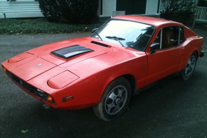
I hope you will succeed and build a drivable one-wheel. I had to convert mine into a scooter https://hackaday.io/project/180964-diy-electric-one-wheeled-vehicle  

  Are you sure? yes | no

Daren Schwenke wrote 09/12/2022 at 19:36 point

Oh yeah what I’m doing is loads less work. Starting with the hoverboard means this project is almost just some clever re-packaging.

Hopefully that means less roadblocks, but I am sure I will make up for that by creating some new ones.

  Are you sure? yes | no

Simon Jansen wrote 09/03/2022 at 18:09 point

This looks very cool indeed! A lot of work before first roll though. I would be too impatient, try it out before it's ready, crash and burn.
Where did you get the idea from? Are you following plans or making it up as you go?
You at least owe us a video of the first drive. Or X-rays / hospital bill or insurance claim.

  Are you sure? yes | no

Daren Schwenke wrote 09/03/2022 at 19:01 point

Trial and error, and good guessing.  I did take a look around before I ventured off here, but I like where this is going better.  Flipping the shafts around will allow a much cleaner build.  Using both controllers and a much better battery should also help with performance. The deck is also a nice thickness and still has room to allow reflector areas for lighting.  

You will be getting videos, of my son.  He has full pads.  I'll probably try it later on once I know it won't shut off at 15mph.  :)

  Are you sure? yes | no

bootdsc wrote 08/22/2022 at 02:01 point

Saw this while sorting by new. I like the idea of converting the hoverboard into a one wheel. Looks like a fun project hope.

  Are you sure? yes | no

Daren Schwenke wrote 08/22/2022 at 14:37 point

Thanks. I think it will be a blast.  The controller has proper mosfets, high side drivers, FOC.  I think all it was missing to excel was a decent battery.  I estimate 770w from the two hub motors if it will accept the 8S battery without freaking out.

  Are you sure? yes | no

Similar Projects

Does this project spark your interest?

Become a member to follow this project and never miss any updates