 Michael Gardi
Background
When we think about the dawn of the personal computer era, names like Apple, Commodore, Radio Shack, and Sinclair come to mind. That's because these companies were the big winners in this new market, selling millions of personal computers to first time buyers. There were of course many other companies competing for market share at the same time, with capable and innovative products, that didn't quite make the cut. Ohio Scientific Inc. (OSI) was one of those companies.
Formed in 1975, Ohio Scientific sold a wide range of computer products from the low end Model 500 single-board computer to high end Challenger III disk based business systems selling for $13,000 or more (in 1970s dollars). One of their most popular systems was the Challenger 1P, based on the upgraded single-board computer the Superboard II. The Challenger 1P was relatively inexpensive, selling for around $350 (US) in 1978, and the Challenger 4P sold in 1979 for $698 (US).
Inspiration
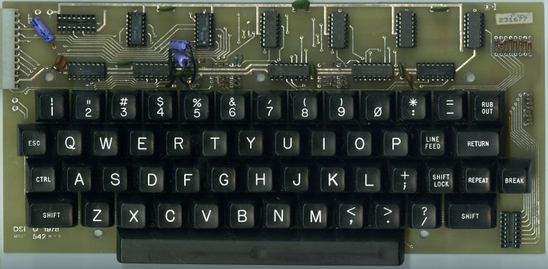
I started looking more closely at the Challenger 4P as a potential reproduction candidate when I was working on my MCM/70 Reproduction. But It turns out that the keyboard that I'm going to use for the MCM/70 is an OSI reproduction keyboard from Dave at osiweb.org since they were very similar. I used Dave's Sol-20 reproduction keyboard for my Sol-20 Reproduction and it worked out great. If you check out Dave's Unified Retrocomputer Keyboard Project on GitHub you will see that he also offers keyboards for Apple I, Apple II/II+, Generic ADM/3A teletypes, and most importantly to me OSI computers. This is what OSI keyboards looked like.
This got me looking seriously at the Ohio Scientific line of computers. I liked what I saw. I was an Apple II nerd back in the early 80s so a reproduction project that was based on a 6502 processor was very appealing.
So I have ordered an extra OSI keyboard PCB and stabilizer, OSI keycaps, and an encoder from Dave for my new Challenger 4P reproduction project.
Emulation?
There is a very active and robust OSI community out there. Here are a few links to get you started:
As a result, making a reproduction of many OSI computers is probably easier than it would be with other lesser known offerings from the era. For instance reproduction motherboard PCBs for many models including the Challenger 4P have been created based on 4000 DPI scans of the originals. I can see these on eBay for as little as $45. I'm not sure how much parts would be. These boards have somewhere in the range of 10-30 TTL chips per board, and you'd probably want machined pin sockets, so parts could add up. While this is something I might consider doing if I was making this reproduction just for myself, I'm not sure this approach would be for everyone. For all of my reproductions I try to design them so that anyone could make one for themselves. When a project is finished I always create an Instructable with the step-by-step directions I used to make my reproduction.
So my Challenger 4P reproduction will be based on a software emulator. While not as "pure" as a hardware implementation, this will greatly simplify the build for anyone attempting it.
A Challenger 4P Emulator
There is an existing emulator for OSI based computers. WinOSI is fantastic and can emulate many different OSI models and hardware options. If all you want to do is "kick the tires" on the various OSI computers, this is the way to go. Unfortunately because WinOSI is Windows only, it's not suitable for my purposes. I need an emulator that will run on a small single-board computer, probably a Raspberry Pi 4. Since there is no "portable" Challenger emulator I will have to create one.
Based on what I learned creating my Sol-20 emulator, the first step towards creating a Challenger 4P emulator is to find an emulator for the CPU being used, in this case a 6502. Because a huge amount of effort has already gone into writing emulators for classic video games, CPU emulators are quite common. A quick search on GitHub turned up docmarionum1/py65emu. I chose this as my starting point because py65emu was well reviewed (75 stars), and is written in Python which is my language of choice these days. Spoiler alert, it's great.
Memory Map
It's surprisingly straight forward to emulate a classic computer if you have a virtual CPU to build on. The devil of course is in the details. First step is to define a memory space for the virtual CPU to operate on. In the case of a 6502 processor this will be 64K of memory. Some of this memory will be allocated as RAM (Random Access Memory) and other memory blocks will be loaded with code and data that would have been in ROM (Read Only Memory) on the original machine. Some memory addresses are used as control interfaces. The memory map for the Challenger 4P looks like this:
| Start Address (HEX) | Length in Bytes (DEC) | Description |
|---|---|---|
| 0x0000 | 40960 | RAM Memory |
| 0xA000 | 8192 | 8K BASIC ROM |
| 0xD000 | 2048 | 2K Shared Video Memory |
| Accessed directly by video hardware. | 2048 | 2K Character Generator ROM |
| 0xDF00 | 256 | Keyboard IO Interface |
| 0xF000 | 256 | Cassette IO Interface |
| 0xF800 | 2048 | 2K Monitor ROM |
Once the memory has been defined and the appropriate ROM images have been loaded, you simply give the 6502 emulator a starting address in memory where the code to execute begins, for the 4P this is inside the Monitor ROM at 0xFF00, then start the emulator running. When I did this I was happy to see that the emulator did not crash. At this point I knew it was running but had no way of knowing if it was working as expected. I needed to see something working.
A Virtual Display
Now that I had a virtual 6502 (presumably) running Challenger 4P code, it was time to create some virtual devices, starting with the display. A Challenger 4P was typically connected to a monitor or TV. The 4P had hardware to read a 2K block of memory that was shared with he CPU located at 0xD000 and laid out as a 64 x 32 grid of characters, and generate the signals necessary to display those characters on the attached TV.
In order to draw the characters to the screen, the video hardware would access a 2K character ROM that stored 256 character images defined as 8 x 8 grids of dots. Here is a dump of the Challenger 4P's character ROM.
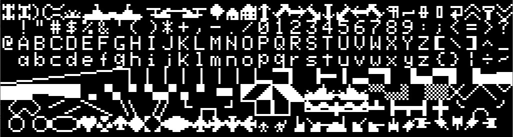
You will notice that in addition the the expected alpha, numeric, and special characters, the ROM contains a large number of character "graphics" to be used in games. This helps to compensate for the lack of a true graphics mode on a stock 4P.
I used PyGame tools to create a display window, and employed the character ROM images to map the contents of the Challenger 4P's shared video memory to that window. I only update the screen character image when the corresponding character in the shared video memory changes to improve performance.
So with the virtual display implement when I start the emulator this is what I see.
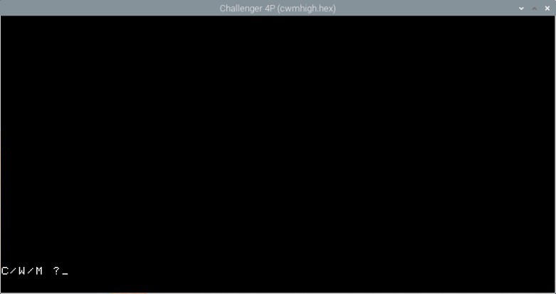
Further proof that the emulator is working as expected but pretty useless without being able to type stuff in.
A Virtual Keyboard
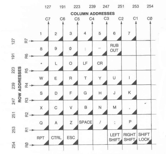
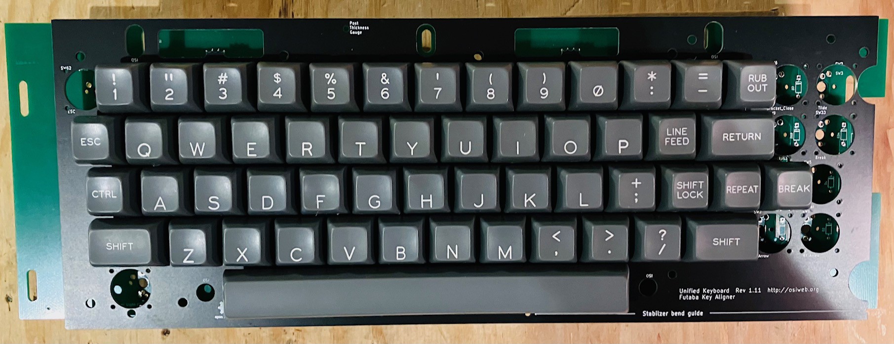
The keyboard on the Challenger 4P is a simple 8 x 8 matrix of switches that looks like this:
How does it work? From the C4P Manual:
Normally, when a program is not executing, a polling routine constantly scans each of the eight rows in succession to determine the column of any key depressed. If a key closure is detected, the polling routine supplies the ASCII code corresponding to the face of the key depressed. During the execution of a program this polling routine is disabled and replaced by a second routine which monitors the <CONTROL> and <C> keys. If these keys are simultaneously depressed, then execution of the program is terminated.
The physical keyboard is mapped to an I/O port at address 0xDF00. For each row, the polling routine will first write to 0xDF00 the number of the row to be checked, then immediately read from 0xDF00 to fetch any key closure columns. The results from all rows will be combined before the ASCII key code is determined.
So for example say that the 2 key is pressed. When the polling routine checks row 7 of the matrix by writing 127 (0x7F or in binary 01111111 - note that the 0 bit indicates the row to query) to 0xDF00, when 0xDF00 is subsequently read the value 191 (0xBF or binary 10111111) is returned indicating that a key at column 6 (the one with the 0) has been pressed. When finished all 8 rows, assuming no other keys are pressed, the polling routine knows enough return the ASCII value for 2. Furthermore if the Shift key is also pressed at the same time as the 2 key, then the combined column value will be 189 (0xBD or binary 10111101) indicating that the 2 key and the Right Shift key were pressed at the same time and the polling routine would return the ASCII value for ".
For my virtual keyboard I have to convert the ASCII values that I get from the PyGame keyboard interface to the appropriate column results that the C4P polling routine is expecting (so they can be converted back to ASCII ;-) To accomplish this I have a table that looks something like this:
| Unshifted Character | Shifted Character | Matrix Row | Matrix Column |
|---|---|---|---|
| 1 | ! | 7 | 7 |
| 2 | " | 7 | 6 |
| 3 | # | 7 | 5 |
| 4 | $ | 7 | 4 |
| 5 | % | 7 | 3 |
| 6 | & | 7 | 2 |
| 7 | \ | 7 | 1 |
| 8 | ( | 6 | 7 |
| 9 | ) | 6 | 6 |
| 0 | @ | 6 | 5 |
| ETC... |
My emulator monitors reads and writes to 0xDF00 and simulates the behavior of the Challenge 4P hardware using this table to formulate the proper responses. None of this will be necessary when I get Dave's Unified Retro Keyboard and OSI interface board which has the latches required for scanning the OSI key matrix, and an OSI compatible 16-pin connector.
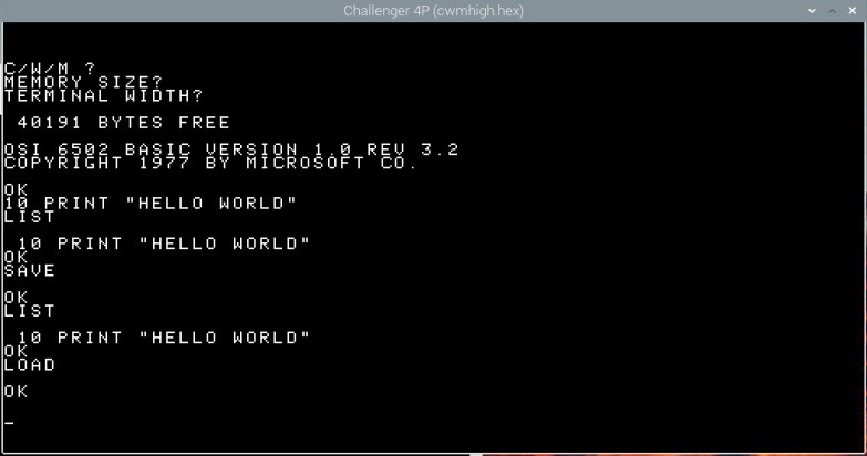
So now with a working keyboard we can do a little more interesting stuff with the emulator.
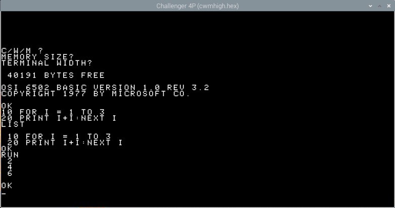
Cool.
A Virtual Cassette
So being able to key in and run BASIC programs is great and all, but you wouldn't want to do it for programs more than a few lines of code. For that reason the Challenger 4P and many of it's contemporaries had a cassette interface. You could connect a relatively inexpensive cassette deck to the computer and save/load your work to/from tape. At the time floppy diskettes and hard drives were also available, but in those early days were very expensive.
To save a BASIC program that you have typed in to cassette tape, you would (from the C4P Manual):
- Type SAVE <Return>
- Type NULL8 <Return> (NOTE: Not necessary for a virtual cassette.)
- Type LIST but do not press <Return> yet.
- Turn on the tape recorder in the RECORD mode. When the tape (dark brown) begins to wind onto the right-hand spool, wait 5 seconds, then press <Return>
- Wait until the entire program has been listed to the screen (and saved to cassette), wait a few more seconds, then turn off the recorder.
- To reset the computer to keyboard input type in LOAD <Return>
- Press <Space> followed by <Return>
Similarly for loading a BASIC program:
- Rewind the cassette until the clear tape leader is visible.
- Type NEW <Return> to clear the BASIC workspace.
- Type LOAD but do not press <Return> yet.
- Turn on the tape recorder to play the tape. When the tape (dark brown) begins to wind onto the right-hand spool press <Return>
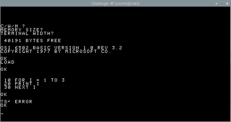
- When the program loading is complete you should see OK, ?S⅃ ERROR, OK on the screen. Turn the tape recorder off.
- To complete the loading of the program press <Space> followed by <Return>
Like the keyboard, the cassette interface is mapped to a couple of I/O ports at addresses 0xF000 and 0xF001. Reading port 0xF000 returns the cassette status as a byte. If the 1's (rightmost) bit is set to 1 it means that a byte is ready to be read from the cassette. If the 2's (second from the right) bit is set to 1 it means that the cassette is ready to write a byte to tape. Reading port 0xF001 will fetch the next byte from the cassette tape. Writing to port 0xF001 will save the byte passed to the cassette tape.
For my virtual cassette implementation, BASIC programs are saved and loaded from disk instead of cassette. By convention these files have a .BAS extension, but are just in fact text files with a listing of the BASIC program. The files are located in the TAPEs subfolder.
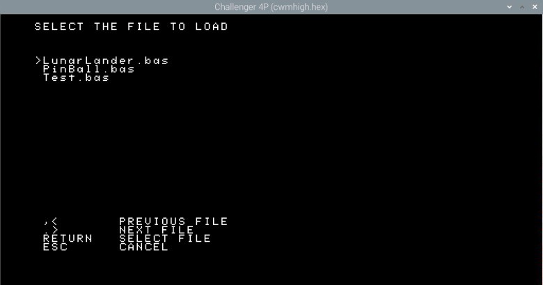
To load a virtual cassette, follow the steps as outlined above except that for step 4:
4. Press CTRL-L to bring up the load dialog, select the BASIC program to load using the < and > keys, then press <Return>.
The screen supports a scrolling list of any number of file names. The files listed must be located in the TAPEs folder and only files with a .bas extension will be shown.
Finish the load steps. When done you should then see:
Similarly to save to a virtual cassette file, follow the steps as outlined above except that for step 4:
4. Press CTRL-S to bring up the save as dialog, enter the BASIC program name to save to, then press <Return>.
Simply type the file name in and press Return. If the user does not add a .bas extension one will be added on their behalf since only BASIC files can be loaded or saved. There is an additional check to see if the file name entered already exists. If it does:
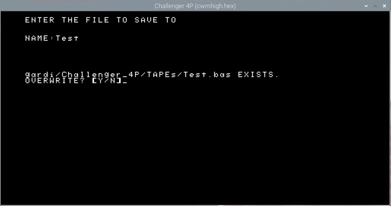
Only pressing the 'Y' or "y" key will allow overwriting. Any other key and the user will have to start over.
Finish the rest of the save steps and you should see:
And that is pretty much it for the emulator. Now it's time to look at the hardware.
Keyboard Assembly
The Keyboard
When the keyboard PCB, a set of Fubata MD-4PCS keys, a stabilizer panel for the Fubata keys, and a set of reproduction OSI keycaps arrived from Dave at osiweb.org I proceeded to assembled the keyboard. I'm not going to detail the process here since it was mostly identical to the work I did on my Sol-20 Reproduction. For details check out:
- Keyboard Construction (Note that the newer keyboard PCB has the discrete diodes and resistors pre-populated on the board. A real time saver. Thanks Dave.)
After adding the OSI Challenger style keycaps this is what I have.
The Encoder
I also assembled one of Dave's classic keyboard encoders. Ultimately I will be using a new OSI specific encoder that Dave is still working on, but for now the classic will do the job. Again you can see details from my Sol-20 Reproduction. Check out:
Here is what the end result looks like.
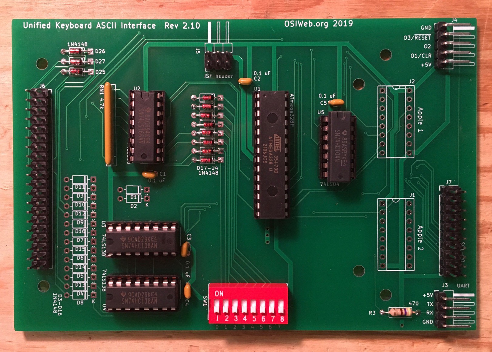
The assembly was all pretty straight forward. Nothing to see here.
Building the Case
When you don't have an original to work from, it is often difficult to create a reproduction. There are usually lots of photos available online, but they don't give any indication of the case dimensions. Often I am helped by enthusiasts that own an original and are kind enough to share some measurements and photos with me.
Fortunately for me there is a robust Ohio Scientific community out there. A great place to start is Dave's OSI Page. This was an invaluable resource when I was creating the 4P emulator. For the case, Dave himself pointed me at a thread in the OSI Discussion Forum where a participant name Steve Gray posted all of the very measurements I was looking for. Using Steve's measurements I modeled some case parts.
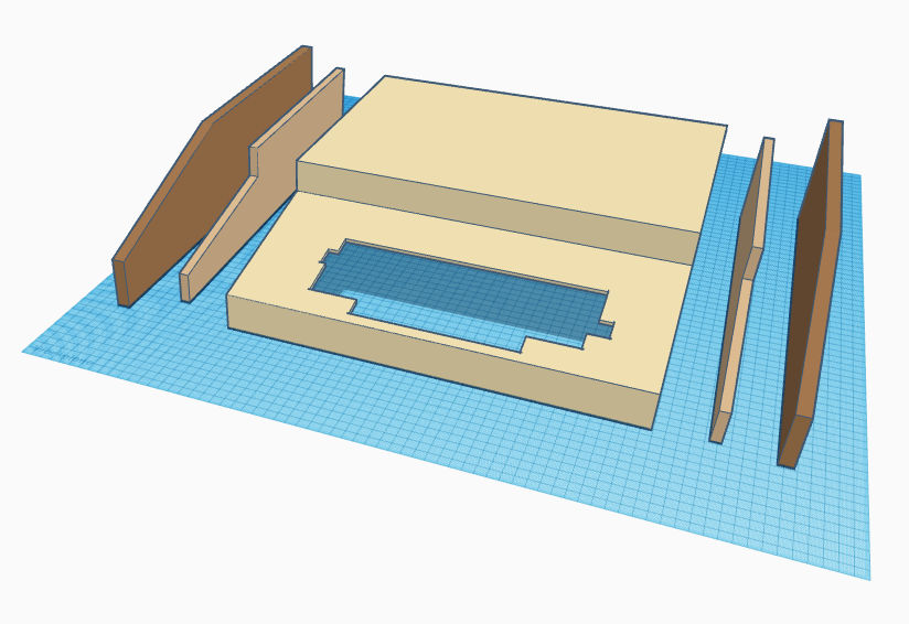
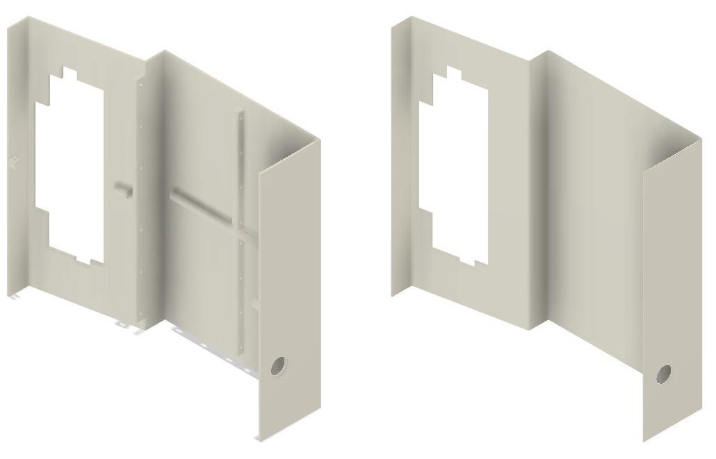
I used the models based on Steve's measurements to create a DXF file to cut out the side panels.
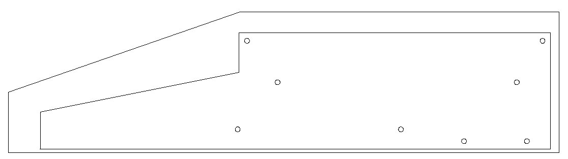
The inside panel has holes defined that will be used to join the inside panels to the cross-bars that will separate them at the correct distance apart, and there are also holes to connect the outside panels to the inside panels. Using 1/8 inch plywood I laser cut one piece exactly as above with the inside panel nested within the outside (thanks kwartzlab), then I cut three more inside panels only.
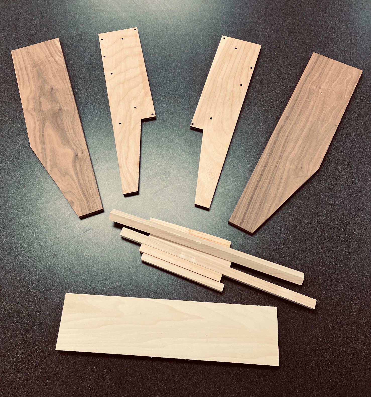
I glued pairs of inside panels together so I had two 1/4 inch inside panels. I then used the outside cut panel as a template to layout the two outside panels on a nice plank of 1/2 inch walnut. These I cut out with skill and jig saws and used a belt sander to smooth the edges.
Finally I cut out some cross-pieces 364 mm long. One was 1/2 x 4 inch pine, plus two 5/8 inch square dowels. In addition I cut four 130 mm lengths of 1/2 inch dowel.
So here is was I ended up with.
I attached the cross-pieces to the insides with #6 - 1 inch wood screws making sure the the heads were flush with the panel. The shorter 1/2 inch dowels were doubled up attached to the inside of the side panels at 20 mm below the slanted edge to support the keyboard.
Finally I used the outside template to properly align the inside pieces to the outside and joined them with 5/8 inch wood screws.
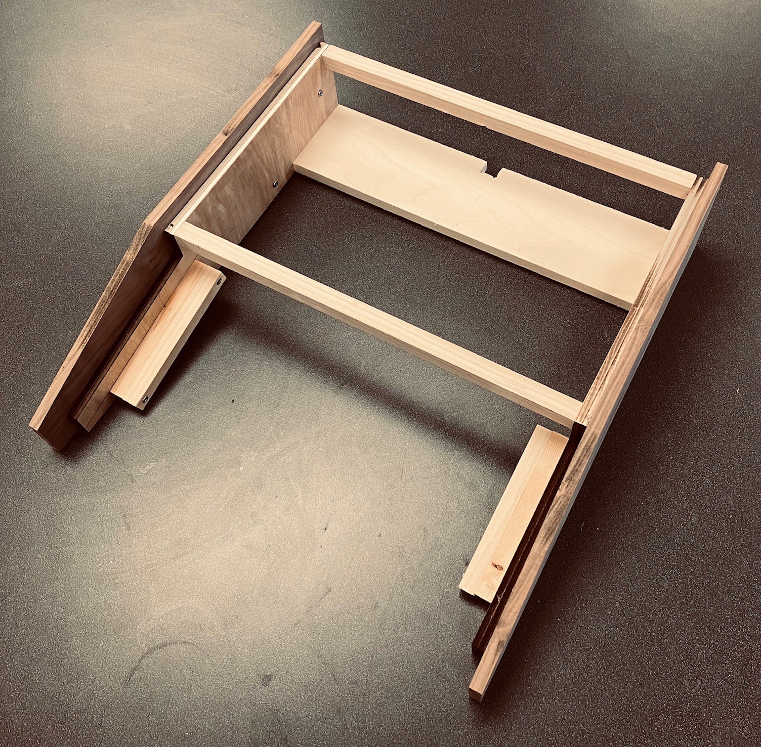
Also notice that I cut a 10 x 10 mm notch into the back of the 1/2 x 4 inch cross-bar to accommodate a support beam on the case.
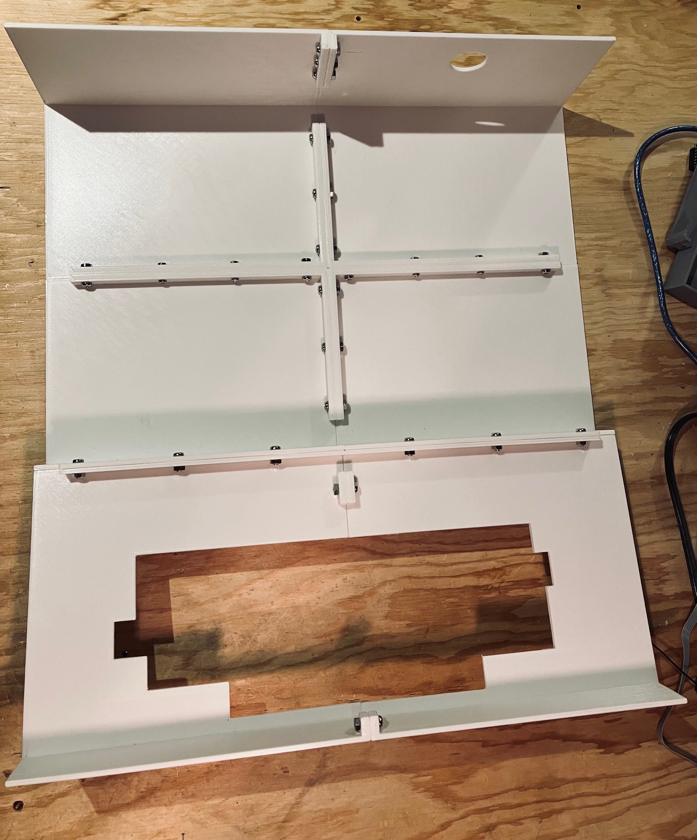
I printed the case as six separate pieces that are small enough to fit on my print bed. To facilitate the reconstruction I have added support beams underneath with holes so I can bolt the separate pieces back together again.
All together the parts took about 50 hours to print. The case parts printed well. There were a couple of places where the print pulled up a tiny little bit in the corners, despite a 10 mm brim, but not very noticeably. I joined the pieces to together with M4 x 12 mm bolts and nuts.
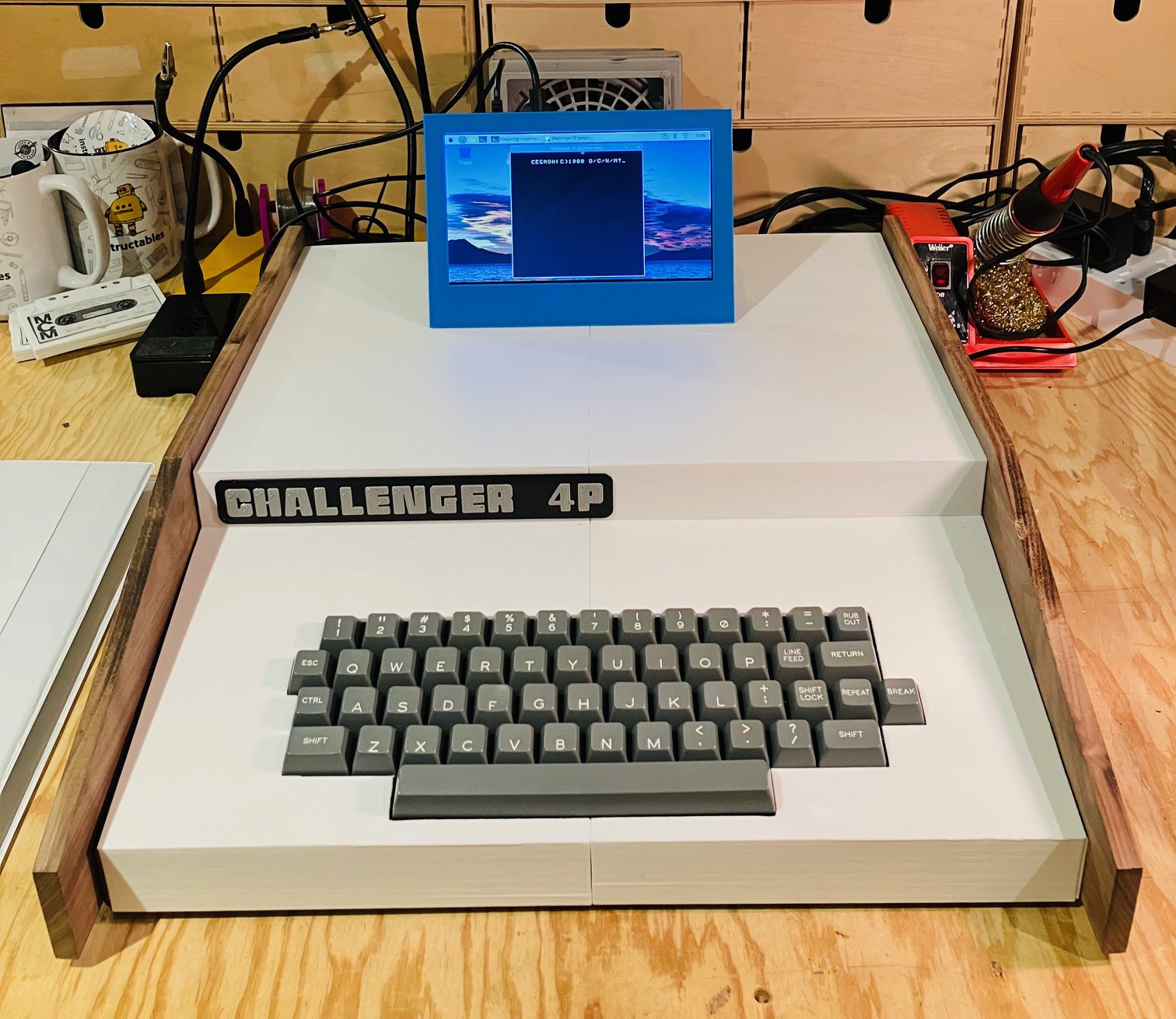
Then I fitted "skin" onto the frame. With the skin on I was able to adjust the keyboard to fit inside of the cutout and screw it down. To Steve's credit (the measurer) and Dave's (the keyboard maker) it fit perfectly. All I had to do then is 3D print a logo and voila!
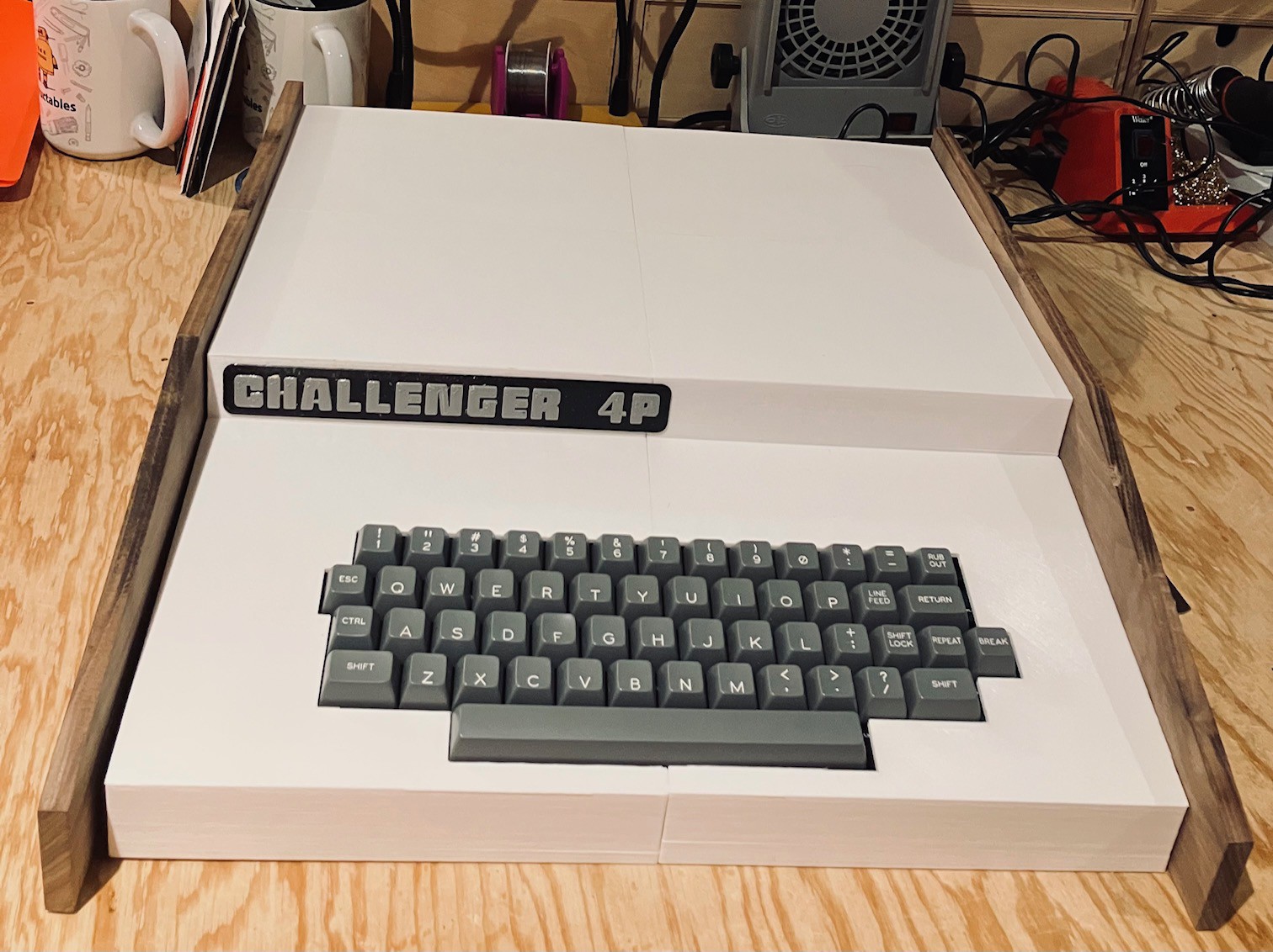
Even though not necessary, for authenticity I thought about adding the 14 or so screws that can be seen on the top of the original's case, but in the end decided that I liked the cleaner look of what I have.
Preparing the Pi
So far, all of the Challenger 4P emulation development has been done on my Windows laptop using LiClipse. LiClipse is an extension of the Eclipse development environment. I used Eclipse for the last 25 years of my software development career so I'm familiar with it, and chose the LiClipse variant because it came bundled with PyDev, a Python IDE for Eclipse.
Now it's time to move the emulator to the Raspberry Pi 4 that will power my Challenger 4P reproduction. One of the reasons that I chose Python for this project was this portability. When I started this project over a year ago, I had hoped that the supply issues which made Pi 4s virtually unobtainable would have been fixed. No such luck. I looks like Pi 4s will not reach unconstrained availability until Q3 2023. Sigh. Fortunately one of my mates at the local makerspace (Kwartzlab) had one to spare that I could use until such time as I can buy one for myself.
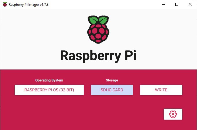
I'm not going to detail getting the Raspberry Pi OS onto the Pi 4 as there are a lot of guides out there like this one from tom'sHARDWARE. Basically I just loaded a Raspberry Pi OS image onto a 32 Gb microSD card using Raspberry Pi Imager.
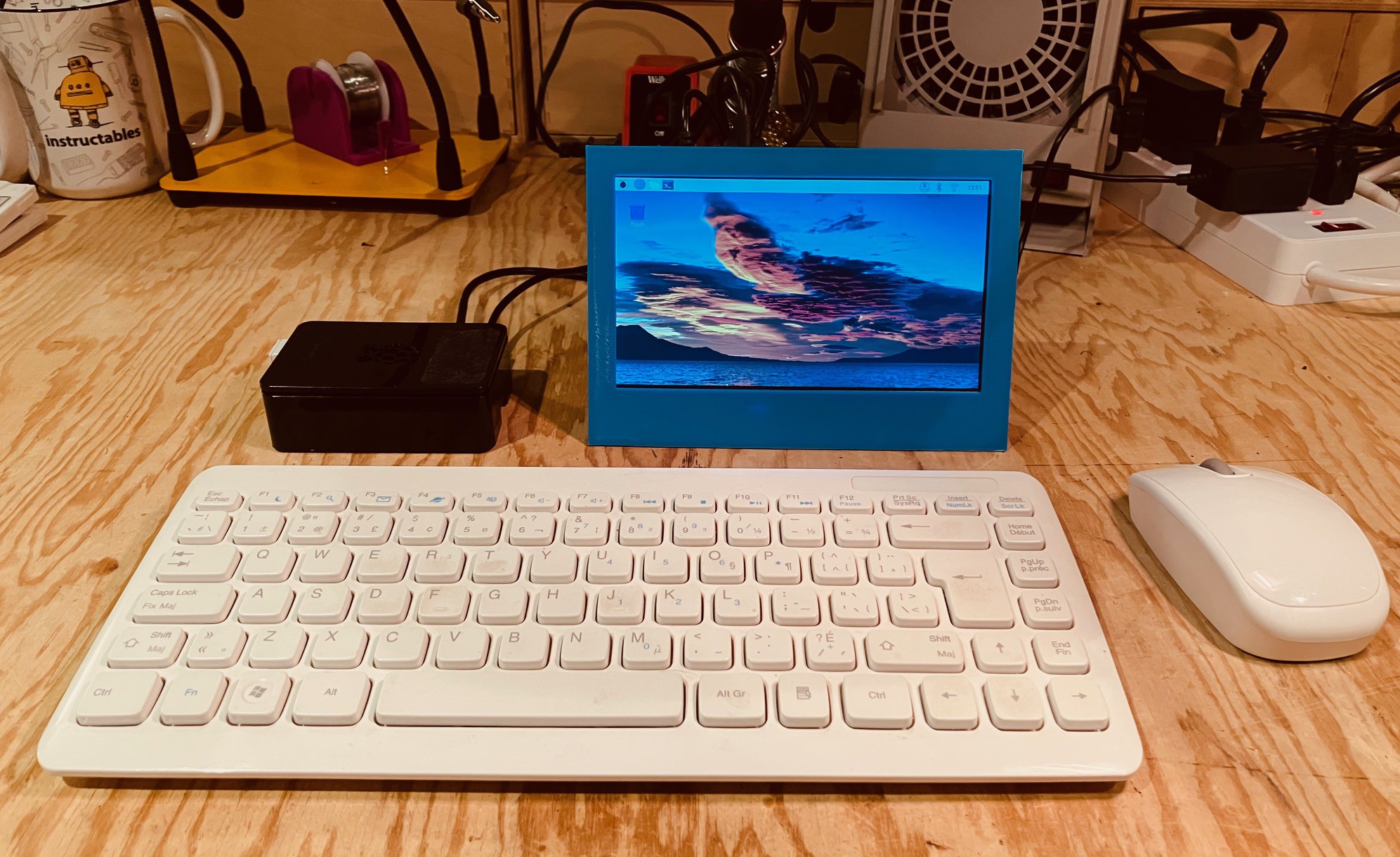
I plugged the microSD card into the Pi 4 to which I had attached a small LCD screen, wireless mouse, and keyboard. You could do the installation completely "headless" as outlined here, but I prefer to do the configuration interactively with this the setup. I powered up the Pi and went through the initial configuration dialogs to set the login user, keyboard, language, locale, and wireless connection. Super easy.
Ultimately the Pi will be run headless with no keyboard or mouse. There will however be a display to show the emulator's screen. My preference is to use VNC to accomplish this. Raspberry Pi OS ships with RealVNC pre-installed. So the first thing that I did after the basic OS had been installed was to setup a virtual server for the RealVNC client to connect to. The easiest way I have found to do this is to add the following lines to the end of the /etc/rc.local file before the exit 0 on the Pi.
# Setup a virtual screen for the VNC server.
sudo -u xxxxx vncserver -randr=1920x1080
xxxxx is the login user that you setup to access the Raspberry Pi. Set the screen dimension (randr=) to be the same as that of the machine’s display that you will be accessing the Challenger 4P from.
I found in my setup is that there were a few issues accessing this server with the RealVNC client on my Windows machine. The first was that the menu bar at the top of the desktop was missing. To restore the desktop menu bar enter the following command.
sudo apt-get remove --purge alsa-base pulseaudio
On a similar note the title bar on open application windows and the corresponding windows controls (v ^ x) were missing as well. To fix this I edited the desktop.conf file,
sudo nano /etc/xdg/lxsession/LXDE-pi/desktop.conf
and changed the line:
window_manager=mutter to window_manager=openbox-lxde-pi
then saved the changes.
With these changes made reboot the Pi 4 for them to take effect.
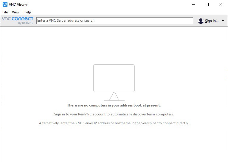
I downloaded and installed the RealVNC client on my Windows machine. Run the RealVNC VNC Viewer. You should see this window.
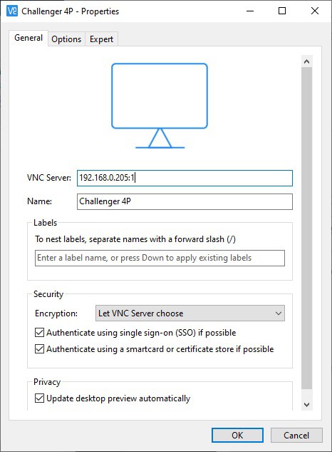
From the menu select File->New connection... to bring up the following dialog. Add the Server address and common name then click OK. Note the :1 added to the server address. This references the instance of the VCN Server running.
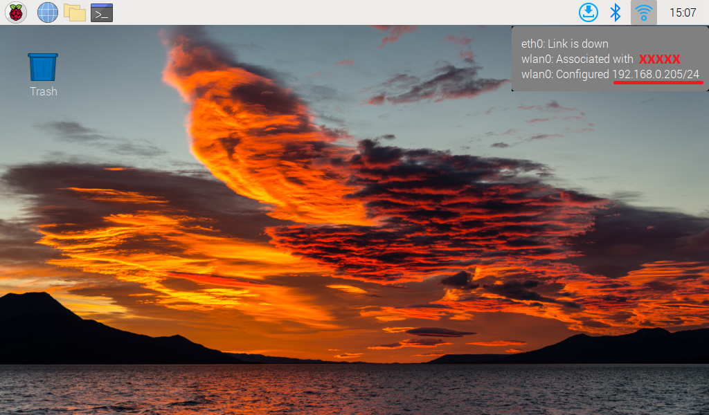
To find the VNC Server address you can just hover over the WiFi (or network) connection on the server desktop.
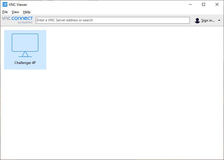
From the main VNC Viewer window double click on the Challenger 4P connection just created.
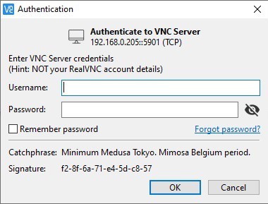
The first time you attempt a connection you will be prompted to enter the Raspberry Pi's login credentials. Check Remember password if you don't want to have to do this every time you connect. Enter the credentials and click OK.
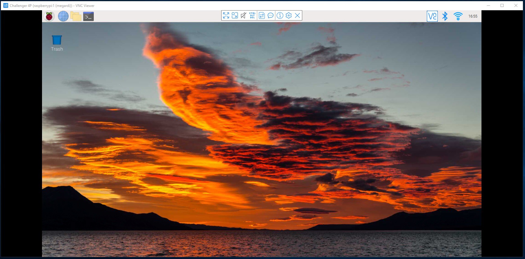
You should see an instance of the Pi 4's desktop.
To get the emulator onto the Pi 4 you can simply clone the repository from github. Open a terminal window and enter the following command:
git clone https://github.com/kidmirage/OSI-Challenger-1P-Reproduction
You should see a response similar to this:
Cloning into 'OSI-Challenger-1P-Reproduction'... remote: Enumerating objects: 70, done. remote: Counting objects: 100% (3/3), done. remote: Compressing objects: 100% (3/3), done. remote: Total 70 (delta 0), reused 0 (delta 0), pack-reused 67 Receiving objects: 100% (70/70), 67.60 KiB | 1.04 MiB/s, done. Resolving deltas: 100% (28/28), done.
To run the emulator run the following commands:
cd OSI-Challenger-1P-Reproduction/
python3 main.py
You should see the Challenger 4P emulator popup.
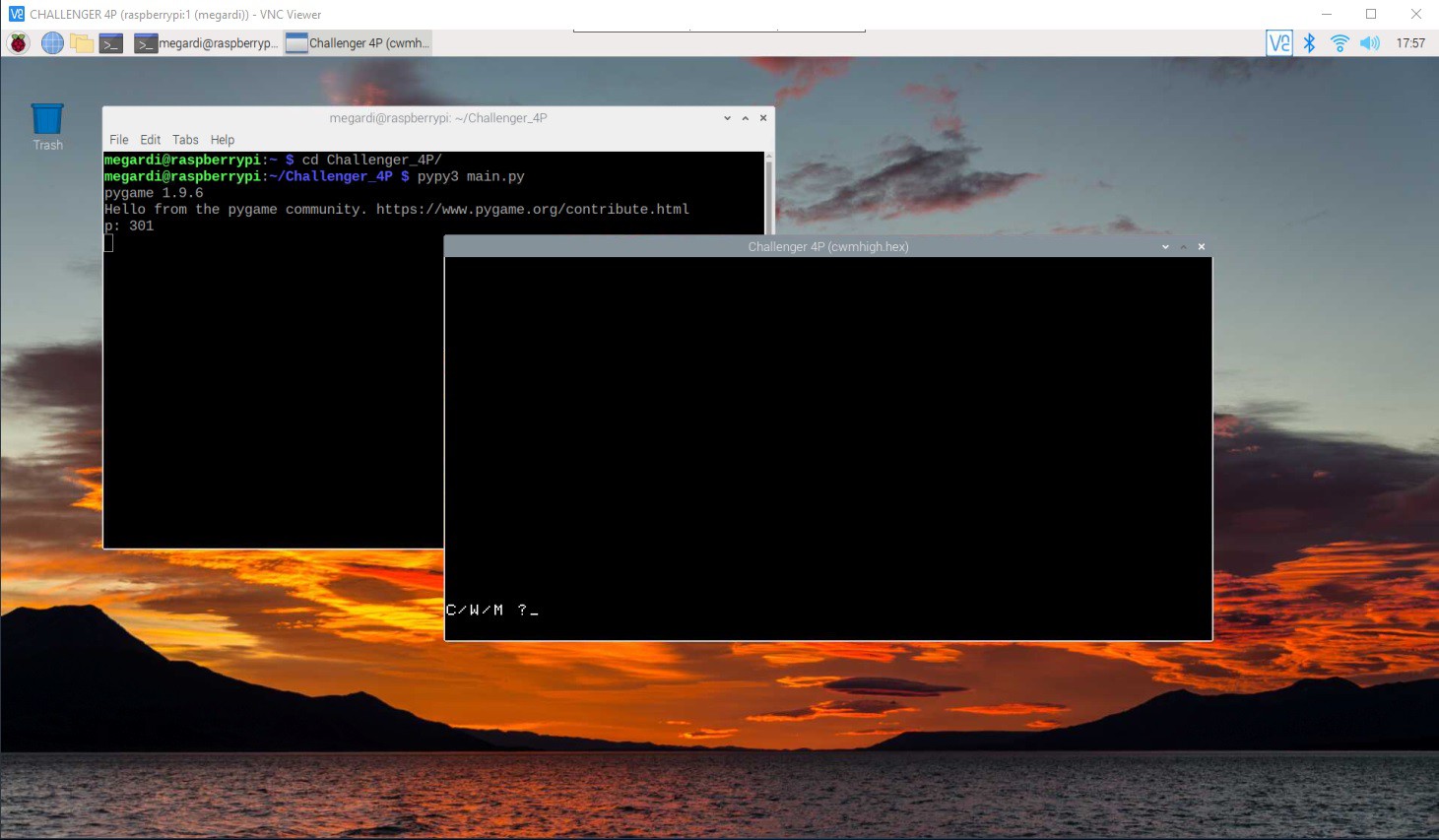
I noticed that there was a problem with the emulator. The keyboard was not working correctly with shifted keys. It turned out to be an issue with the way that I implemented the keyboard handler and the version of PyGame that came pre-installed on the Raspberry Pi OS distribution. This was fixed by updating PyGame with the following command.
pip install pygame --upgrade
After doing some testing I discovered that the emulator under python3.11 ran at about twice the speed as under python3.9 (which was the default pre-installed on the Raspberry Pi OS). Furthermore if you use pypy3.9 the emulator runs about four times faster. So of course I am using pypy.
cd OSI-Challenger-1P-Reproduction/
pypy3 main.py
Systems Integration
Well the case is done, the keyboard is assembled, and the Challenger 4P emulator is running on the Raspberry Pi 4. I guess it's time integrate all the pieces. To that end the only real task is to wire the keyboard to the Pi and write the emulator Python code to read the hardware keyboard keys.
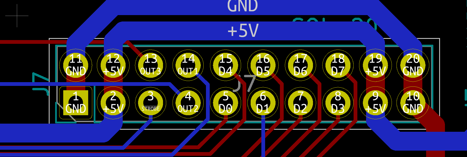
We are ready to wire the keyboard to the Pi. I'm using the header on the encoder labeled SOL-20. The pinout looks like this.
The keyboard encoder is expecting 5V while the Raspberry Pi 4 operates at 3.3V. So to overcome this I purchase a Voltage-Level Shifter Module from Amazon.

Here is how I wired the keyboard. Note that for the exception of +5V and GND lines which are wired to the 3.3V side or the level shifter, all of the other connections are wired to the 5V side.
| Keyboard Encoder | Raspberry Pi | Description |
|---|---|---|
| 5V | 5V | Power |
| GND | GND | Ground |
| D0 | GPIO5 | Key 0 bit (low) |
| D1 | GPIO6 | Key 1 bit |
| D2 | GPIO12 | Key 2 bit |
| D3 | GPIO13 | Key 3 bit |
| D4 | GPIO19 | Key 4 bit |
| D5 | GPIO16 | Key 5 bit |
| D6 | GPIO26 | Key 6 bit |
| D7 | GPIO20 | Key 7 bit (high) |
| STROBE | GPIO4 | Key ready on falling edge. |
Once the wiring was complete I update the emulator's keyboard.py code to detect and process key presses from the keyboard. Note that you can still run the emulator without attaching the "special" keyboard and just use the PC's keyboard. I have posted the updated keyboard.py file to github.
Here is what my little integration test looks like.
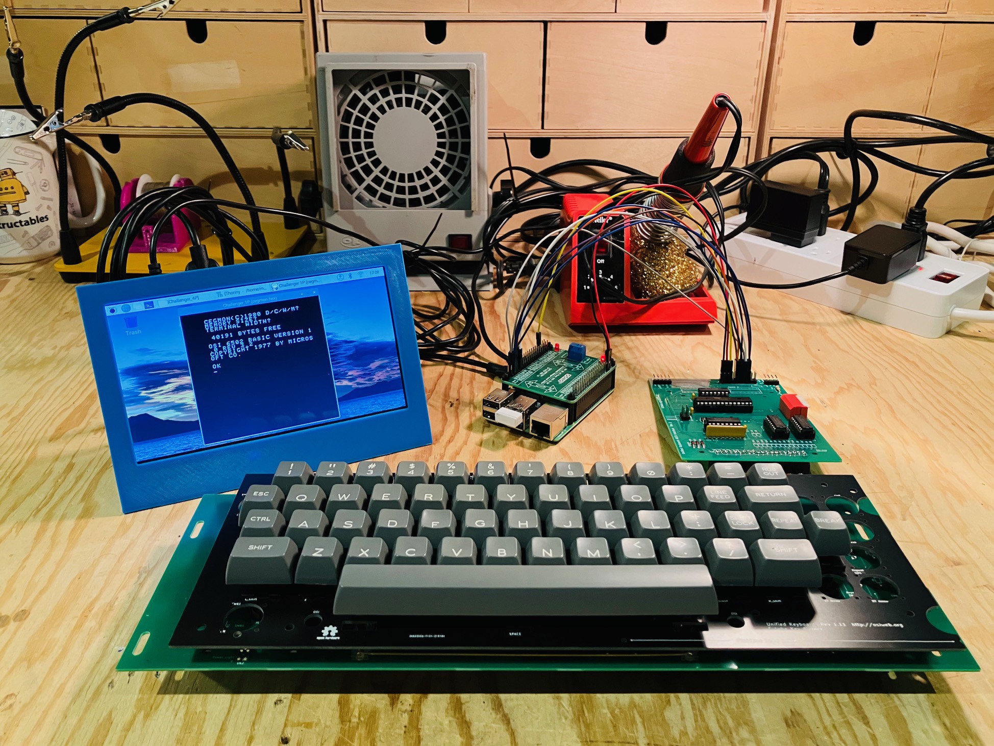
The emulator can be seen running on the small LCD screen. Keyboard seems to be working well. Ready now to insert everything into the case.
Final Assembly
The final assembly is pretty straight forward. I remounted the keyboard. I had already tweaked the keyboard location to correspond with the keyboard cutout on the top panel. I attached the keyboard encoder to the 4 inch cross-bar with a couple of #4 - 1/2 inch wood screws making sure that the 40 pin male connector on the encoder lined up with the 40 pin male connector on the underside of the keyboard. I made a 40 pin female to female IDC flat ribbon cable about 280 mm long and connected the encoder to the keyboard.
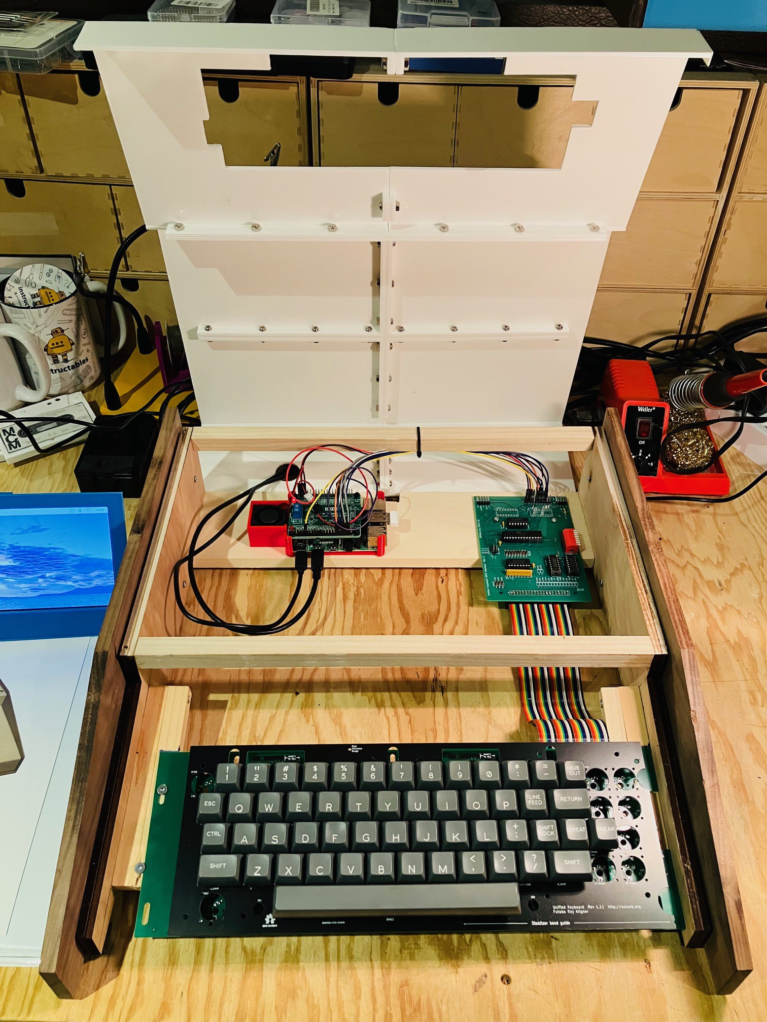
I also printed a "caddy" (red) to hold the Pi 4 in place and added a small 30 mm x 30 mm x 10 mm blower fan for good measure to keep things cool. The fan I used is from Amazon: GDSTIME 3cm 30mm x 10mm 5V DC Brushless Small Blower Cooling Fan, with Dual Ball Bearings. The fan and the keyboard will be run off of the Pi's power supply. The Pi and the caddy are secured in place to with two sided tape.
I ran the Pi power and HDMI cable in through the hole in the back of the case, then dropped the top panel into place.
And that's it.
Adding a Proper Monitor
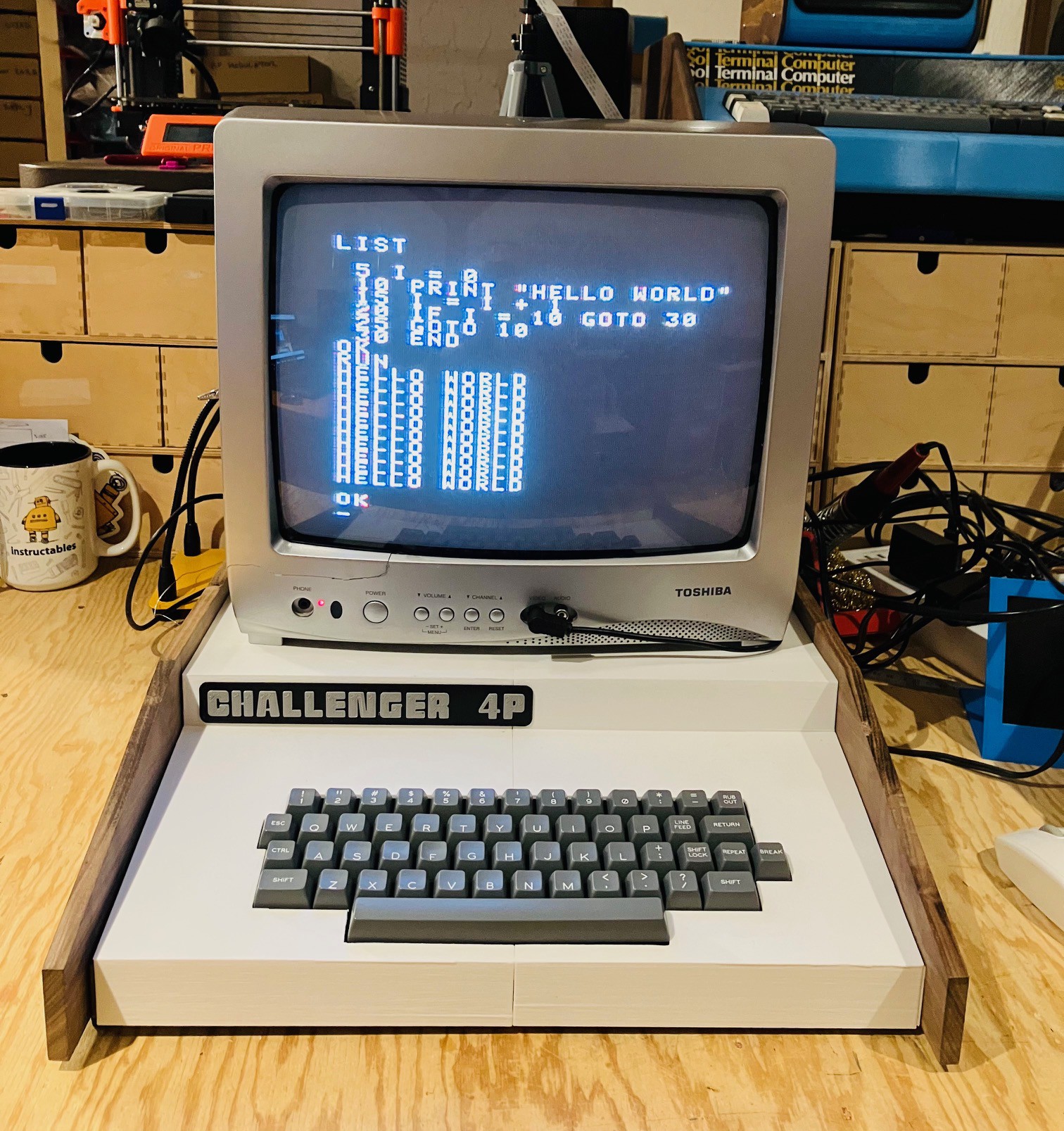
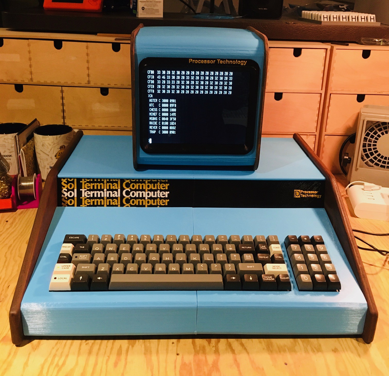
I've been trying to track down a good CRT monitor with a composite input for a while now to pair with some of my recent reproduction projects including the Challenger 4P. All in the name of authenticity. I finally found a Toshiba 13" CRT Color Television Model 13A24. While not from the 70s (more like 2005) it has a nice retro look IMHO. Note in the following picture I am running a Challenger 1P ROM which results in the 25 x 25 display seen below.
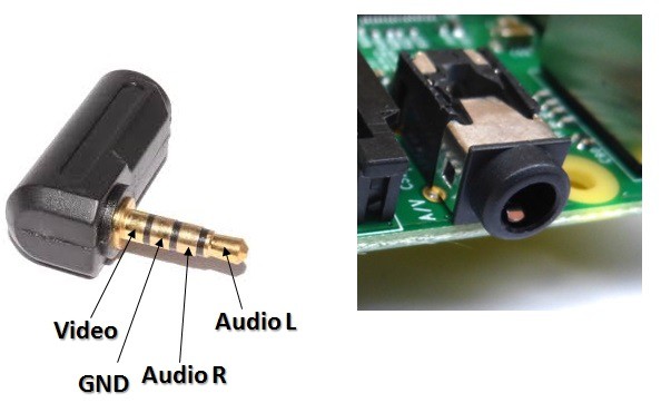
On the Raspberry Pi 4, the composite out signal is on the 3.5 mm jack along with the audio out signals. There are a number of 3.5 mm jack to RCA cables available online, but for the most part they are setup for camcorders. The pinout for the Pi jack is slightly different. Here is the Pi setup.
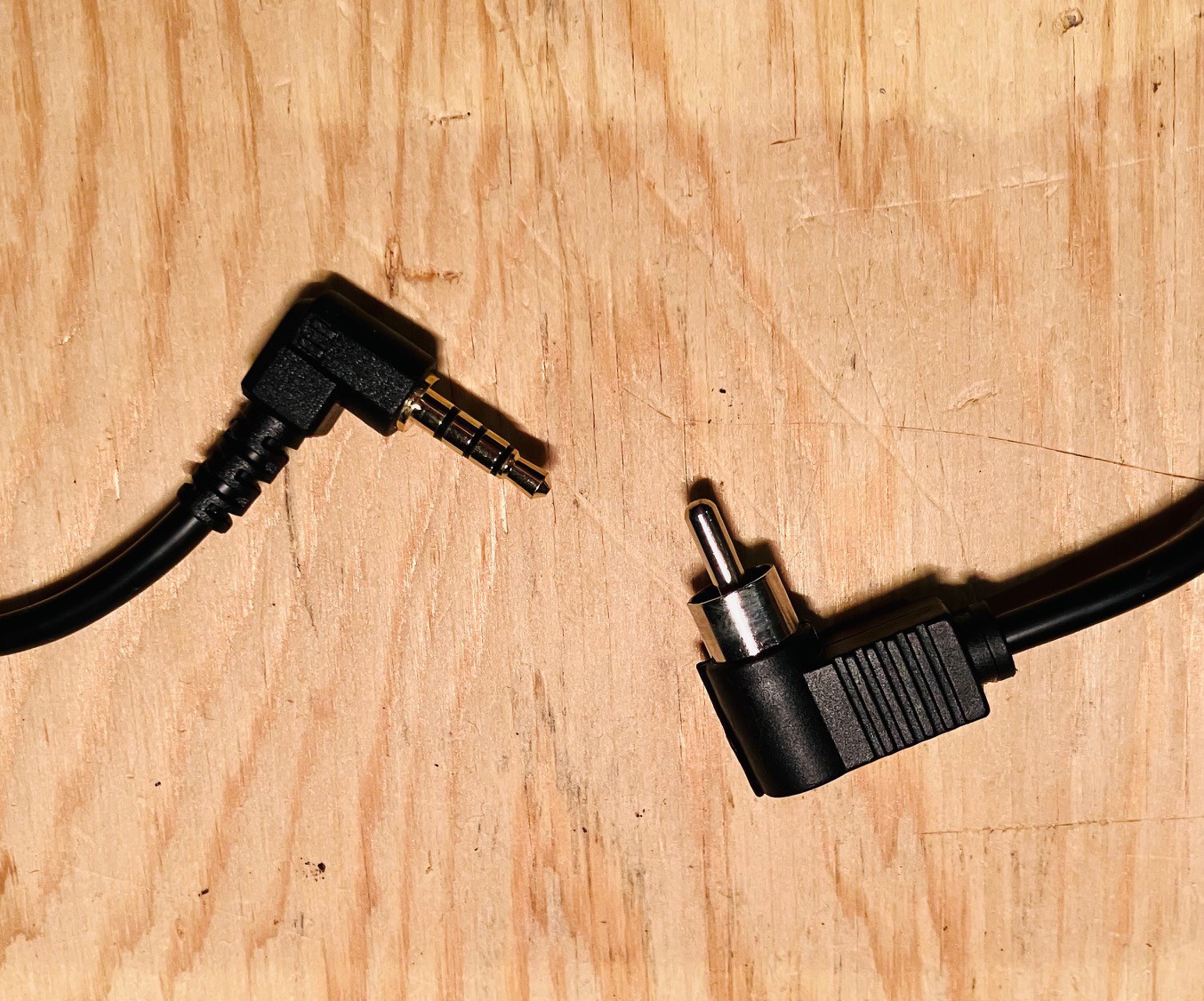
Since I only needed the composite video and no audio I made my own cable with just the one signal plus ground.
To setup for composite out (NTSC in may case) I added and/or changed the following lines in the /boot/config.txt file on the Raspberry Pi.
# setup for NTSC video
sdtv_mode=0
sdtv_aspect=1
enable_tvout=1

dtoverlay=vc4-kms-v3d,composite=1
As can be seen above the TV works great, so far as it goes. I had forgotten how crappy text looks on a composite monitor. While a CRT is much more authentic, the "fake" monitor that I made for my Sol-20 Reproduction, using a period appropriate 4:3 LCD panel, is sure a lot easier on the eyes.
Getting a Second Skin
Every Tuesday night my local makerspace (Kwartzlab) opens up to the public. People can get tours, seek member's advice, or apply for membership. Members come on Tuesdays to catch up with other members or work on their latest projects. I really missed Tuesday Open Night (TON) when we had to suspend them during the height of Covid. Well TON is back baby, better than ever.
At a recent TON, a maker friend told me about a company out of Spain called LaserBoost. They have a process to seamlessly combine laser cutting sheet metal with bending. You only need to submit a single STEP file of your part to get an instant quote. My friend showed me a part they had done with LaserBoost for a Famicom reproduction they are working on. Very cool (the service and the Famicom project). There are a few similar services in the US but after a quick sampling it looks like they are much more expensive.
So I started thinking about my Challenger 4P project. Don't get me wrong, I'm very happy with my 3D printed case top. It's solid (can support the weight of a monitor) and looks good. But I've always wondered how hard it would be to create a more authentic sheet metal skin. Kwartzlab does have tools for bending sheet metal but at this point no equipment for cutting sheet metal. LaserBoost gives me a way to produce a sheet metal skin with minimal effort (not that I am opposed to learning to work more directly with sheet metal at some future date).
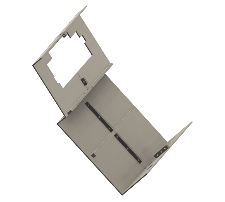
I started with my Fusion 360 3D printed skin model and removed all the braces (mostly just rolling back the Fusion 360 history). Then I reduced the case thickness from 3 mm to 1.2 mm (18 guage).
I saved the modified model as a STEP file which I loaded into the LaserBoost instant quote application. I only had to select the Material that I wanted to use (unfinished carbon steel). The application figured out everything else!
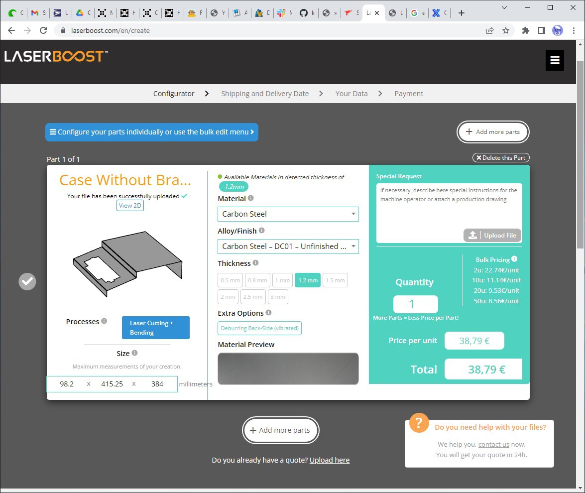
And voila my quote 38,79 € ($41.27 US or $55.77 CAD). In my eyes that is a very reasonable price for a one off, so what's the catch? I did mention that LaserBoost is located in Spain right? It turns out that shipping a largish piece of fabricated sheet metal via DHL (the only international shipping option) is 56,90 € ($60.32 US or $81.81 CAD). Having said this, the quotes I got from the US services that I sampled were so much higher that even free shipping from the US could not offset the cost difference. For instance here is one of the other quotes from a US company which shall not be named.
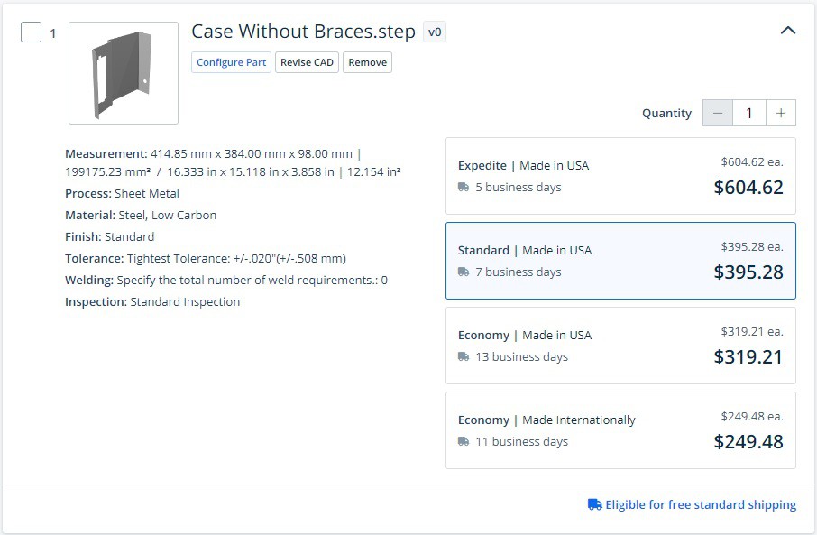
Now I think the quotes are for the same outcome, but I'm new enough at this stuff to have messed up somehow.
At the end of the day I decided to place the order with LaserBoost. With shipping it's a little pricey but I'm anxious to see the result. To get the best price I set 30 day delivery date (like the second quote above, LaserBoost charges extra for "expedited" delivery on a sliding scale).
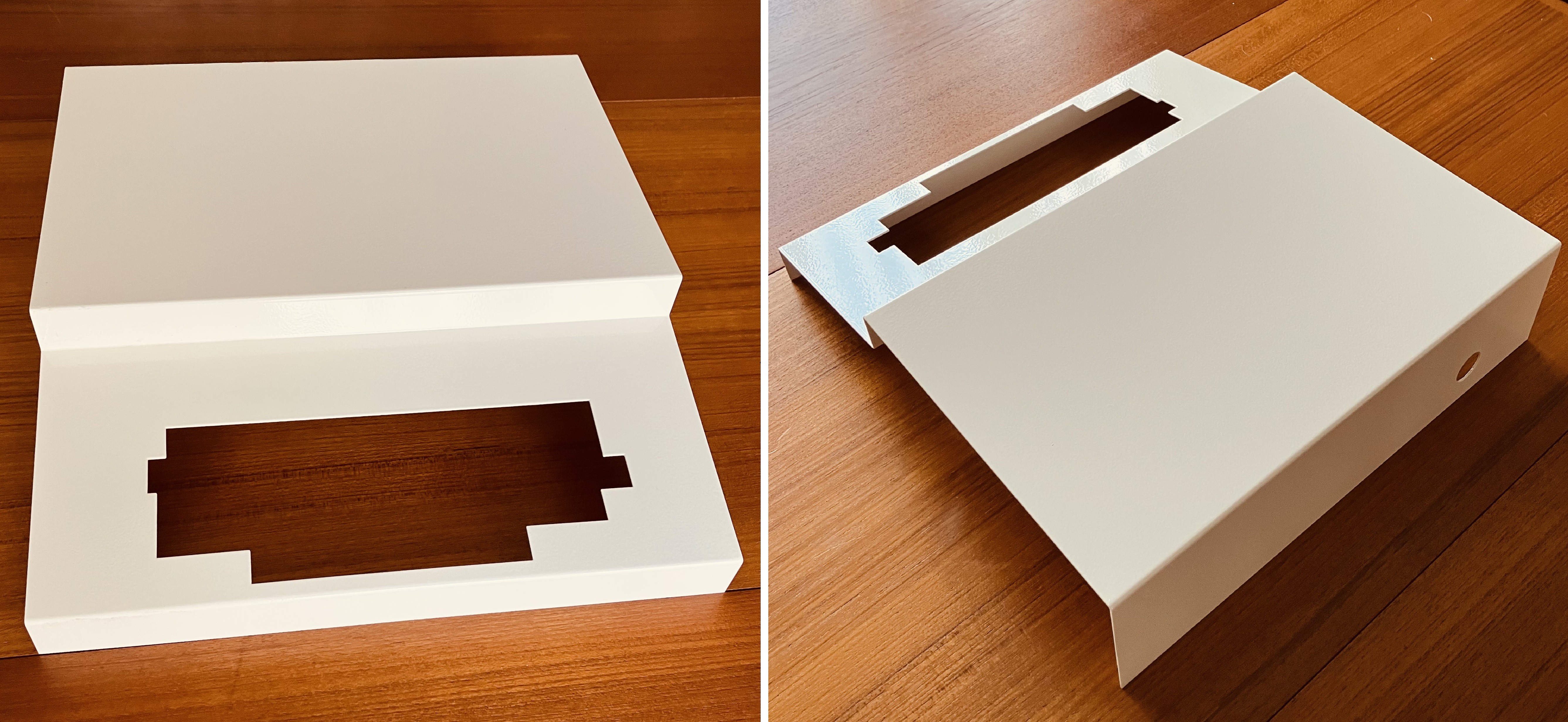
When the fabricated steel top for the Challenger 4P arrived from LASERBOOST I was blown away. Wow. What an incredible job they did.
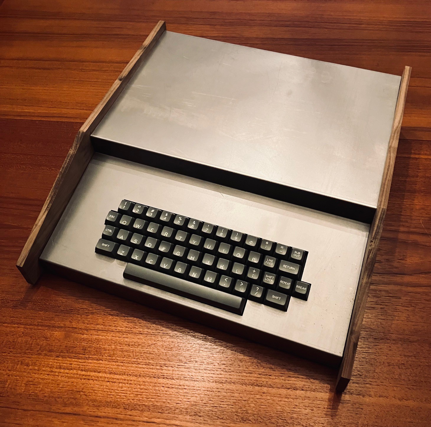
A perfect fit! I decided to have the new cover for my Challenger 4P powder coated at a local shop (Westex Coatings Inc.). Very happy with the result.
With the proliferation of 3D printers, the 3D printed "skins" I have designed for this and my other reproductions, are easily within the reach of a large number of makers. Now, companies like LASERBOOST are making sheet metal fabrication more accessible as well. Even though my reproductions for the most part have emulated "insides", I have always strived to make the exteriors match as closely to the original's as possible. My new sheet metal skin goes a long way towards achieving that authenticity for the Challenger 4P.
Autostart
One of the finishing touches I wanted on this project is to make the Raspberry Pi boot directly into the Challenger CP4 emulator on startup.
I created an autostart folder on my Pi and switched to that folder. Note that megardi is the logon user name for the Pi and will be different for your system.
mkdir /home/megardi/.config/autostart
cd /home/megardi/.config/autostart
Into the autostart folder just created I added the following two files.
runCP4
cd /home/megardi/Challenger_4P
sudo pypy3 main.py
Challenger_4P is the folder where the emulator is installed. For some reason the pigpio library requires root access hence the sudo.
CP4.desktop
[Desktop Entry]
Type=Application Name=CP4
Exec=/home/megardi/.config/autostart/runCP4
In addition the runCP4 file must be made executable with the following command:
sudo chmod 777 runCP4
Final Thoughts
This is the third reproduction in what I have begun to think of as my 70s trilogy series.
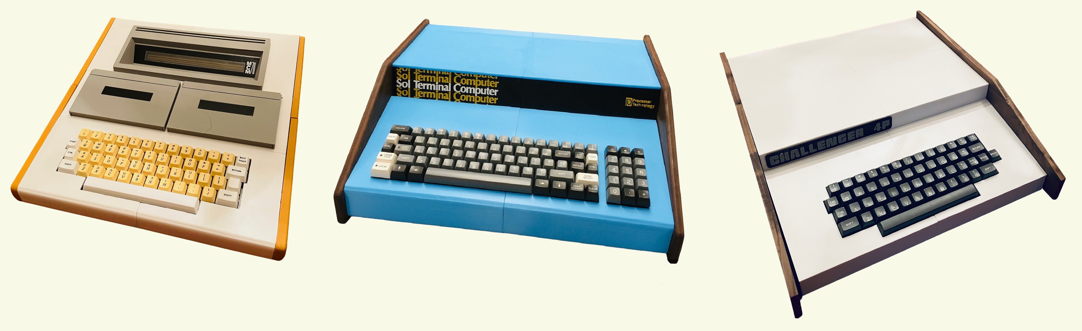
There are many similarities between the three. Obviously they all have roughly the same wedge shape. They could all be considered personal computers because they were portable, had a keyboards and display hardware, a built-in programming language, plus cassette storage capability. Compared to the Apple, Commodore, Tandy, and Sinclair's from the same era they are all relatively obscure.
From and implementation point of view these reproductions are practically identical. The same keyboard and encoder were used for all three, with different layouts and keycaps of course, highlighting the flexibility of Dave's Unified Retrocomputer Keyboard Project. All are powered by a Raspberry Pi 4. The frames all employ similar construction techniques.
But under the covers these three machines are quite different.
| MCM/70 | SOL-20 | Challenger 4P | |
|---|---|---|---|
| Processor | Intel 8008 | Intel 8080 | MOS 6502 |
| Bus | Proprietary | S-100 | S-100 (48-pin) |
| Build In Language | APL | MS BASIC | MS BASIC |
| Cost (US $) | $10,000 | $1630.00 | $698.00 |
| Market | Finance, Military, Education, Government | Personal, Business | Personal, Business |
At the end of the day, most importantly IMHO, while not household names, all three of these machines deserve to be recognized as being an integral part of our shared person computer history.