ElectronicABC
We make an automatic circuit for filling a water tank using BJT and SCR transistors.
Many times I have seen circuits that show a water level but do not control the filling of the tank, that is, when the tank is empty it detects and automatically turns on the motor for filling and when it reaches 100 percent it turns off and the process repeat continuously without the need to do it manually, so design this circuit.
It is very easy to make this circuit since we do not need to understand programming or logic circuits, we just need to understand how a BJT transistor and an SCR work, very basic concepts to be able to do it.
There are many ways to do it either by a level sensor, ultrasonic, floating sensors etc., in this case I will use the floating sensors to detect the 6 levels that we will require.
GERBER PCB:
https://mega.nz/file/6YBxEZqa#yRuZd5PJe8g7YMqE3bYUM7nBtX1fQGd4Rnddu1uDIo8
FLOATING LEVEL SENSOR
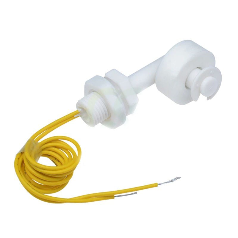
This sensor is very easy, its operation only has 2 states NO and NC, when it is without water its ring will be in the lower part and when water reaches its ring it will begin to float and change its state and it will be NC and close the circuit detecting that it is already there's water.
OPERATION:
We will see the schematic diagram with all its electronic components
The operation is very easy, we turn on the power and we will see that the tank will be empty, the motor will turn on and begin to fill, when it reaches 100% it will turn off and when the water begins to drop below 25% it will turn on again, and so the whole process is repeated automatically.
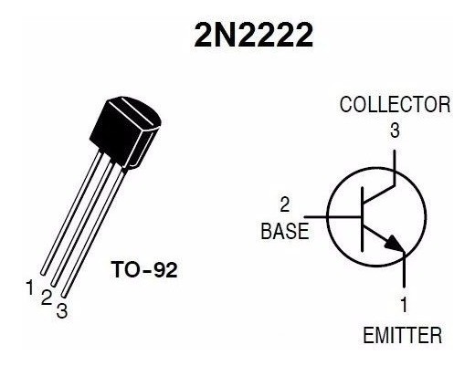
The automation is carried out by the SCR, its operation of this electronic component is easy, when a positive voltage reaches the GATE, its anode and cathode terminals conduct in one direction and remain locked, to deactivate it we will need to cut the power supply between the anode and cathode, then We will use a BJT NPN 2N2222A transistor, thus we will obtain the automation of the project.
SCR:
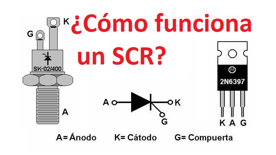
The SCR (Silicon Controlled Rectifier) is a 4-layer semiconductor device that functions as an almost ideal switch.
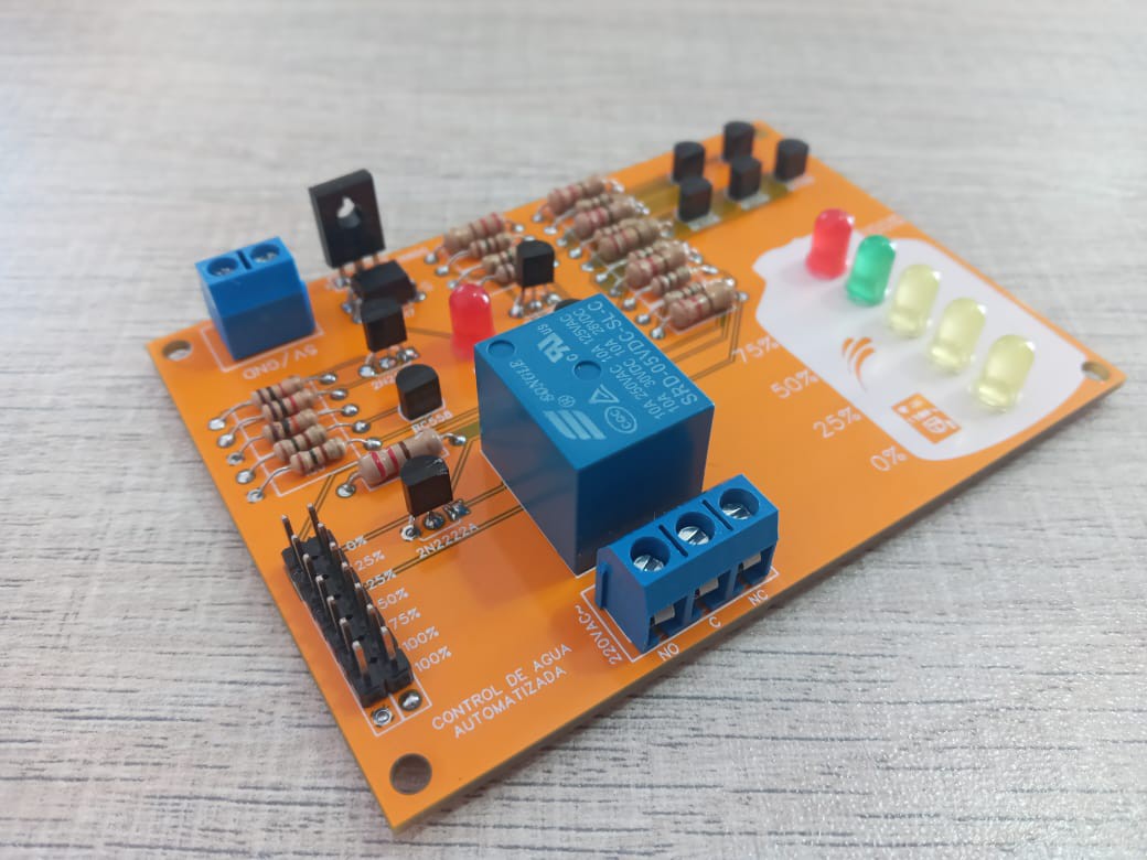
ELECTRONIC COMPONENTS:
7 BC558 TRANSITORS
· 3 TRANSISTORS 2N2222A
· 1 PC817
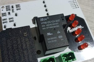
· 1 RELAY 5VDC
· 1 SCR C106DG
· 6 LED DIODES 5MM ANY COLOR
· 3 RESISTORS 1K 1/4W
· 1 RESISTOR 10K 1/4W
· 9 RESISTORS 100 OHM 1/4W
· 7 RESISTORS 220 OHM 1/4W
· 1 BLUE TERMINAL BOARD WITH 2 PINS
· 1 BLUE TERMINAL BOARD WITH 3 PINS
· 2 14-PIN BLADES
· 5 FLOATING LEVEL SENSORS
· 1PCB
CIRCUIT CHARACTERISTICS:
· VIN 5VDC
· 1 RELAY OUTPUT
· OUTPUT CURRENT 10A MAX
· OUTPUT VOLTAGE 220VAC
· AUTOMATED CIRCUIT
· CIRCUIT CURRENT 150mA
PCB DESIGN IN EASY EDA:
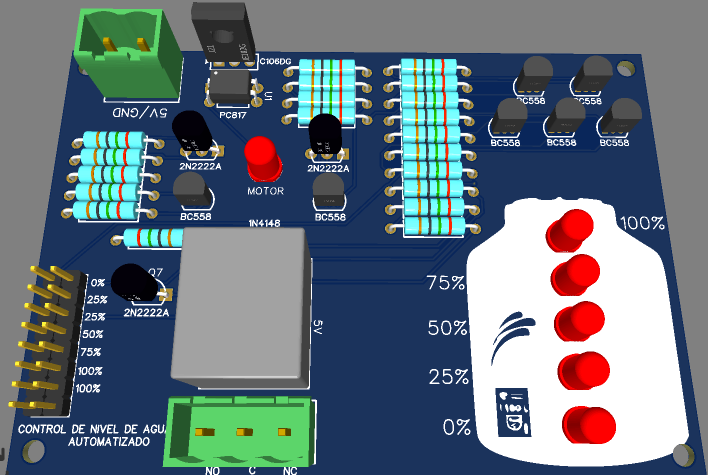
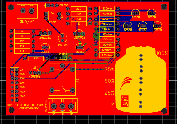
Here we will see the pcb design in the easyeda software and the 3D image of the PCB.
JLCPCB:
Once the pcb is designed, we will send our friends from JLCPCB to manufacture our PCB.
5pcbs only $2
JLCPCB number 1 PCB manufacturing company worldwide professional pcbs and excellent finish.
GERBER...
Read more »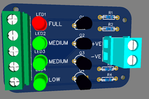
 Mrinnovative
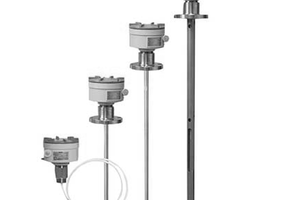
 mbsg99
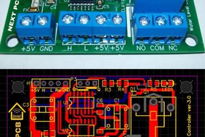
 Technical RC Sharma