0%
0%
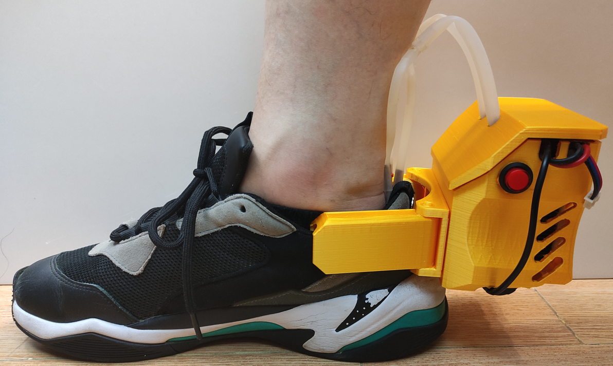
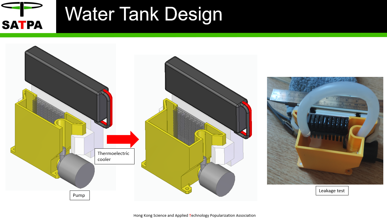
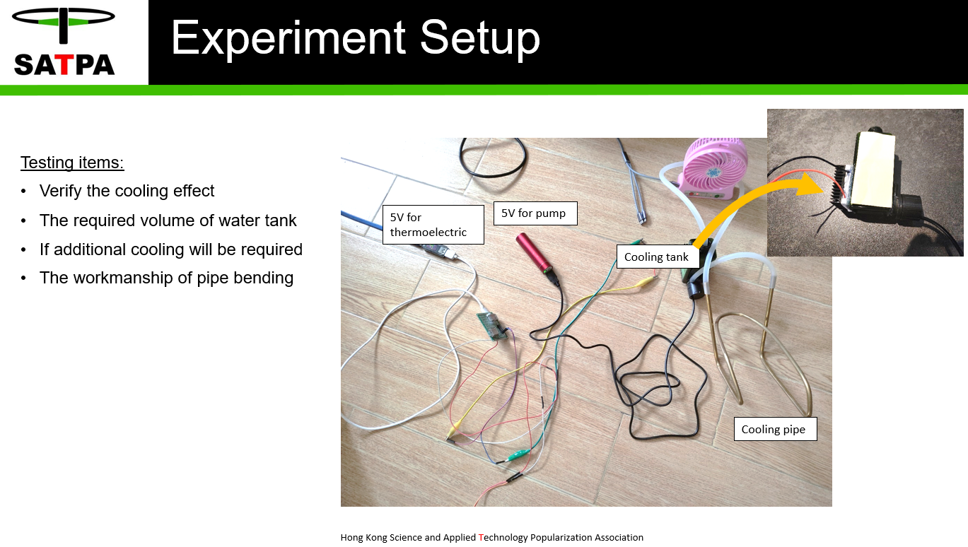
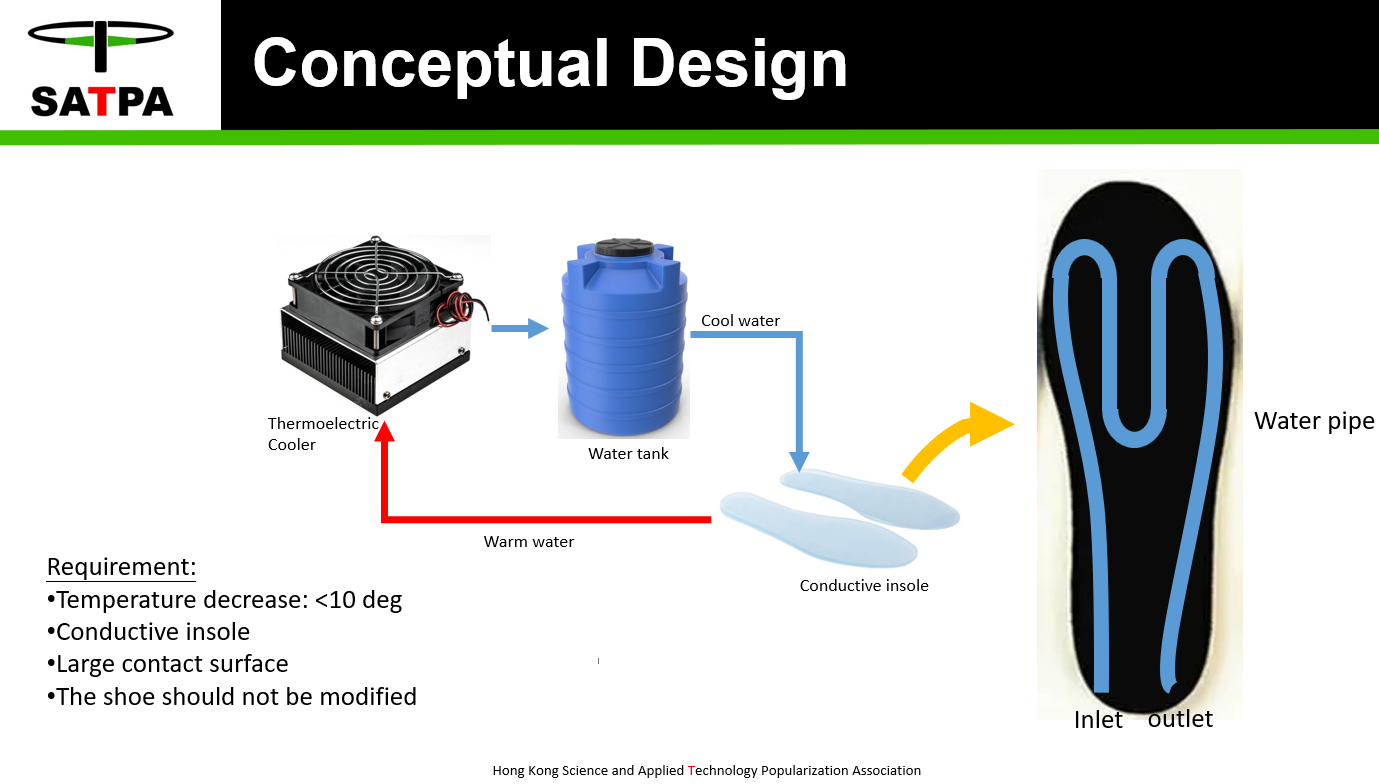
Footwear Cooler
To develop a water cooler to regulate the temperature of the feet or for some people with hot feet problem
 Revoxdyna
Become a Hackaday.io member
Already have an account? Log in.
Just one more thing
To make the experience fit your profile, pick a username and tell us what interests you.
Pick an awesome username
hackaday.io/
Your profile's URL: hackaday.io/username. Max 25 alphanumeric characters.
Pick a few interests
Projects that share your interests
People that share your interests
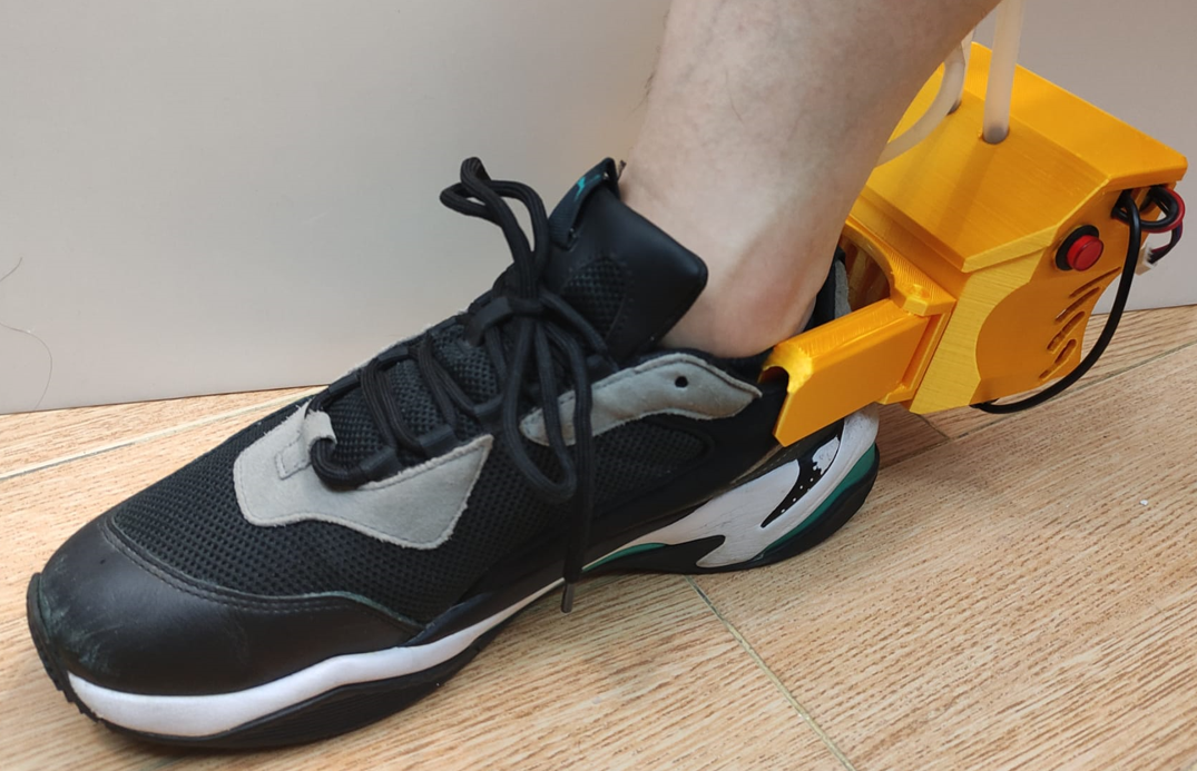
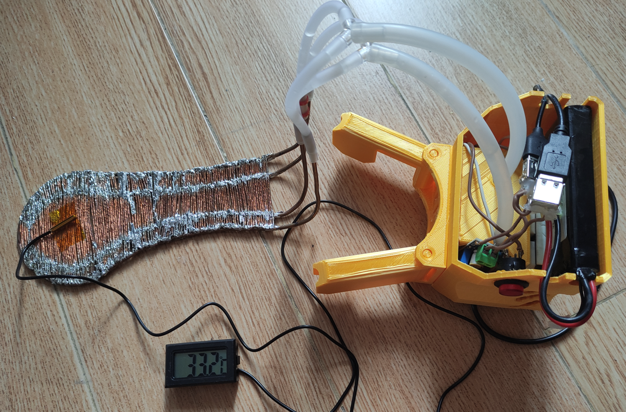
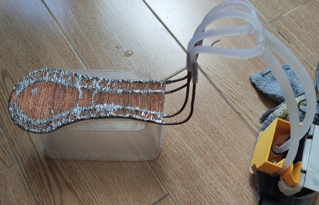
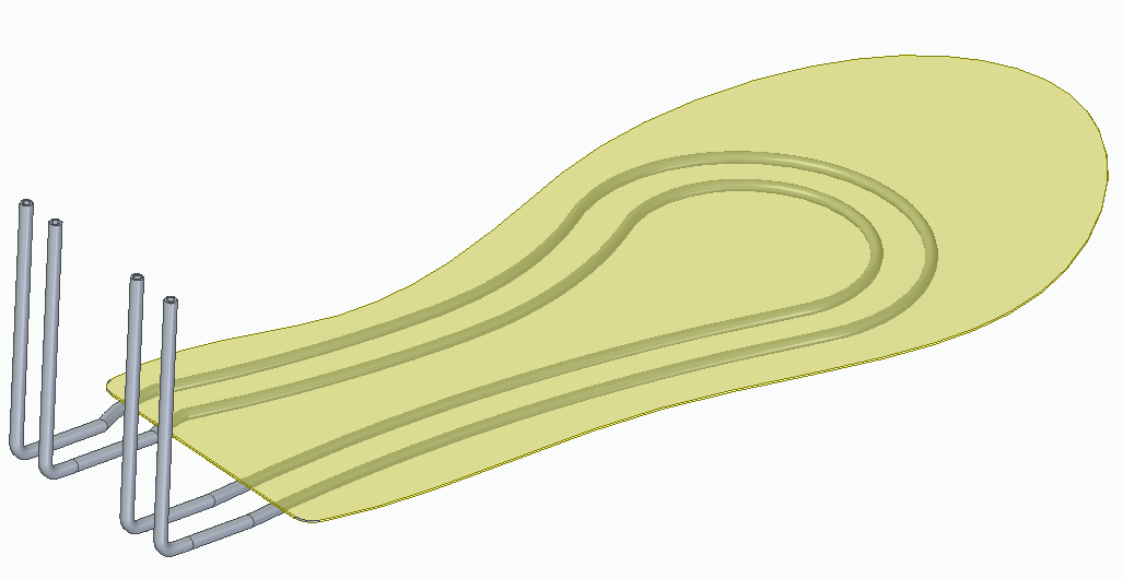
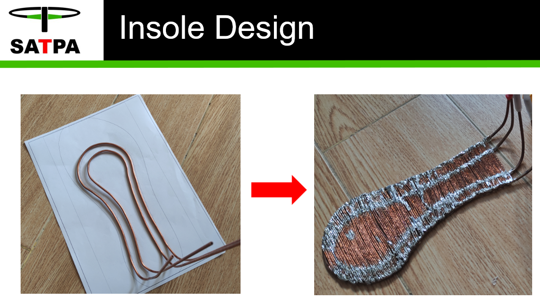
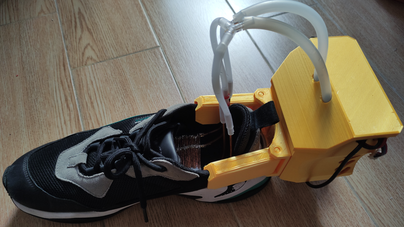 The cooler module with insole
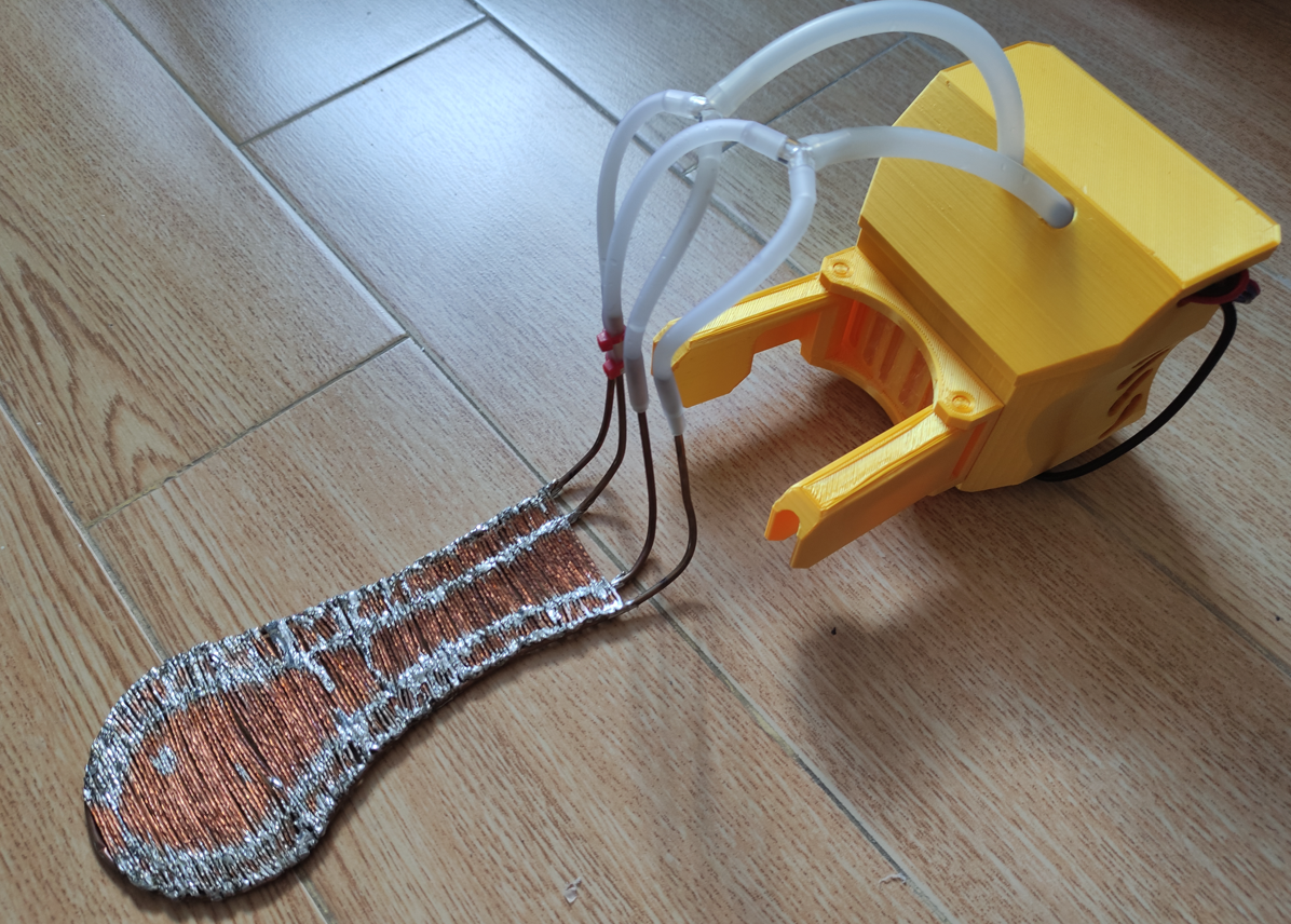


 Scott
Scott
 Josh Starnes
 ken.do
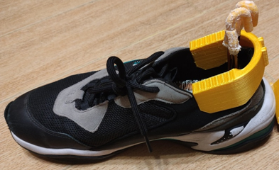
Very interesting project! Will the water pipes or 3D printed parts hit your calves when you walk with this?