Lord Of All Things
This Cyberdeck shall serve as a multi-functional Disaster Recovery Kit and multi-purpose Cybersecurity and Hacking Field-Lab. As such it is fully packed with features as follows:
The Top Part
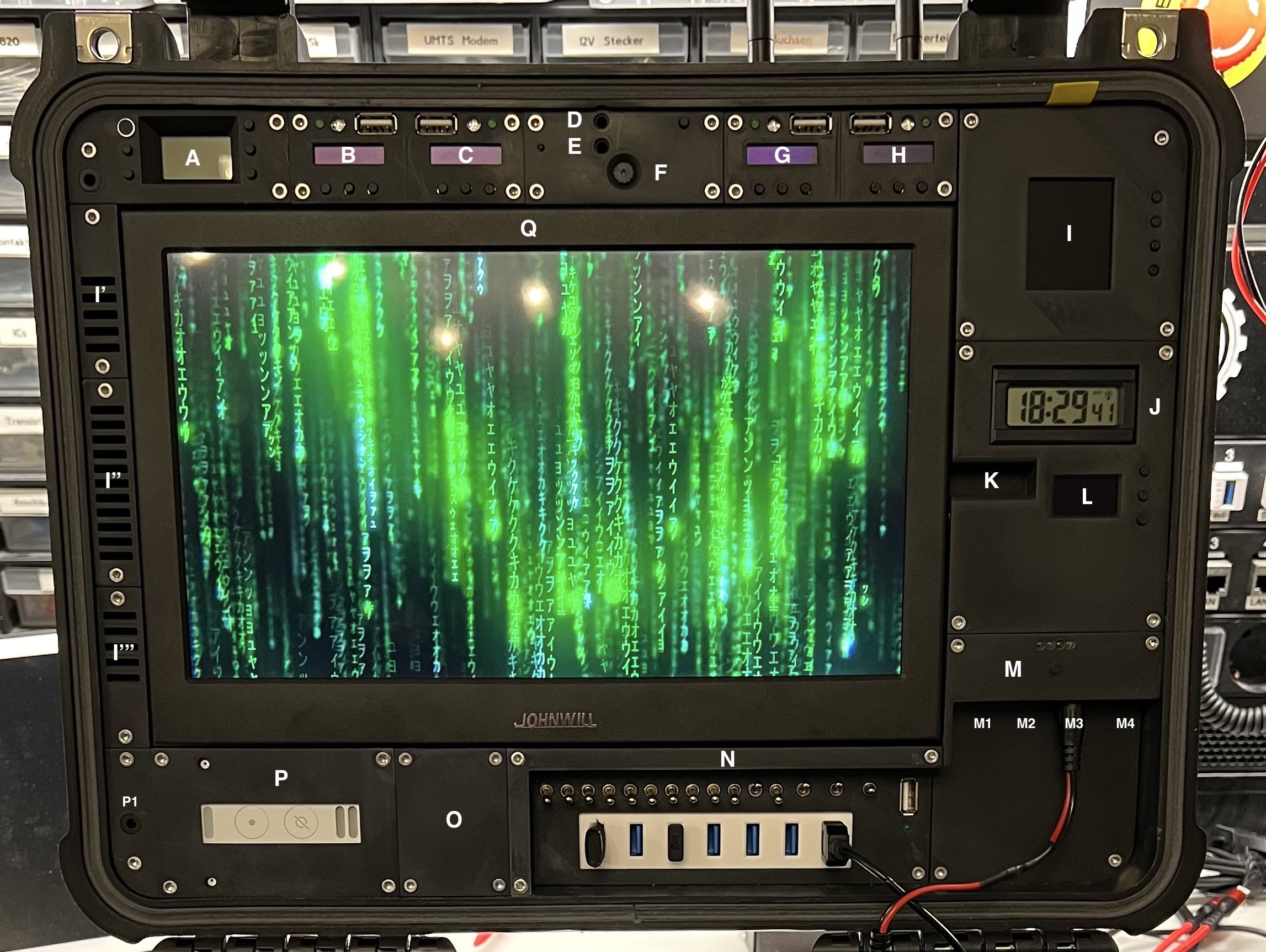
The functional Modules of the Top Part:
- Module A - Radio Transmitter (DONE)
- 88 - 108MHz
- illuminated LCD display
- built-in microphone
- Audio Input (for 3.5mm mini stereo jack plug)
- 4 buttons to control frequency, volume and input source
- external Antenna (on demand mounted)
- Module B - 433MHz Analyzer (WiP)
- ESP32
- 433MHz transmitter and receiver
- 0.91'' 128x32 IIC I2C OLED Display Module
- 3 Buttons
- 1 green status LED
- 1 RGB-LED
- USB socket for programming the ESP32 (in the field)
- external Antenna (on demand mounted)
- Module C - 868MHz Analyzer (WiP)
- ESP32
- 868MHz transmitter and receiver
- 0.91'' 128x32 IIC I2C OLED Display Module
- 3 Buttons
- 1 green status LED
- 1 RGB-LED
- USB socket for programming the ESP32 (in the field)
- external Antenna (on demand mounted)
- Module D - Bluetooth Receiver (DONE)
- Audio Output (for 3.5mm mini stereo jack plug)
- Button for pairing
- Module E - Bluetooth Transceiver (DONE)
- Audio Input (for 3.5mm mini stereo jack plug)
- Status Led
- Module F - Webcam (DONE)
- USB 8MP Webcam
- Module G - Bluetooth Analyzer (WiP)
- ESP32
- 0.91'' 12832 IIC I2C OLED Display Modul
- 3 Buttons
- 1 green status LED
- 1 RGB-LED
- USB socket for programming the ESP32 (in the field)
- Module H - LoRaWAN Analyzer (WiP)
- ESP32 LoRaWAN (Heltec)
- 0.91'' 128x32 IIC I2C OLED Display Modul
- 3 Buttons
- 1 green status LED
- 1 RGB-LED
- USB socket for programming the ESP32 (in the field)
- external Antenna (on demand mounted)
- Module I - Weather Station (WiP)
- ESP32
- 1,8"" Serial SPI TFT LCD Modul
- 4 Buttons
- On the lot side under the 10'' Monitor (Module Q) the following sensors are foreseen:
- IKEA Air Dust Sensor
- 3 different Air Quality / Gas Sensors
- The fan of the Ikea dust sensor ensures that the air is sucked in via I' (through the dust sensor) and further in an encapsulated duct via the other gas sensors so that the air is then released again via I''', with the help of another small fan.
- I': Air intake (and top stereo speaker)
- I'': Air intake for BMP280
- I''': Air outlet (incl. a small fan)
![]()
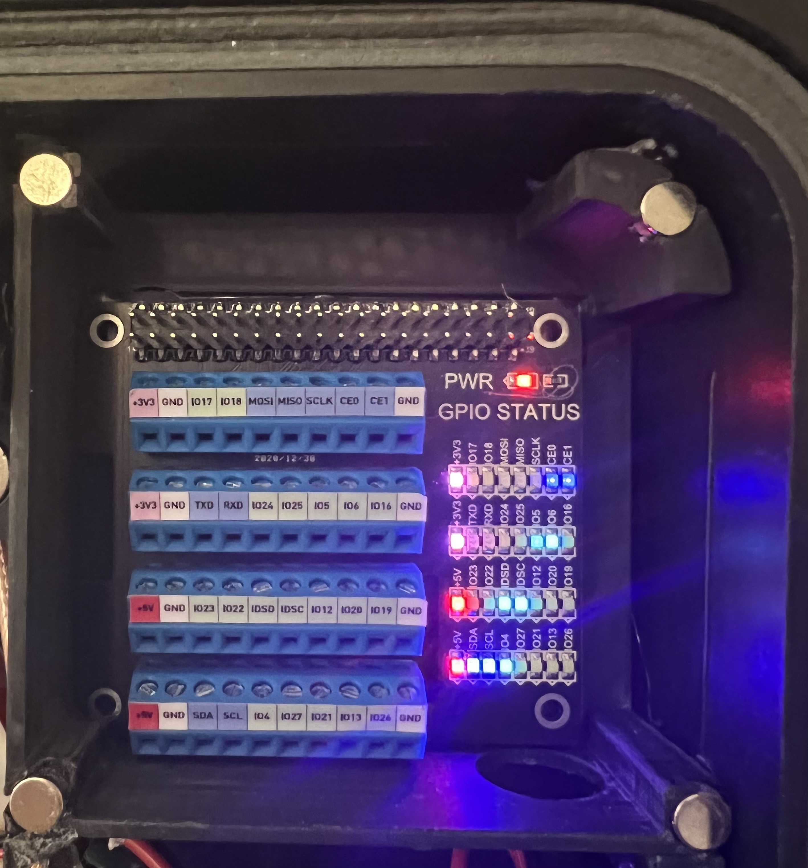
- And "One more Thing":
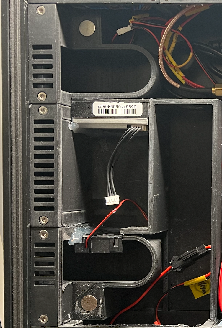
- As a small Hidden Gadget, there is a GPIO Module behind the weather station module that is connected to the Raspberry Pi. To reach the GPIO ports, all you have to do is gently pull the yellow tab and the magnetically held cover will pop off.
![]()
- Module J - Clock (DONE)
- Radio clock module
- Module K - Monitor Audio Output (DONE)
- Audio Output (for 3.5mm mini stereo jack plug)
- Module L - Generic ESP (ToDo)
- ESP32
- 0,96 Zoll OLED Display I2C SSD1306 Chip 128 x 64 Pixel
- 3 buttons
- Module M - USV & Patch Panel (DONE)
- 10.000mAh 5V USV
- M1: Ethernet Port of Raspberry Pi4
- M2: Audio Output of Raspberry Pi4 (for 3.5mm mini stereo jack plug)
- M3: 12V Connector (Power Source for Top Case)
- M4: Ethernet Port of LTE/WLAN Router
- Module N - Power Switch Panel (DONE)
- 2-Position Switches (ON/OFF - Left to Right)
- 1: Module A
- 2: Module B
- 3: Module C
- 4: Module D
- 5: Module E
- 6: Module G
- 7: Module H
- 8: Module I
- 9: Module L
- 10: LTE/WLAN Router (hidden under Module Q)
- 11: FireTV Stick (hidden under Module Q)
- 12: Module P
- 3-Position Switches (ON/OFF/ON - Left to Right)
- 13: Switch to select the Power Source for Switches 1..12 (USV or 12V-5V Converter C)
- 14: Switch to select the Power Source for the Monitor/Module Q (USV or 12V-5V Converter B)
- 15: Switch to select the Power Source for the RasPi4 (USV or 12V-5V Converter A)
- USB Socket (for external Power Sources, like an USB Power Bank)
- Status LED (USV / External Power)
- 2-Position Switches (ON/OFF - Left to Right)
- Module O - UNUSED
- Placeholder for another module in the future.
- Module P - Alexa (DONE)
- Amazon Echo Flex (brutally stripped down to the bare minimum)
- P1: Audio Output of Raspberry Pi4 (for 3.5mm mini stereo jack plug)
- Module Q - 10'' Monitor (DONE)
- HDMI input #1 for the RasPi4 (auto select)
- HDMI input #2 for the FireTV Stick (auto select)
- HIDDEN (behind Module Q)
- Raspberry Pi 4
- 5-Port USB 3.0 HUB
- FireTV Stick
- LTE USB Module + LTE/WLAN Router
- Nooelec SDR with external antenna
- 3x Buck Converter Step Down (12v -> 5V 3A)
The Bottom Part
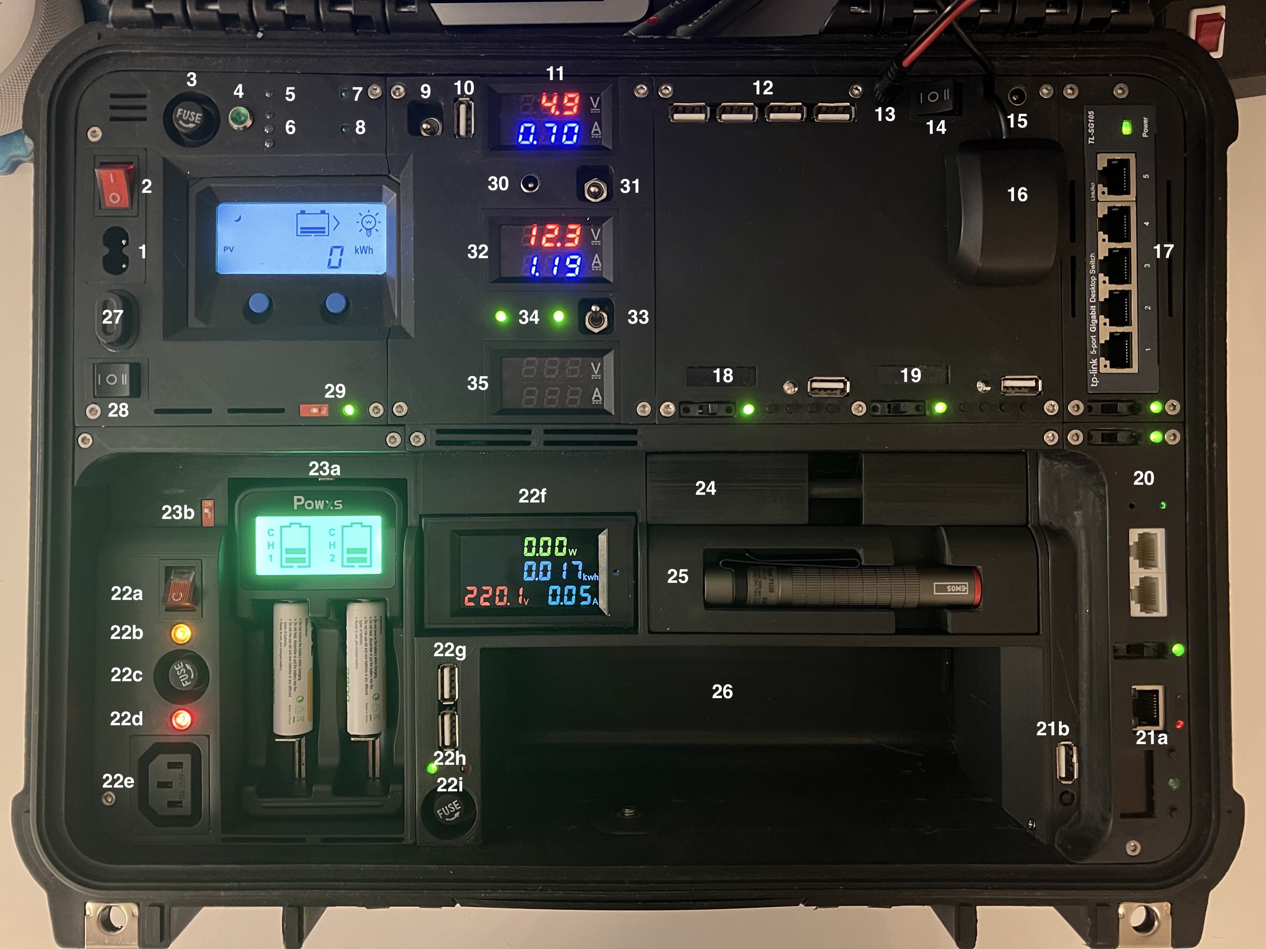
The functional Modules of the Bottom Part:
- 230V Power Inlet (related cable can be stored in 26)
- Main Power Switch for external 230V Power Supply
- 230V Fuse
- 230V Status LED (to check if fuse is OK)
- Status LED of the internal Power Supply (230V -> 5V / 60 Watt) Input: 230V
- 3 Status Led (Traffic Lights) of internal Battery Charger (Top/Green: Full, Middle/Orange: Loading, Bottom/Red: Error)
- Status LED of the internal Power Supply (230V -> 5V / 60 Watt) Output: 5V
- Status LED of Battery Charger Output
- 3-Position Switch
- Top Position: Use the external Power Supply for internal 5V System
- Middle Position: OFF
- Bottom Position: Use the internal Power Supply / Solar Charger for the internal 5V System
- USB Socket for external 5V Power Supply (e.g. Power Bank)
- Volt & Ampere Meter for the internal 5V System
- 4 USB Sockets to connect any USB Device (for charging) or the USB LED Lights (as stored in 26)
- 12V Power Outlet for the Top-Case (Default)
- 3-Position Switch
- Left Position (I): Connect the internal 12V lead gel battery with internal Power Mechanisms / Solar Charger
- Middle Position: OFF (Battery disconnected from anything -> prevent battery discharge)
- Right Position (II): Connect the internal 12V lead gel battery eclusively with the Power Outlet 15
- 12V Power Outlet (see 14)
- USB GPS Mouse, connected with the Module N - Power Switch Panel of the Top Case
- TP-Link 5-Port Gigabit Router
- Switch + green Status LED
- RFID (125KHz, 13,56 MHz) Module
- ESP32
- 0.91'' 128x32 IIC I2C OLED Display Modul
- 4 Buttons
- 1 RGB LED
- USB Socket for (re-)programming (in the field)
- NFC Module
- ESP32
- 0.91'' 128x32 IIC I2C OLED Display Modul
- 4 Buttons
- 1 RGB LED
- USB Socket for (re-)programming (in the field)
- TP-Link Router
- Stripped down TP-Link WLAN Router
- Switch + green Status LED
- Custom Network Analyzer
- Right Part
- ESP32
- 0,96 Zoll OLED Display I2C SSD1306 Chip 128 x 64 Pixel
- Ethernet Port
- 2 Buttons
- 1 Green LED
- Switch + green Status LED
- Left Part
- USB Socket for (re-)programming (in the field)
- Reset Button
- Right Part
- 300Watt Inverter
- Main Power Switch (12V Input)
- 230V Output Status Led (RAW Inverter Output, before Fuse)
- 230V Fuse
- 230V Output Status Led (after Fuse)
- 230V Outlet
- 230V Volt & Ampere Meter (after Fuse)
- Battery Charger
- Switch
- 5V battery charger with 2 charging slots for all battery types (incl. LiPos)
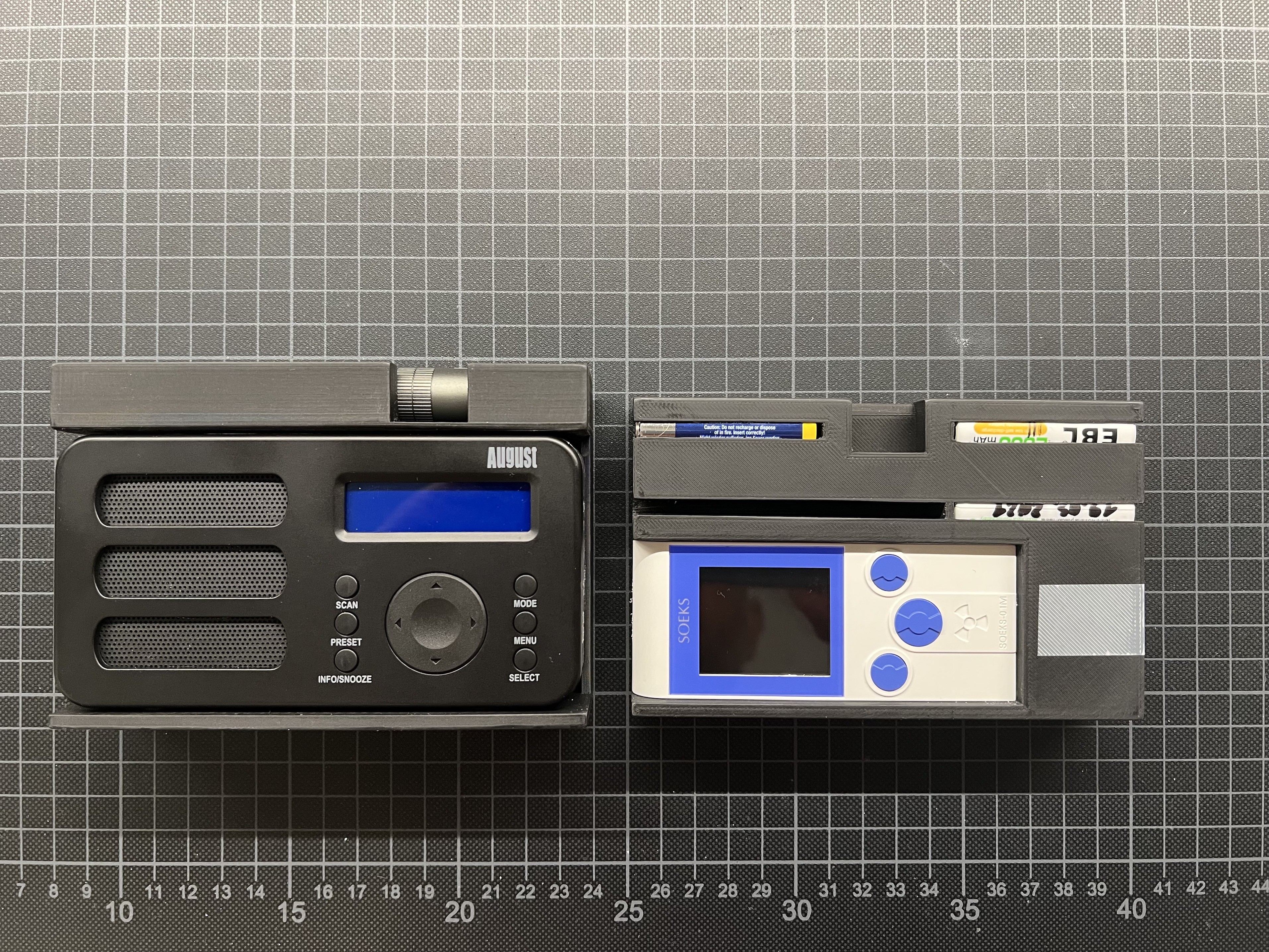
- Pull-out compartment
![]()
- incl. a mobile Geiger counter
- incl. various AA and AAA rechargeable batteries
- Pull-out compartment
- incl. a World receiver and DAB radio
- incl. a mini flashlight
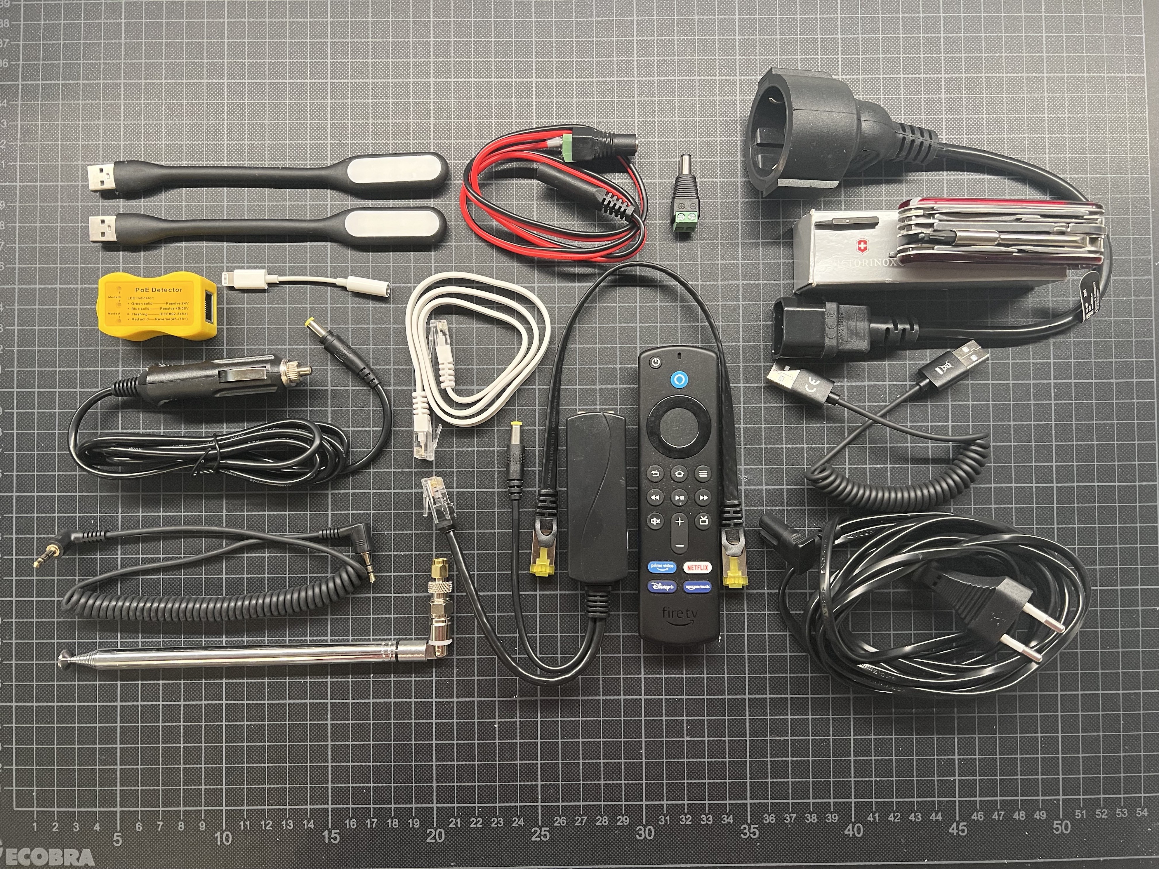
- Storage Compartment
![]()
- Power Cables (230V, 12V, Car Adapter, ...)
- Network Cables
- Audio Cables
- USB Cables
- USB LED Lights
- Several Adapters (Audio, 12V)
- PoE Analyzer
- Swiss Knife: CyberTool
- PoE Extractor
- Remote for FireTV
- ...
- Generic Power Inlet (for 12-48V DC / Solar Panels / ...)
- 2-Position Switch for the generic Power Inlet
- Left Position (I): Router Power from Power Inlet (27) direct to the Solar Charger Input (e.g. if external Solar Cells are connected(
- Middle Position: OFF (External Power Inlet is disconnected from all internal components)
- Right Position (II): Route the external Power to the VA Meter (for Analysis) and eventually use it for the 12-24V Step-Down Buck Converter (5V Output / 10A)
- Internal Fan
- Red Micro Switch
- Green Status LED
- Battery Charger Outlet
- Provides the option to use the internal Battery Charger to also load an external battery
- 3-Position Switch
- Top Position: Connect the internal 12V Battery with the internal Battery Charger
- Middle Position: OFF
- Bottom Position: Connect the internal 12V Battery with the Solar Charger (and enable the usage of the 300W Inverter)
- Volt & Ampere Meter for the internal 12V Battery System
- 3-Position Power Switch
- Top Position: Use the internal Power Source (12V Battery) for the internal Step-Down Converter (5V 10A Output)
- Middle Position: OFF (internal Step-Down Converter)
- Bottom Position; Use some external Power Source (e.g. from Socket 27 via direct connect or Solar Charger) for the internal Step-Down Converter (5V 10A Output)
- Status LEDs of the internal Step-Down Converter (5V 10A Output)
- Left LED: Step-Down Converter Output is OK
- Right LED: Step-Down Converter Input is OK
- Volt & Ampere Meter for the external Power Source connected to Inlet 27