Close
0%
0%

The Black Beast

A Raspberry Pi Cyberdeck

Public Chat
Similar projects worth following
The "Black Beast" prototype is not only a heavy-duty Cyberdeck, but also an experimental sensor and hacking platform, which is still work in progress. It is my first Cyberdeck and I started building it in January 2022. The build process (which is still ongoing, especially for the SW part) was very iterative and never followed a predefined plan. I had to adjust many of my custom 3 prints during assembly (file, grind, saw, glue) and actually never intended to publish this prototype, let alone document it in a reproducible way. In this respect, I can only show snapshots of the construction process here and the 3D files are not all 100% accurate. In addition, as I made use of a lot of existing electronics and spare parts of my maker space / electronic lab, the component list is not 100% complete. How ever, I hope this "Black Beast" can still serve as a source of inspiration, even if it would be very challenging to rebuild it.

This Cyberdeck shall serve as a multi-functional Disaster Recovery Kit and multi-purpose Cybersecurity and Hacking Field-Lab. As such it is fully packed with features as follows:
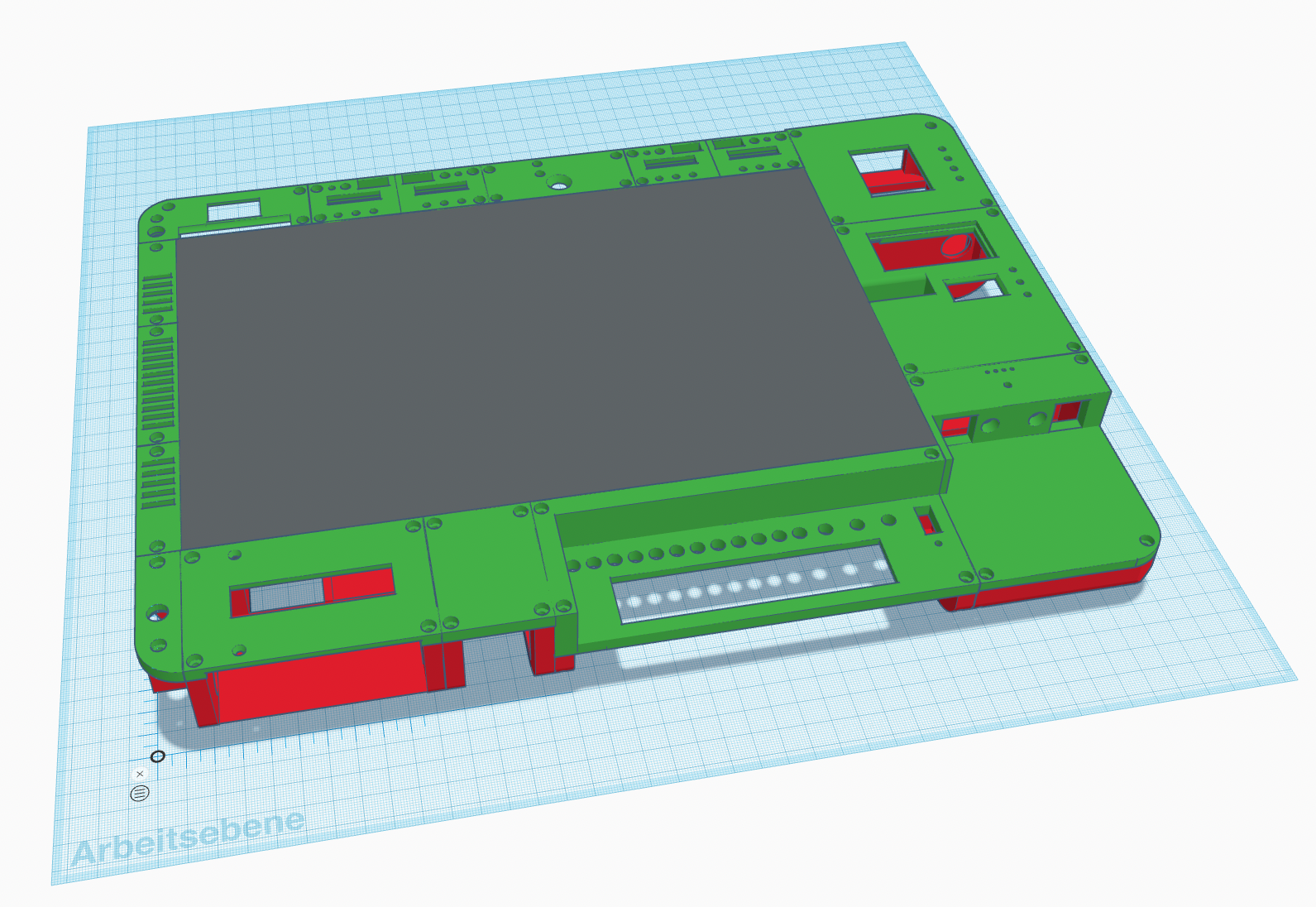
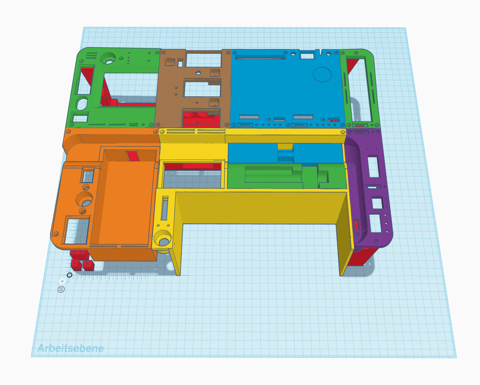
The Top Part

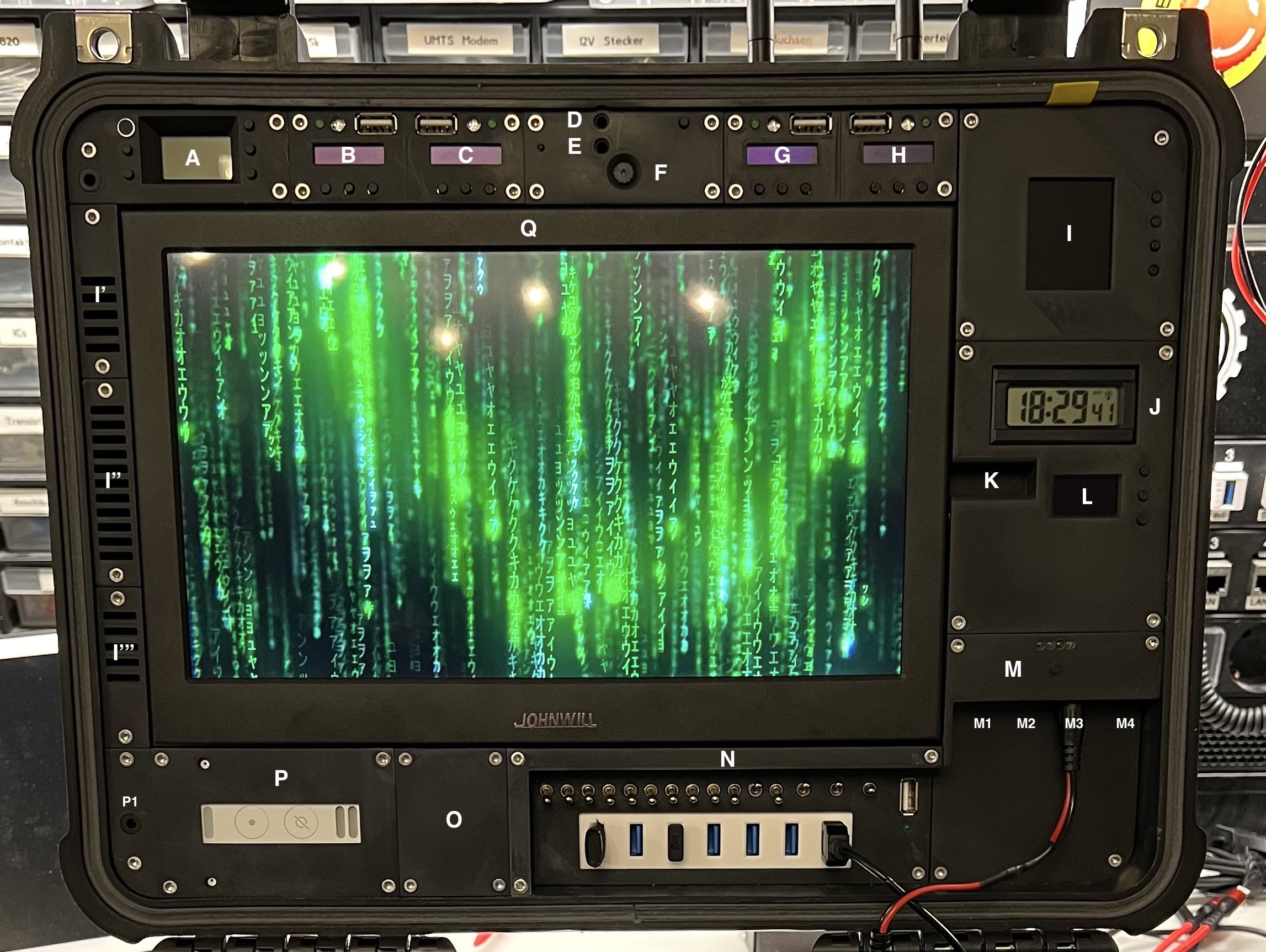
The functional Modules of the Top Part:

  • Module A - Radio Transmitter (DONE)
    • 88 - 108MHz
    • illuminated LCD display
    • built-in microphone
    • Audio Input (for 3.5mm mini stereo jack plug)
    • 4 buttons to control frequency, volume and input source
    • external Antenna (on demand mounted)
  • Module B - 433MHz Analyzer (WiP)
    • ESP32
    • 433MHz transmitter and receiver 
    • 0.91'' 128x32 IIC I2C OLED Display Module
    • 3 Buttons
    • 1 green status LED
    • 1 RGB-LED
    • USB socket for programming the ESP32 (in the field)
    • external Antenna (on demand mounted)
  • Module C - 868MHz Analyzer (WiP)
    • ESP32
    • 868MHz transmitter and receiver 
    • 0.91'' 128x32 IIC I2C OLED Display Module
    • 3 Buttons
    • 1 green status LED
    • 1 RGB-LED
    • USB socket for programming the ESP32 (in the field)
    • external Antenna (on demand mounted)
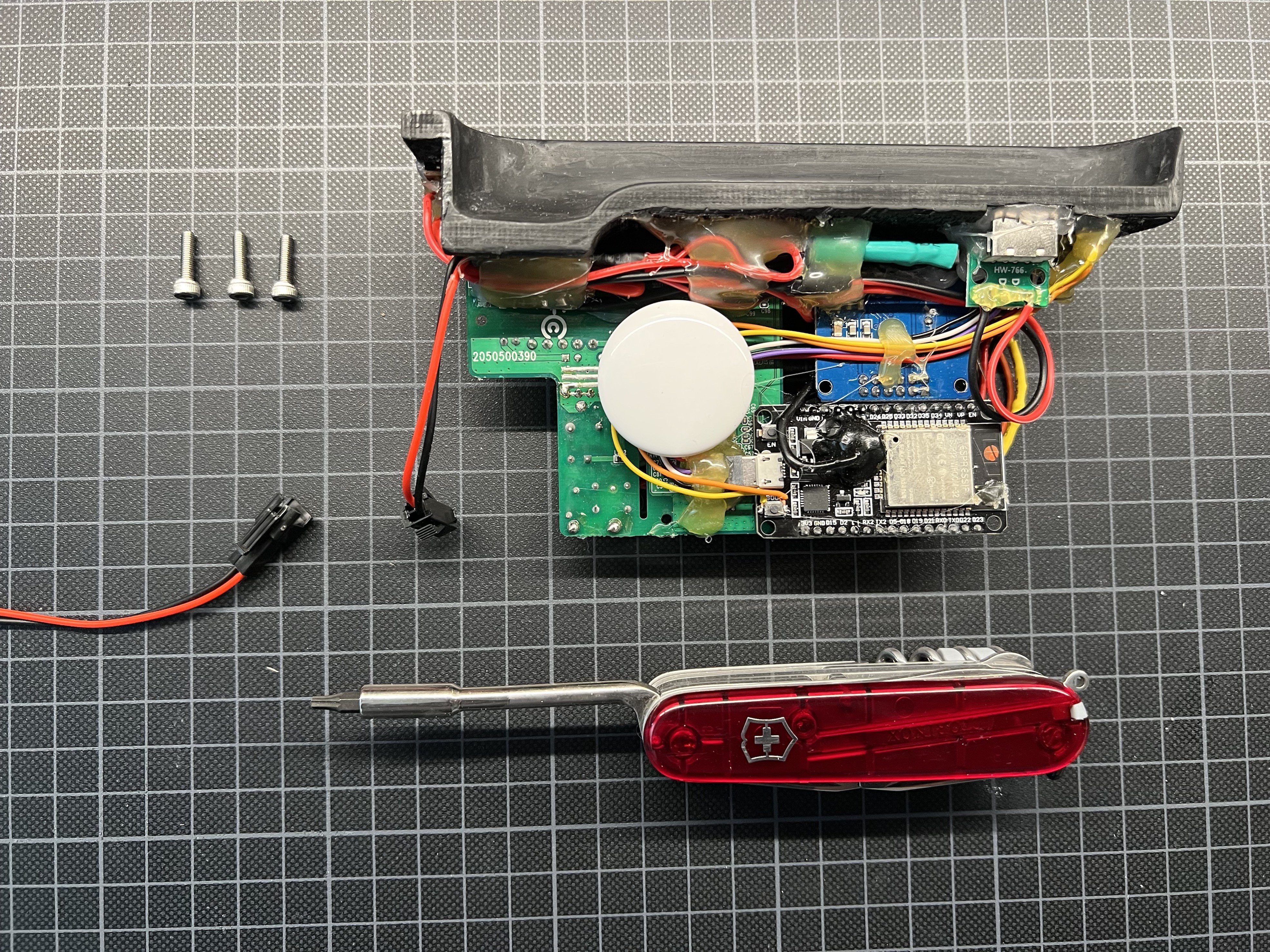
  • Module D - Bluetooth Receiver (DONE)
    • Audio Output (for 3.5mm mini stereo jack plug)
    • Button for pairing
  • Module E - Bluetooth Transceiver (DONE)
    • Audio Input (for 3.5mm mini stereo jack plug)
    • Status Led
  • Module F - Webcam (DONE)
    • USB 8MP Webcam
  • Module G - Bluetooth Analyzer (WiP)
    • ESP32
    • 0.91'' 12832 IIC I2C OLED Display Modul
    • 3 Buttons
    • 1 green status LED
    • 1 RGB-LED
    • USB socket for programming the ESP32 (in the field)
  • Module H - LoRaWAN Analyzer (WiP)
    • ESP32 LoRaWAN (Heltec)
    • 0.91'' 128x32 IIC I2C OLED Display Modul
    • 3 Buttons
    • 1 green status LED
    • 1 RGB-LED
    • USB socket for programming the ESP32 (in the field)
    • external Antenna (on demand mounted)
  • Module I - Weather Station (WiP)
    • ESP32
    • 1,8"" Serial SPI TFT LCD Modul
    • 4 Buttons
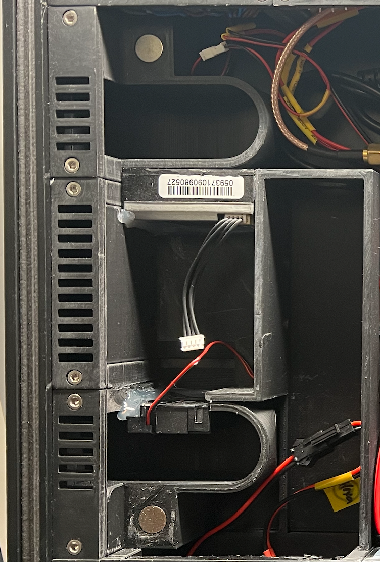
    • On the lot side under the 10'' Monitor (Module Q) the following sensors are foreseen:
      • IKEA Air Dust Sensor
      • 3 different Air Quality / Gas Sensors
      • The fan of the Ikea dust sensor ensures that the air is sucked in via I' (through the dust sensor) and further in an encapsulated duct via the other gas sensors so that the air is then released again via I''', with the help of another small fan.
    • I': Air intake (and top stereo speaker)
    • I'': Air intake for BMP280
    • I''': Air outlet (incl. a small fan)
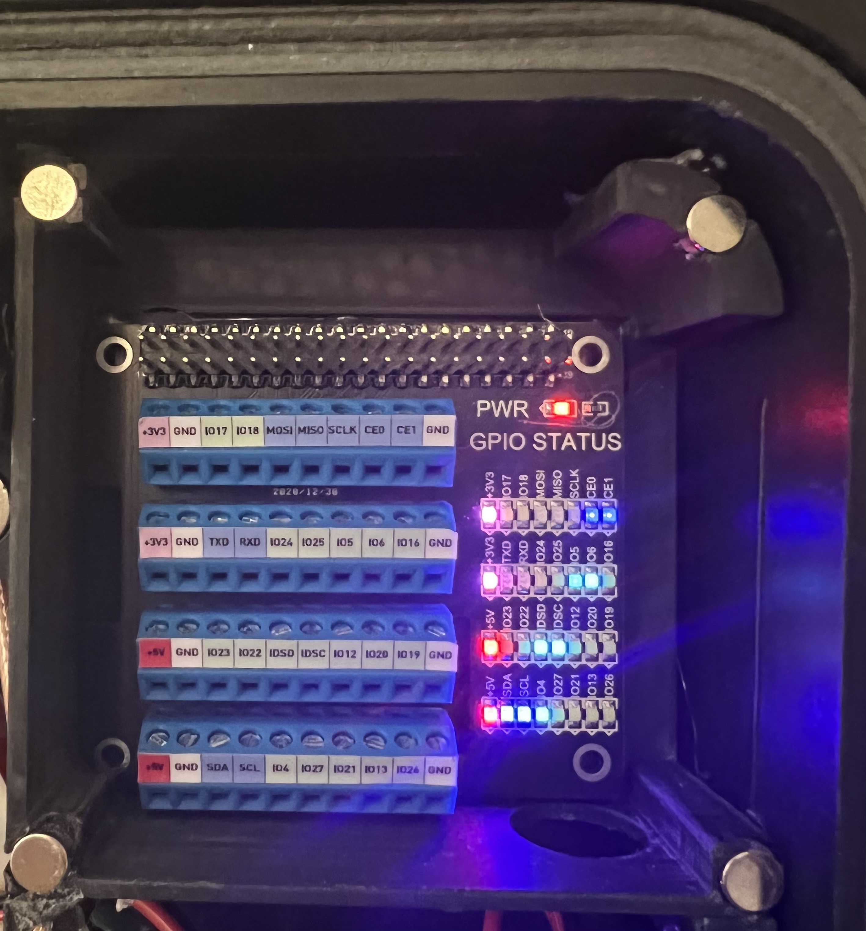
    • And "One more Thing":
      • As a small Hidden Gadget, there is a GPIO Module behind the weather station module that is connected to the Raspberry Pi. To reach the GPIO ports, all you have to do is gently pull the yellow tab and the magnetically held cover will pop off.
  • Module J - Clock (DONE)
    • Radio clock module
  • Module K - Monitor Audio Output (DONE)
    • Audio Output (for 3.5mm mini stereo jack plug)
  • Module L - Generic ESP (ToDo)
    • ESP32
    • 0,96 Zoll OLED Display I2C SSD1306 Chip 128 x 64 Pixel
    • 3 buttons
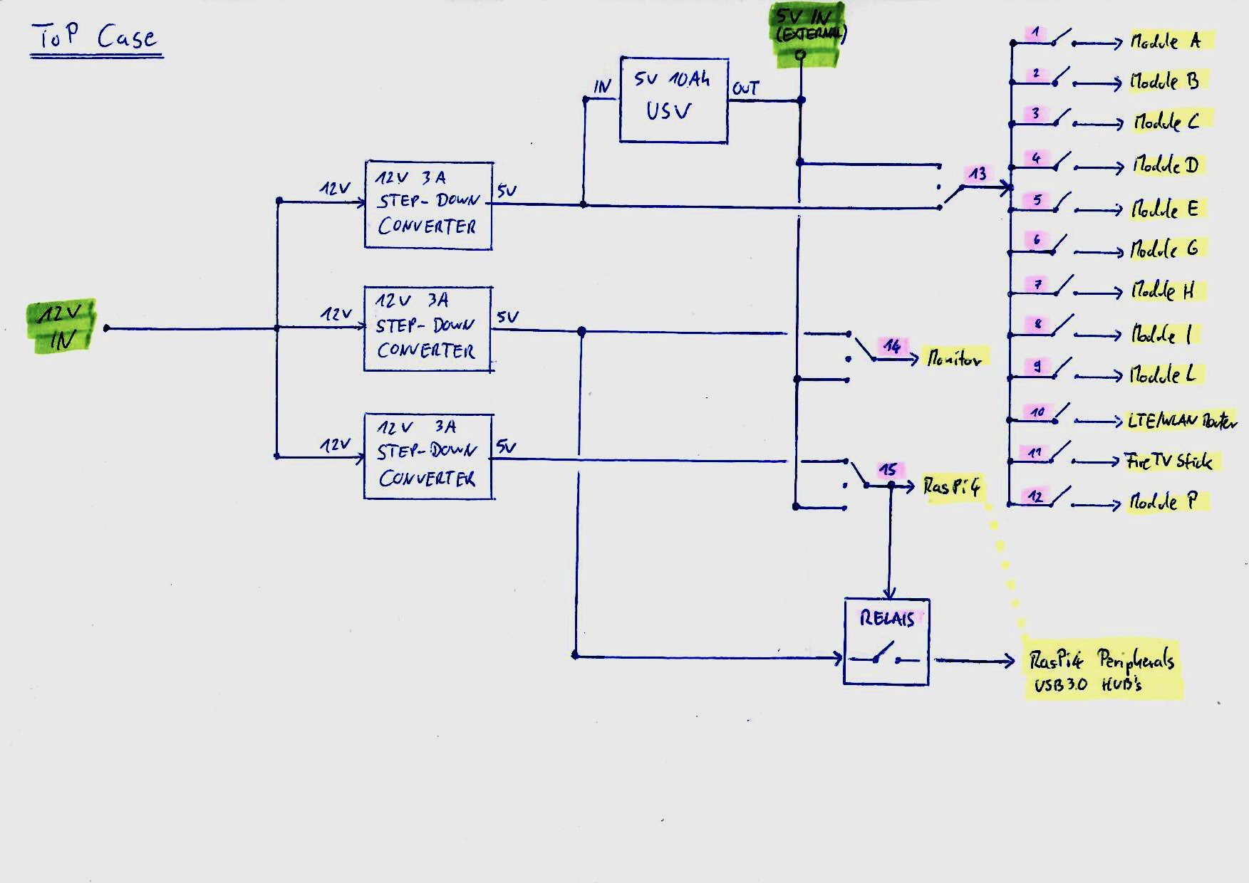
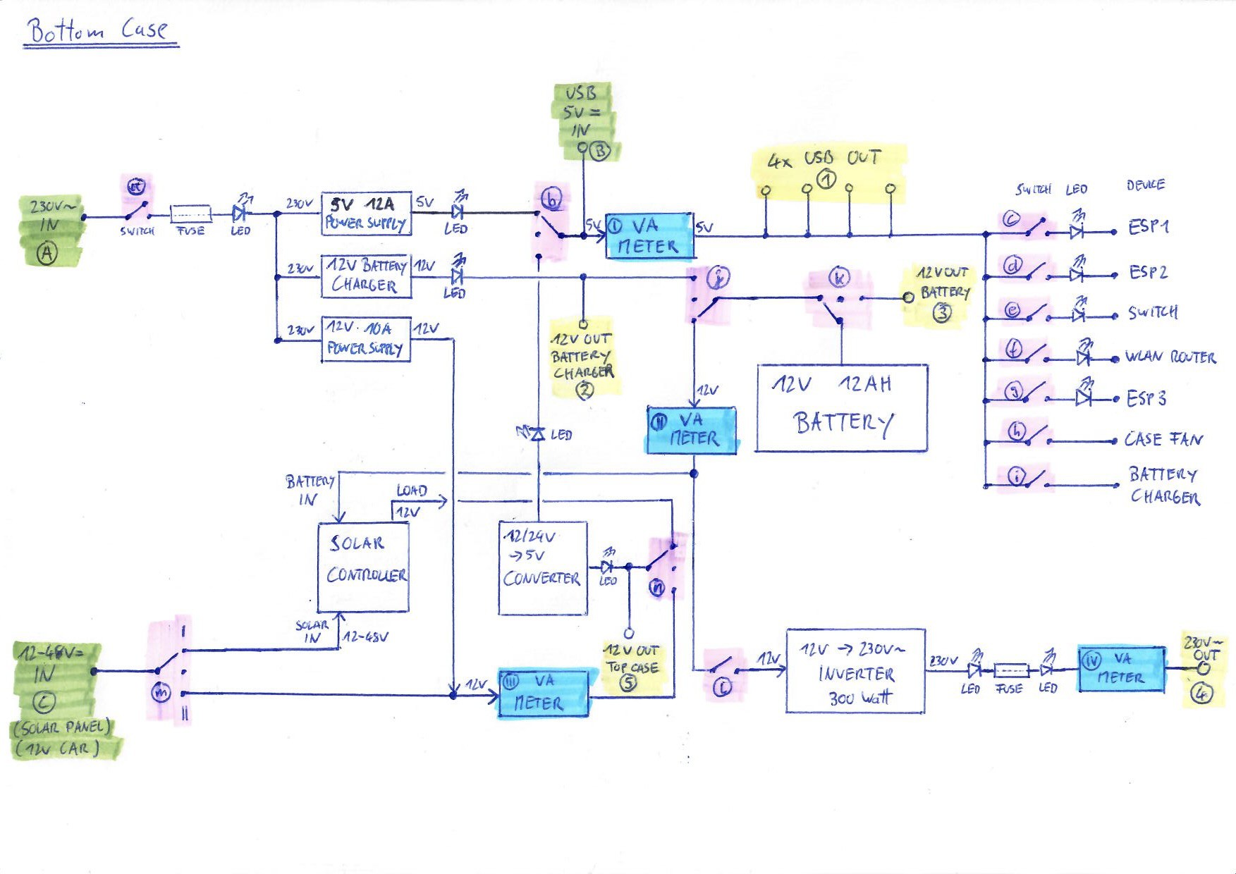
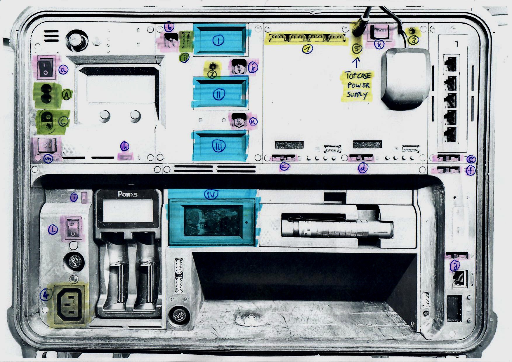
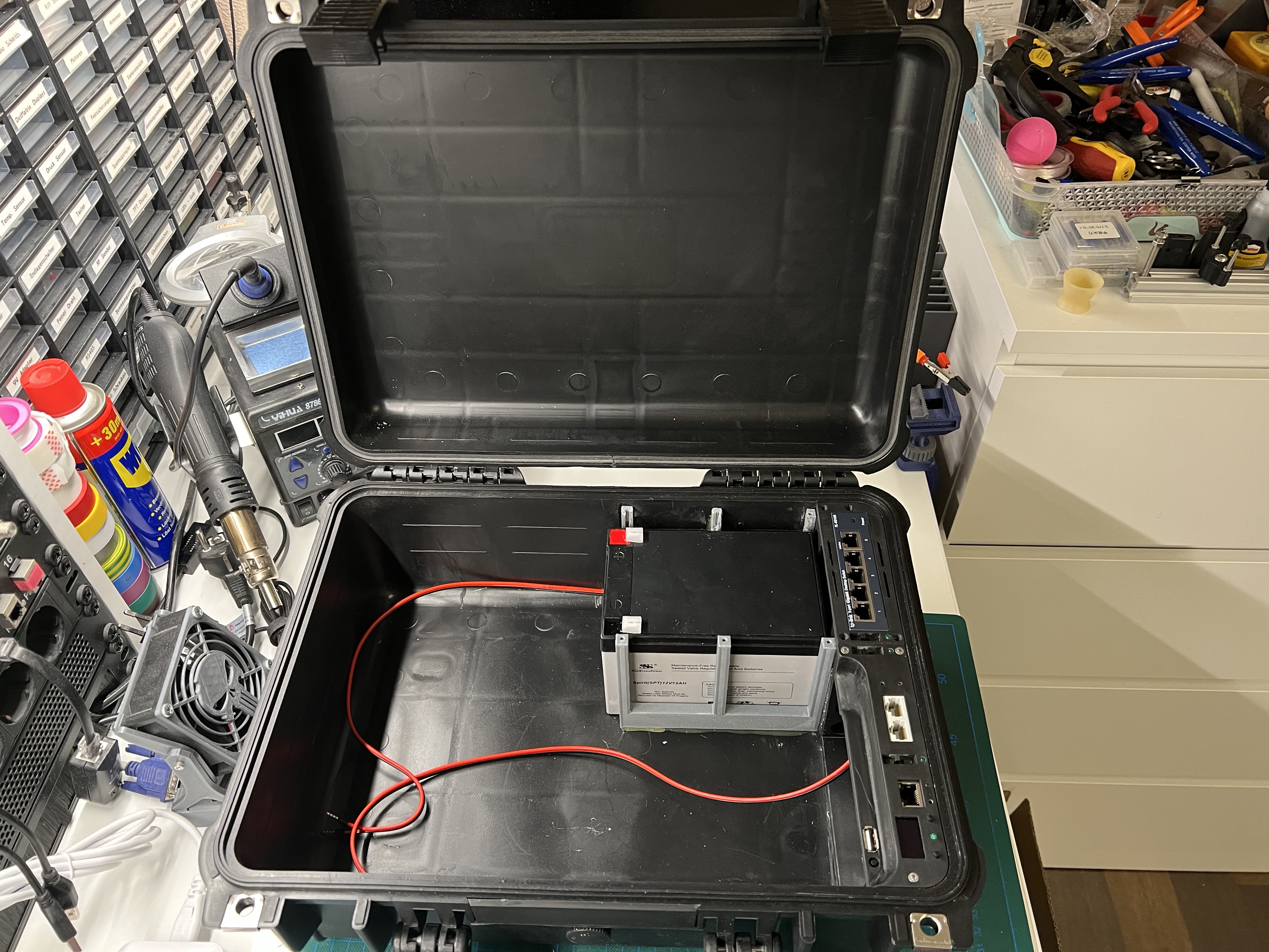
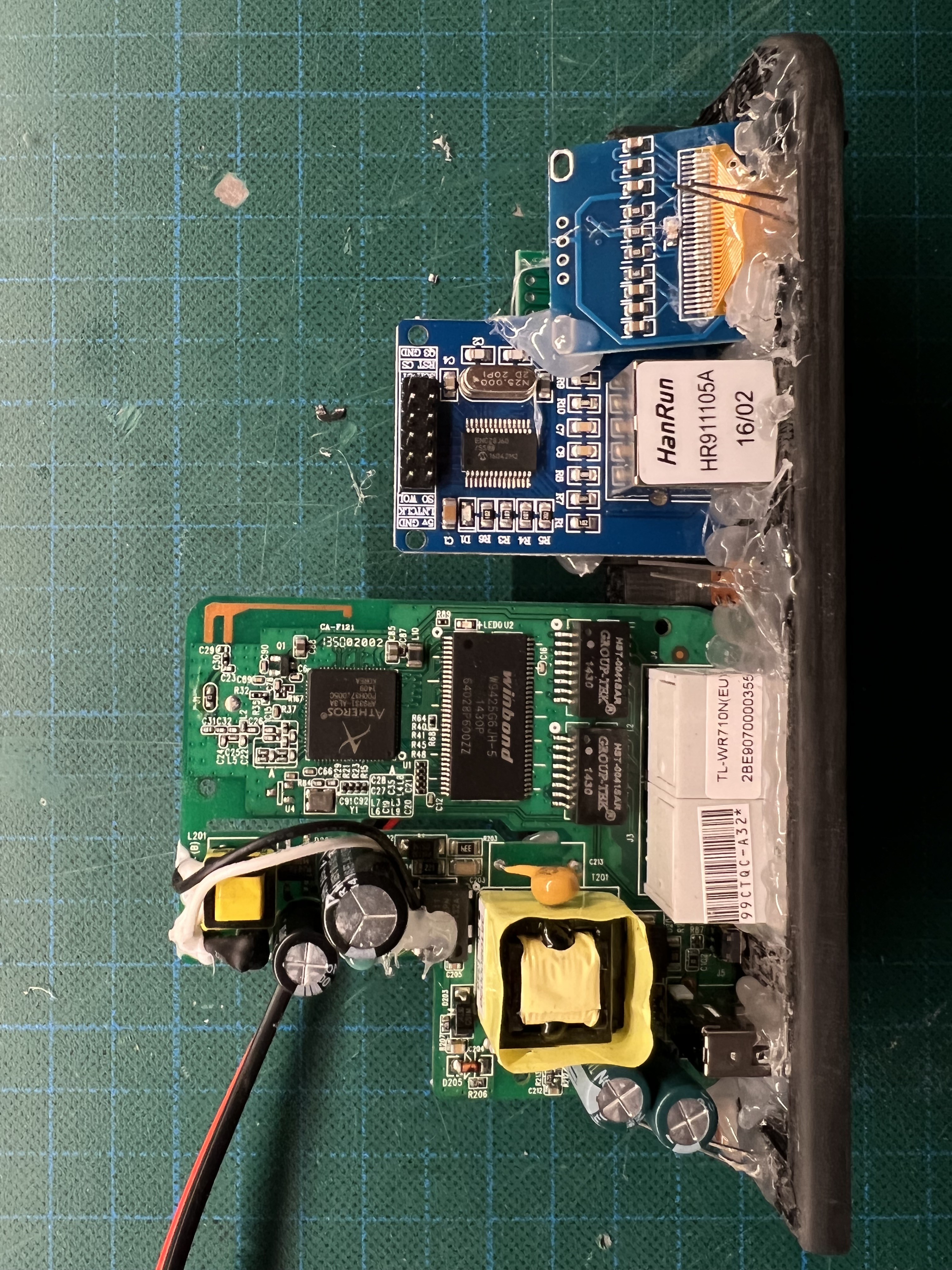
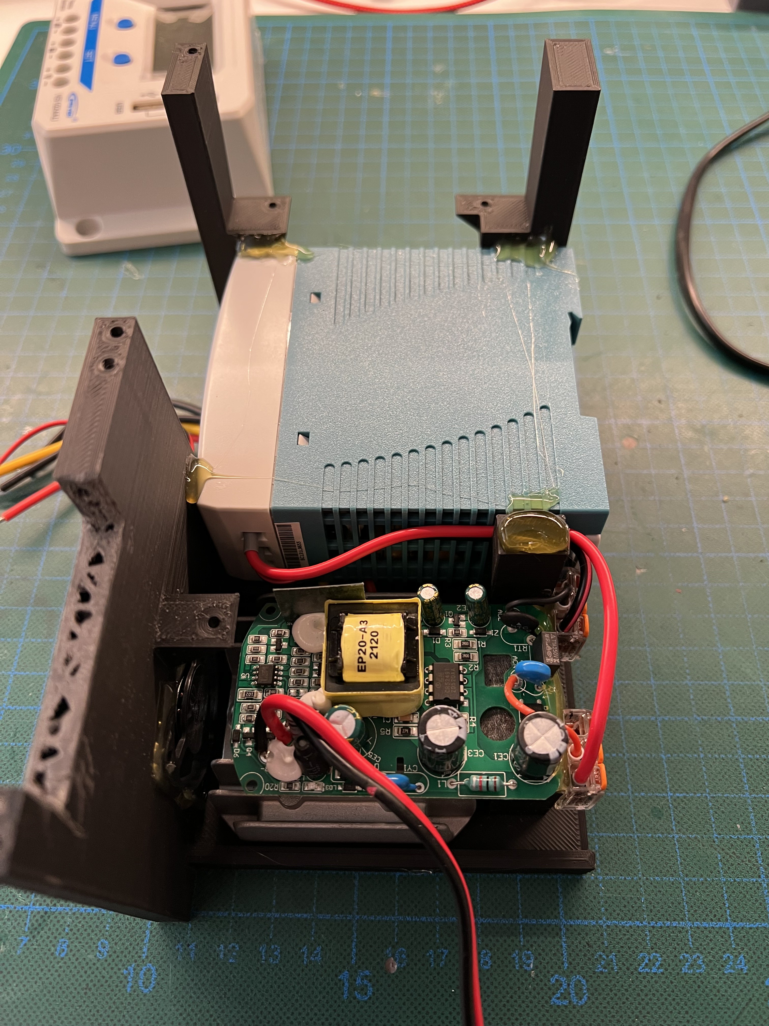
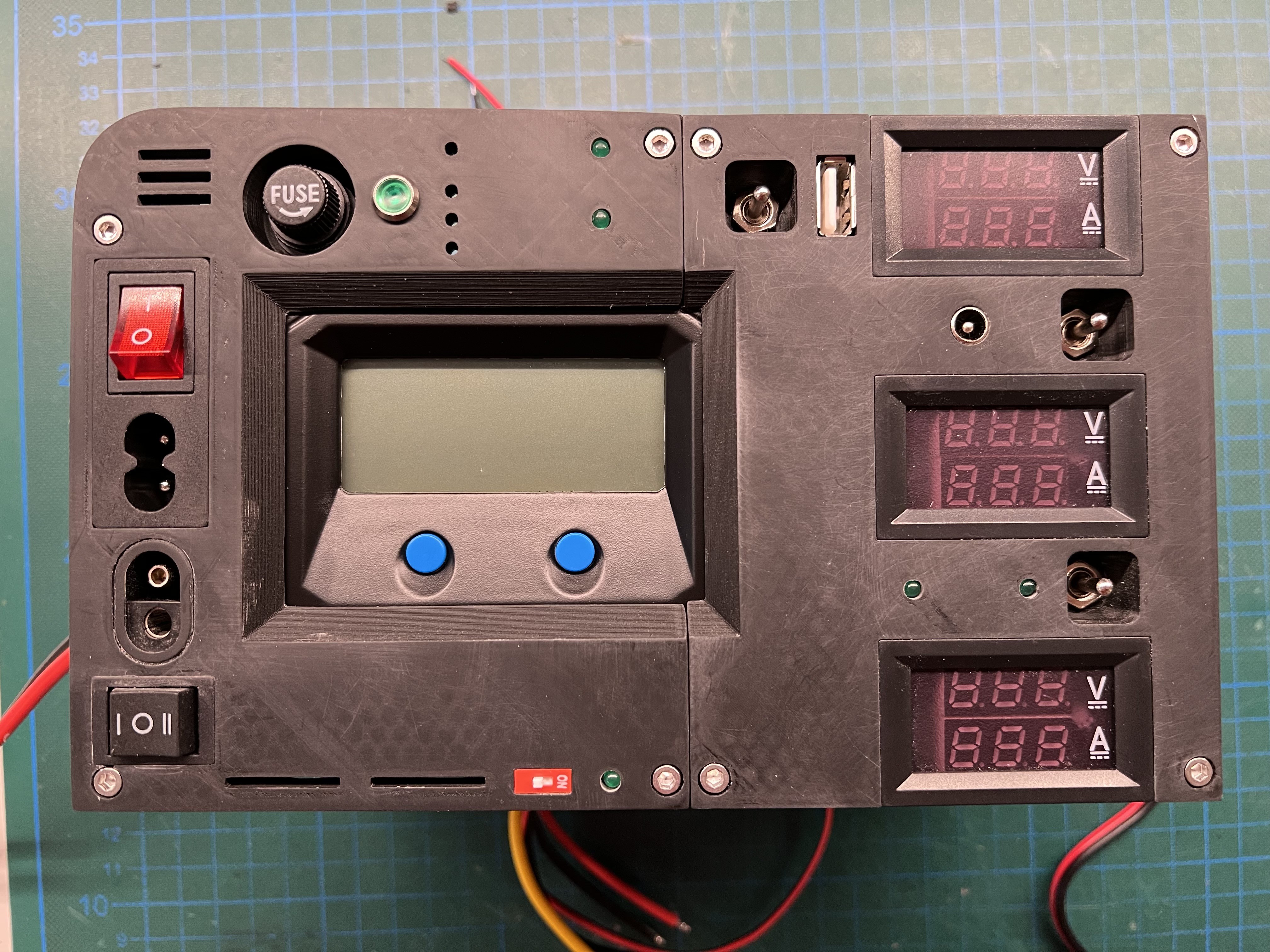
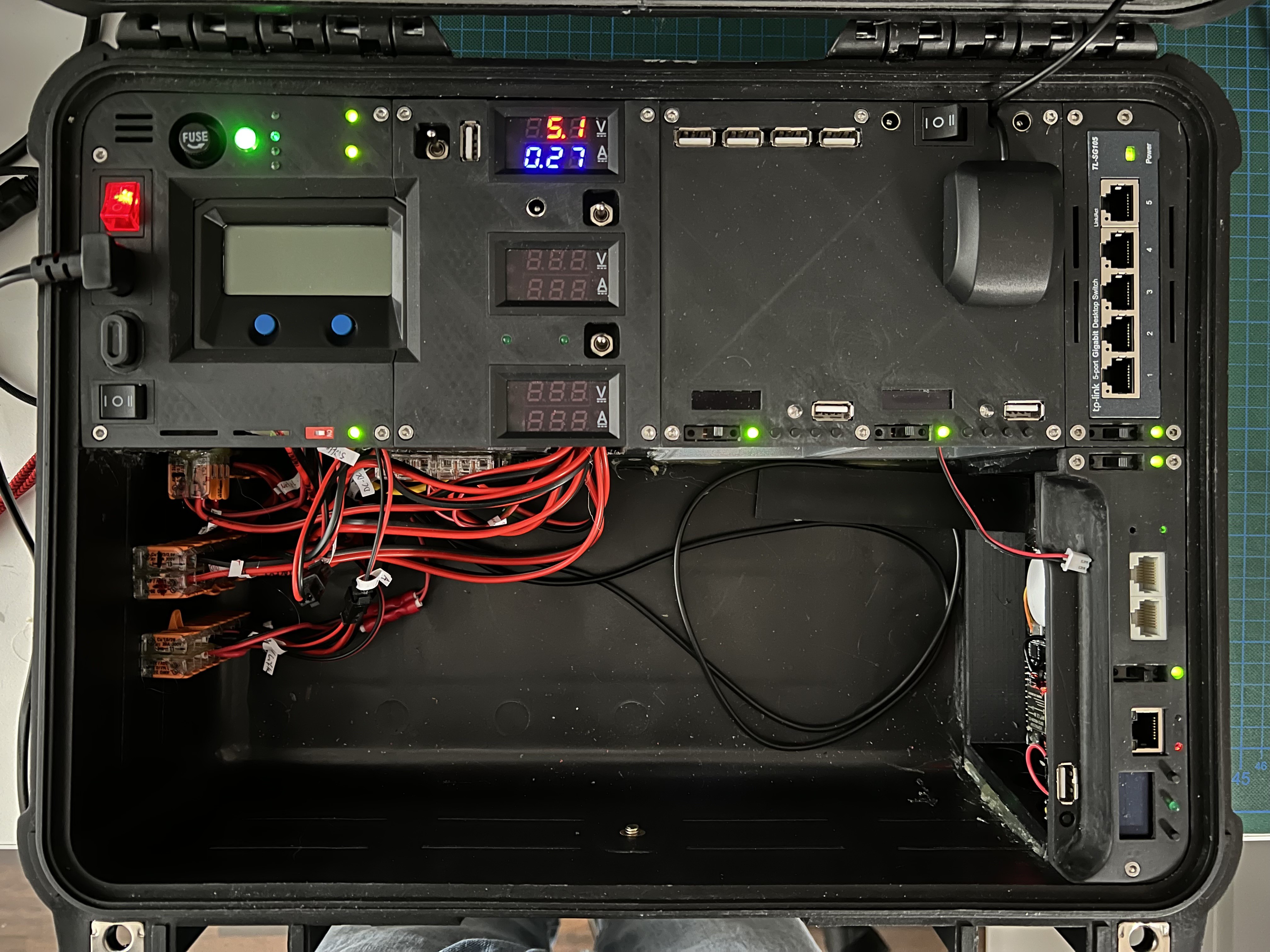
  • Module M - USV & Patch Panel (DONE)
    • 10.000mAh 5V USV
    • M1: Ethernet Port of Raspberry Pi4
    • M2: Audio Output of Raspberry Pi4 (for 3.5mm mini stereo jack plug)
    • M3: 12V Connector (Power Source for Top Case)
    • M4: Ethernet Port of LTE/WLAN Router 
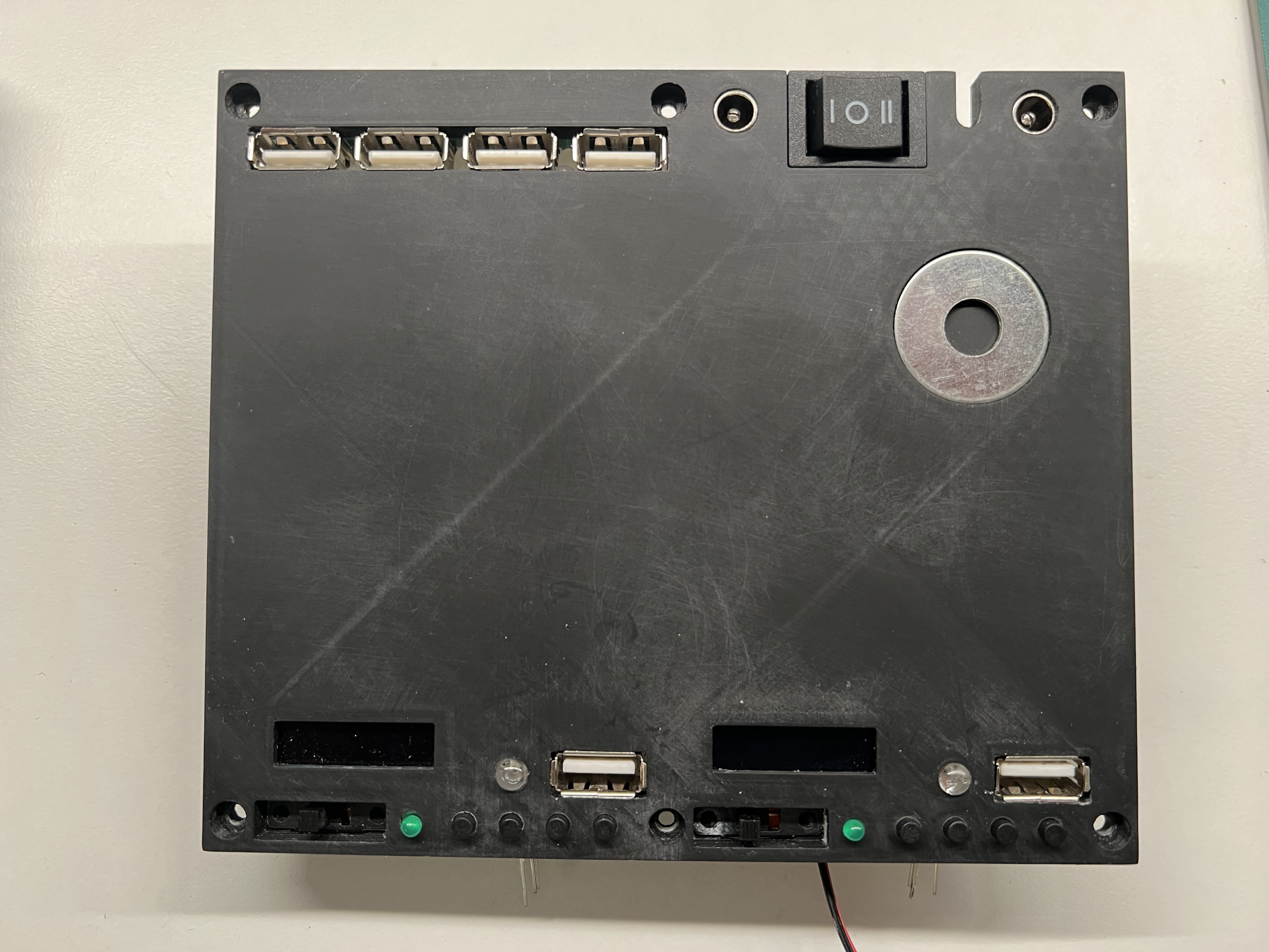
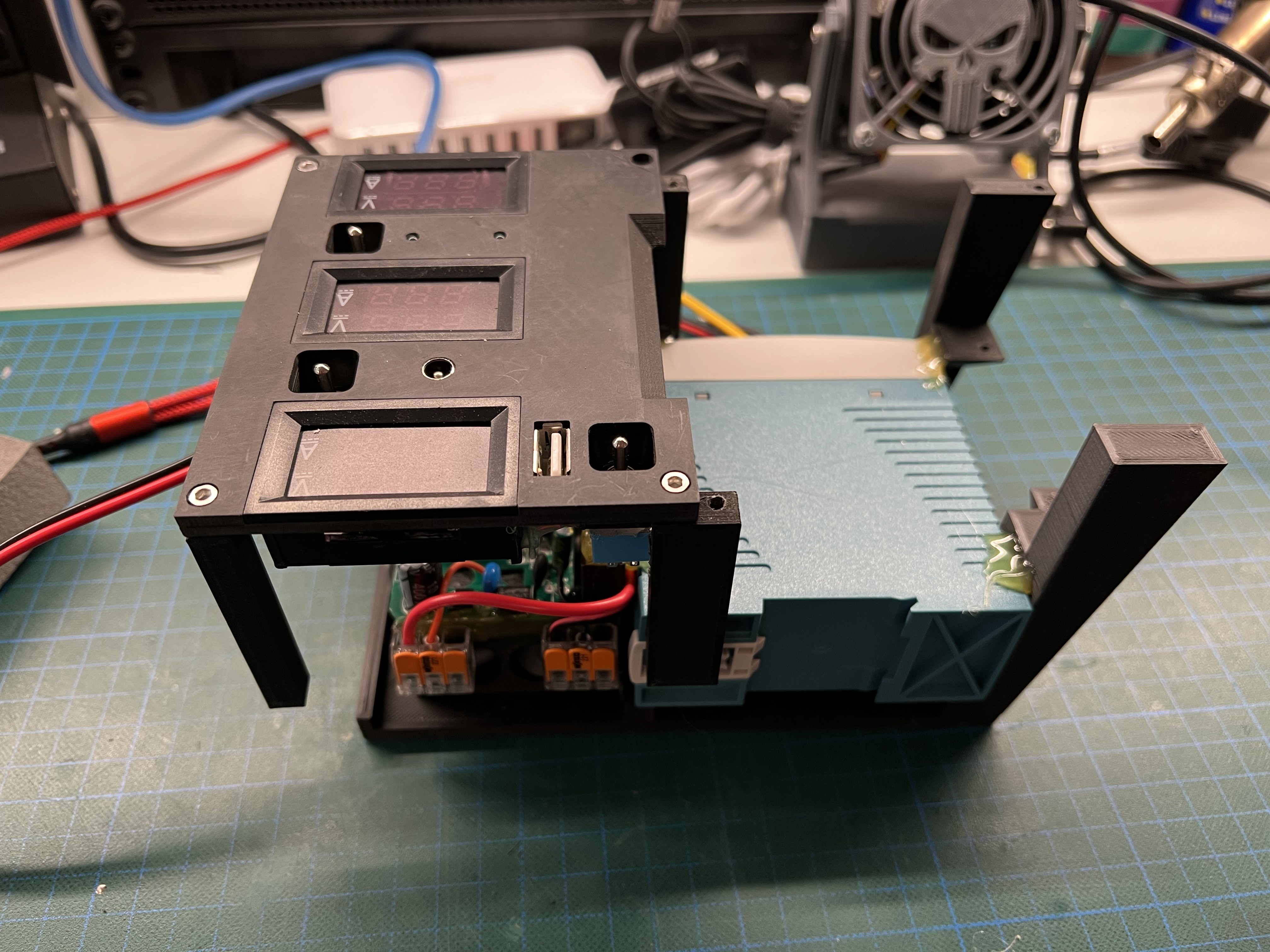
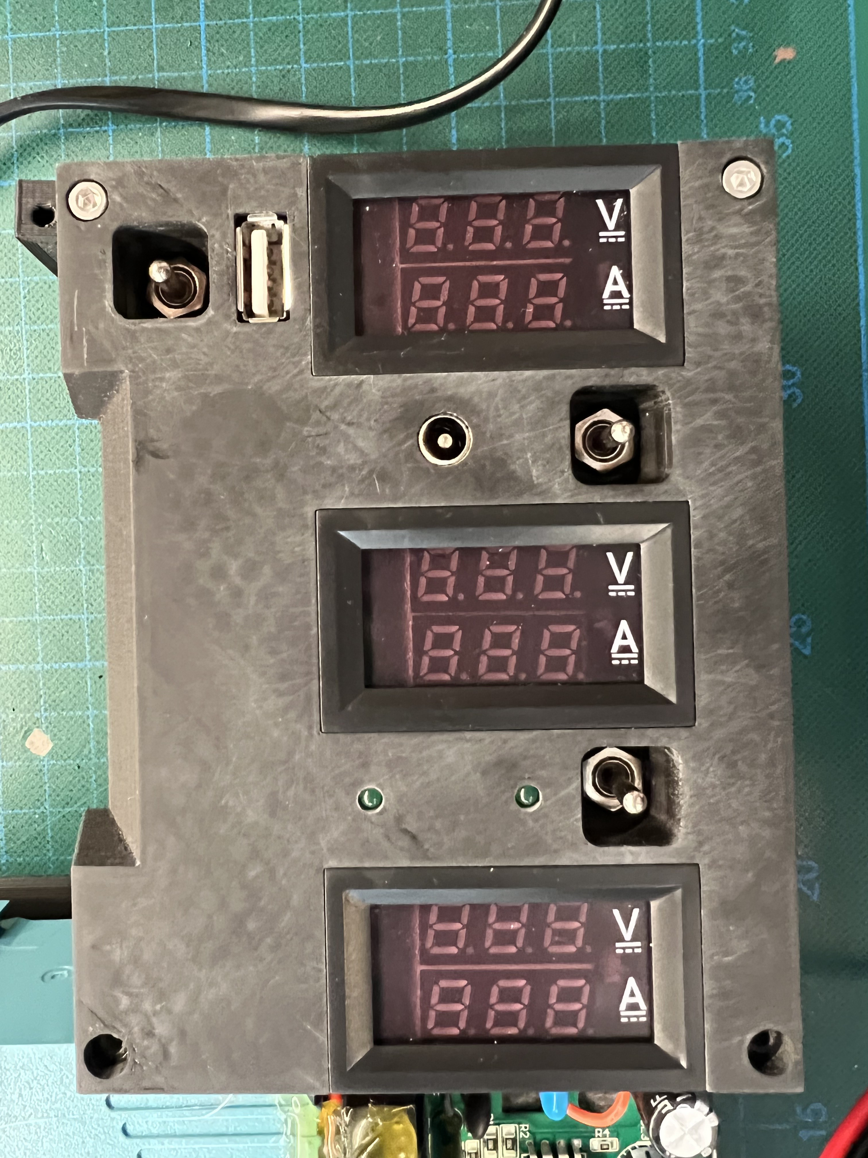
  • Module N - Power Switch Panel (DONE)
    • 2-Position Switches (ON/OFF - Left to Right)
      • 1: Module A
      • 2: Module B
      • 3: Module C
      • 4: Module D
      • 5: Module E
      • 6: Module G
      • 7: Module H
      • 8: Module I 
      • 9: Module L
      • 10: LTE/WLAN Router (hidden under Module Q)
      • 11: FireTV Stick (hidden under Module Q)
      • 12: Module P
    • 3-Position Switches (ON/OFF/ON - Left to Right)
      • 13: Switch to select the Power Source for Switches 1..12 (USV or 12V-5V Converter C)
      • 14: Switch to select the Power Source for the Monitor/Module Q (USV or 12V-5V Converter B)
      • 15: Switch to select the Power Source for the RasPi4 (USV or 12V-5V Converter A)
    • USB Socket (for external Power Sources, like an USB Power Bank)
    • Status LED (USV / External Power) 
  • Module O - UNUSED
    • Placeholder for another module in the future.
  • Module P - Alexa (DONE)
    • Amazon Echo Flex (brutally stripped down to the bare minimum)
    • P1: Audio Output of Raspberry Pi4 (for 3.5mm mini stereo jack plug)
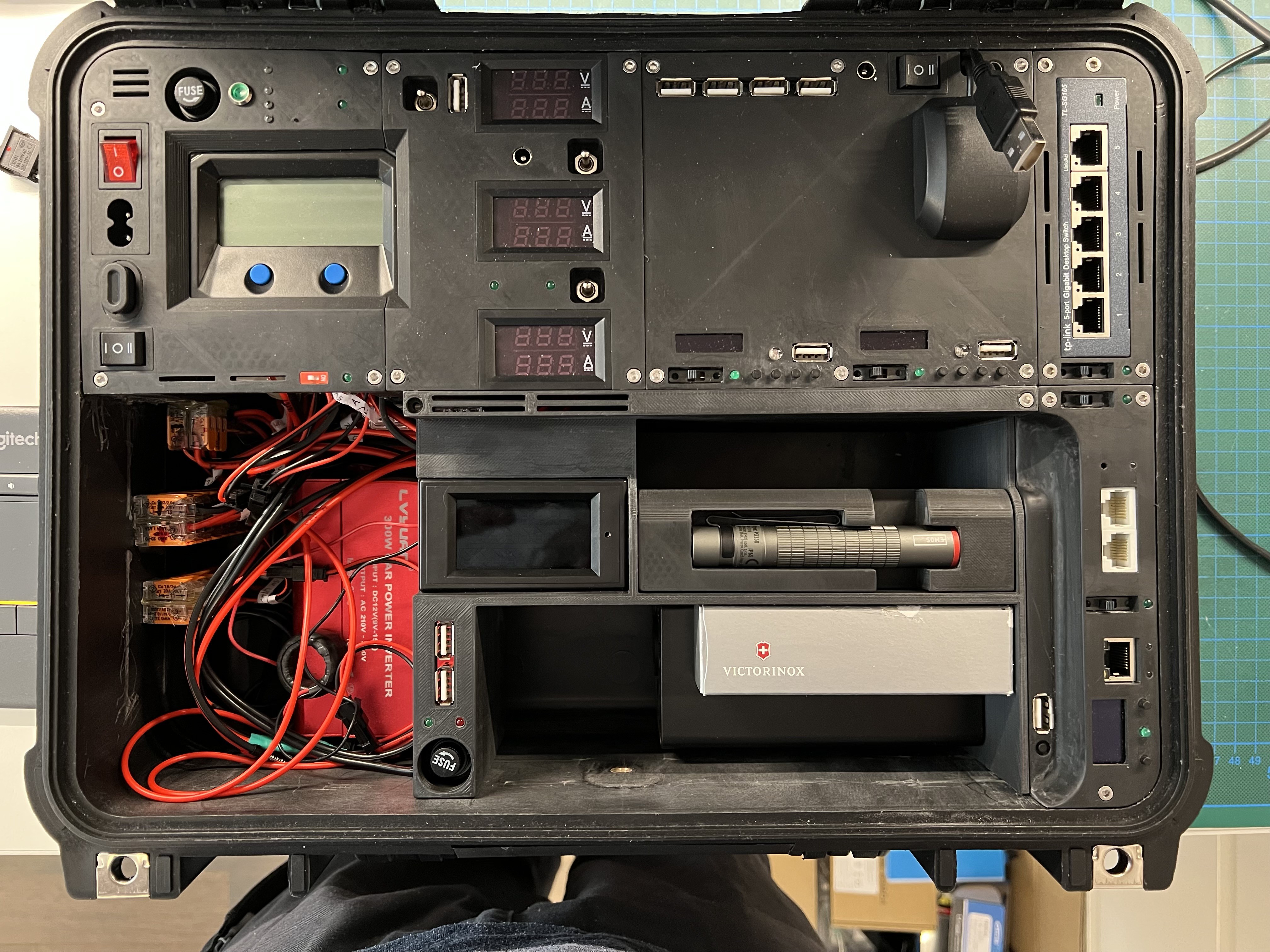
  • Module Q - 10'' Monitor (DONE)
    • HDMI input #1 for the RasPi4 (auto select)
    • HDMI input #2 for the FireTV Stick (auto select)
  • HIDDEN (behind Module Q)
    • Raspberry Pi 4
    • 5-Port USB 3.0 HUB
    • FireTV Stick...
Read more »

JPEG Image - 231.15 kB - 09/03/2022 at 14:20

Preview
Download

JPEG Image - 10.28 MB - 09/02/2022 at 22:34

Preview
Download

JPEG Image - 5.91 MB - 09/02/2022 at 22:34

Preview
Download

View all 70 components

  • The best companion for a Cyberdeck: Victorinox - Cyber Tool L

    Lord Of All Things09/07/2022 at 17:00 0 comments

    One of the best pocket knifes for the digital age and a great companion for my Cyberdeck: Victorinox - Cyber Tool L (no affiliate link, just my humble personal opinion!)

    Picture Source: https://www.victorinox.com/us/en/Products/Swiss-Army-Knives/Medium-Pocket-Knives/Cyber-Tool-L/p/1.7775.T 

  • The Black Beast Feature List

    Lord Of All Things09/07/2022 at 12:28 0 comments

    The Black Beast Feature List from A .. Z 

    0..9 ======================================

    • 433 MHz Analyzer/Sniffer -> Top Case / Module B (WiP)
      • which can detect and decode existing 433 MHz signals (e.g. decode a Weather Station)
      • which can transmit recorded or predefined 433 MHz signals (e.g. open a Garage Door)
      • which could be used as a 433MHz Yammer
    • 868 MHz Analyzer/Sniffer -> Top Case / Module C (WiP)
      • which can detect and decode existing 868 MHz signals (e.g. HomeAutomation / AskSinAnalyzer)
      • which can transmit recorded or predefined 868 MHz signals 
      • which could be used as a 868MHz Yammer
    • 125KHz & 13,4MHz RFID Reader / Writer -> Bottom Case / Module 18 (WiP)
      • which can read and write RFID Tags
    • 5V Power Supply -> Bottom Case / Module 12
      • which can be used to power or charge any USB device
    • 12V Power Supply -> Bottom Case / Module 15
      • which can be used (with the included adapters) to power any external 12V device (e.g. Ham Radio)
    • 230V Power Supply -> Bottom Case / Module 22e
      • which can be used to power any 230V device (300W max)

    A ========================================

    • AA / AAA Batteries -> Bottom Case / Module 24 (DONE)
      • 5x AA Rechargeable Battery (NiMH 1,2V)
      • 4x AAA Rechargeable Battery (NiMH 1,2V)
      • 4x AAA Battery (1,5V)
      • which can be used for the wireless Keyboard, Geiger Counter and Radio
      • which can be charged with the Battery Charger (Module 23a)

    B ========================================

    • Bluetooth Receiver -> Top Case / Module D (DONE)
      • which can be used to receive Stereo-Audio signals from a Bluetooth Transmitter (e.g. music from a Smart Phone) which then can be used (with the help of some Audio Spiral Cable) as Input for the
        • RasPi 
        • FM Transmitter
        • Bluetooth Transmitter
    • Bluetooth Transmitter -> Top Case / Module E (DONE)
      • which can be used to send Stereo-Audio signals from the following devices to a Bluetooth Receiver (e.g. Headset, Speakers, ...)
        • RasPi Audio-Out
        • Alexa Audio Out
        • FireTV Audio Out
        • Bluetooth Receiver Audio Out
    • Bluetooth Analyzer/Sniffer -> Top Case / Module G (WiP)
      • which could be used 
        • to intercept and decode Bluetooth Messages
        • as a PaxCounter (count all BLE devices in your neighborhood)
        • as an active BLE / iBeacon
        • as a Bluetooth Yammer
    • Battery Charger -> Bottom Case / Module 23a
      • which can be used to charge any of the following:
        • LiPo: 18650, 18490, 18350, 17670, 17500, 16340, (RCR123), 14500
        • Ni-MH/Ni-CD: AA, AAA
    • Ballpoint Pen -> Bottom Case / Module 26 -> as part of Victorinox Cybertool
    • Bottle Opener -> Bottom Case / Module 26 -> as part of Victorinox Cybertool
    • Blades (small, big) -> Bottom Case / Module 26 -> as part of Victorinox Cybertool
    • Bit Key / Holder -> Bottom Case / Module 26 -> as part of Victorinox Cybertool

    C ========================================

    • Carbon Monoxide Sensor -> Top Case / Module I (WiP)
      • via MQ-7
    • Digital radio Clock -> Top Case / Module J
      • battery powered
      • synchronized by the CF77 long wave transmitter in Mainflingen near Frankfurt am Main (Germany)
    • Combination Pliers -> Bottom Case / Module 26 -> as part of Victorinox Cybertool
    • Corkscrew -> Bottom Case / Module 26 -> as part of Victorinox Cybertool

    D ========================================

    • Dosimeter -> Bottom Case / Module 24 -> SOEKS 01M PRIME
      • radiation dosimeter that measures dose uptake of external ionizing radiation
    • DAB+/FM RDS Receiver -> Bottom Case / Module 25 -> August MB225

    E ========================================

    •  Electronic Field Lab -> hidden...
    Read more »

  • The Modular Concept (explained)

    Lord Of All Things09/07/2022 at 11:24 0 comments

    When the first ideas for this Cyerdeck came up, I was already sure to create it modular, as much as possible. As such I had defined the following requirements for myself:

    All "Modules" 

    • MUST
      • be easily replaced for future improvements, modification or maintenance reasons
      • be easy to assemble and disassemble (also in the field) using on-board tools (e.g. with a Victorinox - CyberTool L)
      • be connected with the Cyberdeck Base-Frame only by standardized connectors (e.g. JST SM)
      • be able to be switched on and off separately (by a dedicated switch).
    • SHOULD
      • be connected with the Cyberdeck Base-Frame only by one JST SM connector
      • only require 5V and less than 200mA
      • have a decentraliced Power-Switch plus Power-Indicator-LED
      • not just be designed to be physically assembled and disassembled in the field, but also provide an option to be easily re-programmed in the field. As such all Modules (at least if they have their own "Brain"), should provide a USB-Socket to connect its "Brain" (e.g. ESP32) to the RasPi (via the USB Hub and a USB spiral cable) and reprogram it using the Arduino IDE (installed in Kali Linux).
      • provide hidden (only accessible when disassembled) maintenance information (like PINOUT Plans, Passwords, ...). This could be done using small laminated notice boards or NFC tags.
    • COULD
      • have (as less es possible) additional, but standardized connectors for optional HW, like connecting external Antennas, Ethernet Cables, ...
      • be replaced by same sized "alternative" Modules, to fit different Use-Case-Scenarios in the field
    • WON'T
      • be clued or permanently connected to the Cyberdeck Base-Frame
      • be standard components (which you can buy), but totally overengineered custom-made Cyberdeck pieces!

    Below you can see the "WLAN Router / Network Analyzer" Module, which is just connected to the Cyberdeck with 3 Screws and 1 JST SM Power connector (5V). As you can see, the Victorinox - CyberTool is perfectly able to disassemble the module also in the field. This module is heavily packed with several components (incl. a brutally stripped down TP-Link TL-WR802N), making use of fiber-optics to route hidden "Status Led Information" to the front panel of the Module ... and it contains a hidden AirTag to track the location of the Cyberdeck.

  • Electric Wiring of the Top Case

    Lord Of All Things09/03/2022 at 14:22 0 comments

    Here is the electric Line Diagram of the Top Case, incl. 15 Switches to route the energy to the desired device(s).

    • The 12V Input is connected with the 12V Output of the Bottom Case.
    • Depending on the amount of activated devices (and power consumption) in the Top-Case, the build in USV can autonomously provide the necessary power for quite some time.
    • Optionally an external 5V Power Source can be connected (e.g. a powerful Power-Bank)
    • As a result, the Top-Case is de-facto completely de-coupled from the Bottom-Case and brings its own redundancy and internal Power Source (USV)

    SOME KNOWN PROBLEM & INSIGHTS 

    • Sadly (even if the specification of the Step-Down Converters tell something different), the Step-Down Converters are sometimes not able to provide a stable Voltage and/or current. As such, specifically in Battery Mode (12V Provided by the Bottom-Case), the RasPi sometimes reboots. Wen the Cyberdeck is connected with 230V or a strong PowerBank, this does not happen. As such I am still experimenting with suitable Step-Down converters.
    • Instead of a 60W 5V and a 10A 12V Power Supply in the Bottom-Case, I should have used just a powerful 12V Power Supply to save some space for additional gadgets!
    • The additional Power Supply for the RasPi Peripherals (all the USB 3.0 HUBs + connected USB devices) currently is for sure somehow unconventional... As soon as the RasPi is powered by the Switch #15 it will close the Relais and the Peripherals are power supported by a 2nd Step-Down Converter. Without, no chance to power up the RasPi in the Cyberdeck at all (with the current Step-Down Converters).
    • Sadly the USV is good for all internal devices (1 ... 12) and the Monitor or the RasPI, but not fall all. It does not provide enough current and voltage stability. How ever, the very flexible "routing" of the energy with the Switch Panel allows plenty of options to by-pass or compensate this. And remember: It is not intended to have the RasPi powered up all the time. In a lot of use cases you don't need it (e.g. when you make use of some of the ESP32 Modules, or the LTE/WLAN Module in combination with the FireTV Stick or the Echo Flex).

  • Electric Wiring of the Bottom Case

    Lord Of All Things09/02/2022 at 22:11 0 comments

    On request: Here is the electric wiring of the bottom case. As you can clearly see, I'm neither a good draftsman, nor have I drawn the electrical components in accordance with the "rules". Anyway, I hope this sketch can shed some light on the wiring of the electrical components.

    The electric wiring for the Top Case will follow soon ...

View all 5 project logs

  • 1
    The Case

    It all started with the following case

  • 2
    The 3D Files

    Although some may think I'm crazy, I have completely designed the Cyberdeck using Tinkercad. I know there are way better tools, but I am used to Tinkercad and considered it an additional fun challenge to just use a basic 3D design tool ;)

    Here you can find the parts for the Cyberdeck - Top

    Here you can find the parts for the Cyberdeck - Bottom

  • 3
    The badly documented assembly process of the bottom part

    1.) It all started with the assembly of the top-right router and the bottom-right Wifi & Network Analyzer Module

    2.) The bottom-right Wifi & Network Analyzer Module (I have stripped the TP-Link WLAN Router like hell and used a lot of Hot-Glue)

    3.) Next was the 12V Battery and its RFID / NFC cover

    4.) Followed by all the Power Modules & Volt Meters, ...

    5.) ... and a first test run

    6.) Assembly of the modular "Boxes" part

    6.) And the final status of the bottom case

View all 5 instructions

Enjoy this project?

Share

Discussions

music_man32 wrote 02/02/2023 at 21:43 point

I really like this build and really interested in how you created the GPIO status indicator panel? I've been trying to work out how to build something like this for a raspberry pi 4. 

It's an inspirational project you've created and great notes. Thank you for sharing. 

  Are you sure? yes | no

Turkish1450 wrote 01/27/2023 at 20:10 point

Can you explain your thought process around component placement? I have far less things to pack in my build at this point but I have a bit of analysis paralysis. My big issue is designing the mounting and I don't see any particular standardization in your build that would allow for moving things around.

  Are you sure? yes | no

Gregi wrote 12/11/2022 at 23:26 point

Survived machine should have a lighter (something like this -

ARECTECH Lighter Electric Lighter). Will you implemented it too?

  Are you sure? yes | no

Nicolas Tremblay wrote 11/09/2022 at 15:15 point

Wow!
Just incredible the amount of functionality you packet in this beast. Most battle-stations/lab don't have most of this stuff. Great luggable.

  Are you sure? yes | no

Turkish1450 wrote 10/13/2022 at 14:39 point

Maaaaaan. I didn't need a new project but this is sweet. I love how much you packed in there. Have you done any testing to see how long an "average" runtime would be on that battery?

  Are you sure? yes | no

Lord Of All Things wrote 10/13/2022 at 17:59 point

I haven’t done any runtime testing yet, as I am still experimenting with different voltage converters. If we are talking about the Raspi + Monitor + all peripherals, I assume it will be at least 4-5h. If the Monitor and/or Raspi is not in use, it might be way more (most likely days). It’s hard to answer, as the power consumption is really depending on the use case and active modules. However, what I had in mind for the unused module slot was, to have some Arduino Nano and some current/voltage sensors, that could provide a forecast (on a small display) for the remaining battery life in % and time …

  Are you sure? yes | no

Turkish1450 wrote 10/13/2022 at 19:02 point

Fancy. I like that idea.

  Are you sure? yes | no

Charles Stevenson wrote 09/26/2022 at 00:08 point

It is a beast!

  Are you sure? yes | no

odin conner wrote 09/13/2022 at 18:06 point

how much is the total cost for the components

  Are you sure? yes | no

Lord Of All Things wrote 09/13/2022 at 18:52 point

Mhh … I never calculated the total costs, but I assume it’s ~ 500€/$. 

  Are you sure? yes | no

odin conner wrote 09/13/2022 at 19:41 point

well goodbye to my money

  Are you sure? yes | no

Frank wrote 09/02/2022 at 18:41 point

LOAT, 

I really like this build, this and another CD are what I am using for inspiration for  my build. 
I am building a spreadsheet of my power loads, and was wondering what the consumption of your screen is? Do you have a 1 line diagram of your power? 

  Are you sure? yes | no

Lord Of All Things wrote 09/02/2022 at 18:53 point

Hi Frank,

thx for your feedback! I will measure the consumption of the screen and create a basic wire diagram and provide both tomorrow …

  Are you sure? yes | no

Lord Of All Things wrote 09/02/2022 at 18:58 point

The Screen takes 560mA at 5V

  Are you sure? yes | no

Frank wrote 09/02/2022 at 19:12 point

Thanks, that isn't bad at all. I have another question. You have an ethernet switch in the top right, how do you connect it internally? Or is it not? I was looking at using something like this, so 4 ports are exposed and one can be connected internally to a CM4 based router

https://www.alibaba.com/pla/5-port-switch-module-PCB-board_1600091839363.html?mark=google_shopping&biz=pla&pcy=US&searchText=Switch+Module&product_id=1600091839363&src=sem_ggl&from=sem_ggl&cmpgn=15581229768&adgrp=132611869873&fditm=&tgt=pla-1082573610178&locintrst=&locphyscl=9030099&mtchtyp=&ntwrk=u&device=c&dvcmdl=&creative=569900552593&plcmnt=&plcmntcat=&p1=&p2=&aceid=&position=&localKeyword=&pla_prdid=1600091839363&pla_country=US&pla_lang=en&gclid=Cj0KCQjw08aYBhDlARIsAA_gb0dNGQ05qpyTCFH1WfJdCcr1Syww41igiF15MLZaiKOJXEs34yOJnnUaAv4jEALw_wcB

Great work all around. Easily one of the best looking CDs I have seen.

  Are you sure? yes | no

Lord Of All Things wrote 09/02/2022 at 22:25 point

Hi Frank,

as you can see in the Project Log, I have uploaded two pictures of the power line diagram for the bottom case. The one for the top will follow soon. 

Wrt to your router question: This is a TP-Link TL-SG105 5-Ports Gigabit Switch, which has no ports at the bottom, but just the 5V Power connector. As you will see in some pictures I will release this weekend, it is intended to connect this Switch (on demand) with 15cm Cat6 Patch Cables to the other devices in this deck (which could be the RasPi4 or the LTE WLAN Router in the Top Case or the 2nd WLAN Router or Network Analyzer in the Bottom Case) or any external network devices. In my opinion, that provides much more flexibility, especially in cases where the RasPi4 is not needed at all.

  Are you sure? yes | no

Tom Nardi wrote 08/25/2022 at 18:03 point

This is a very impressive build, love how much hardware you've managed to pack into it. Are you going to be adding any images of the internals? I'd love to see how it's all put together.

  Are you sure? yes | no

Lord Of All Things wrote 08/25/2022 at 21:08 point

Hi Tom,

I will definitely add some more details, pictures and STL files later this week. So stay tuned ;)

  Are you sure? yes | no

Similar Projects

Does this project spark your interest?

Become a member to follow this project and never miss any updates