 Tinfoil_Haberdashery
OVERVIEW
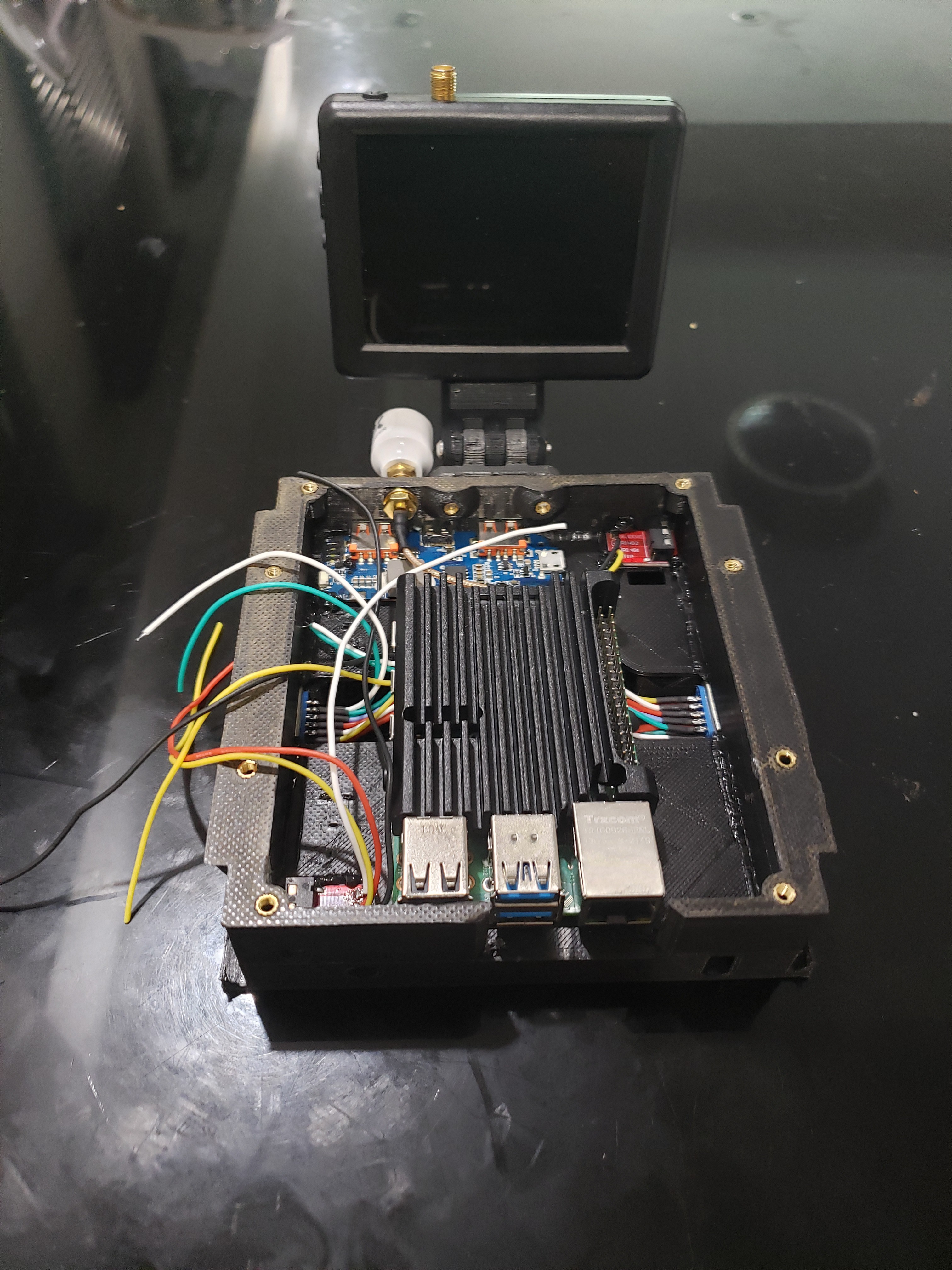
This project is a modular Raspberry Pi-based cyberdeck that builds upon the "detachable module" concept that I explored with my original Ulfberht+ Cyberdeck. However, instead of a simple detachable half-keyboard that connects with an exterior TRRS cable, this project seeks to have multiple interchangeable modules with a wide variety of functions. These modules will connect to the "core" in a structurally robust manner with a highly-versatile data port integrated into the locking mechanism.
MODULE SYSTEM
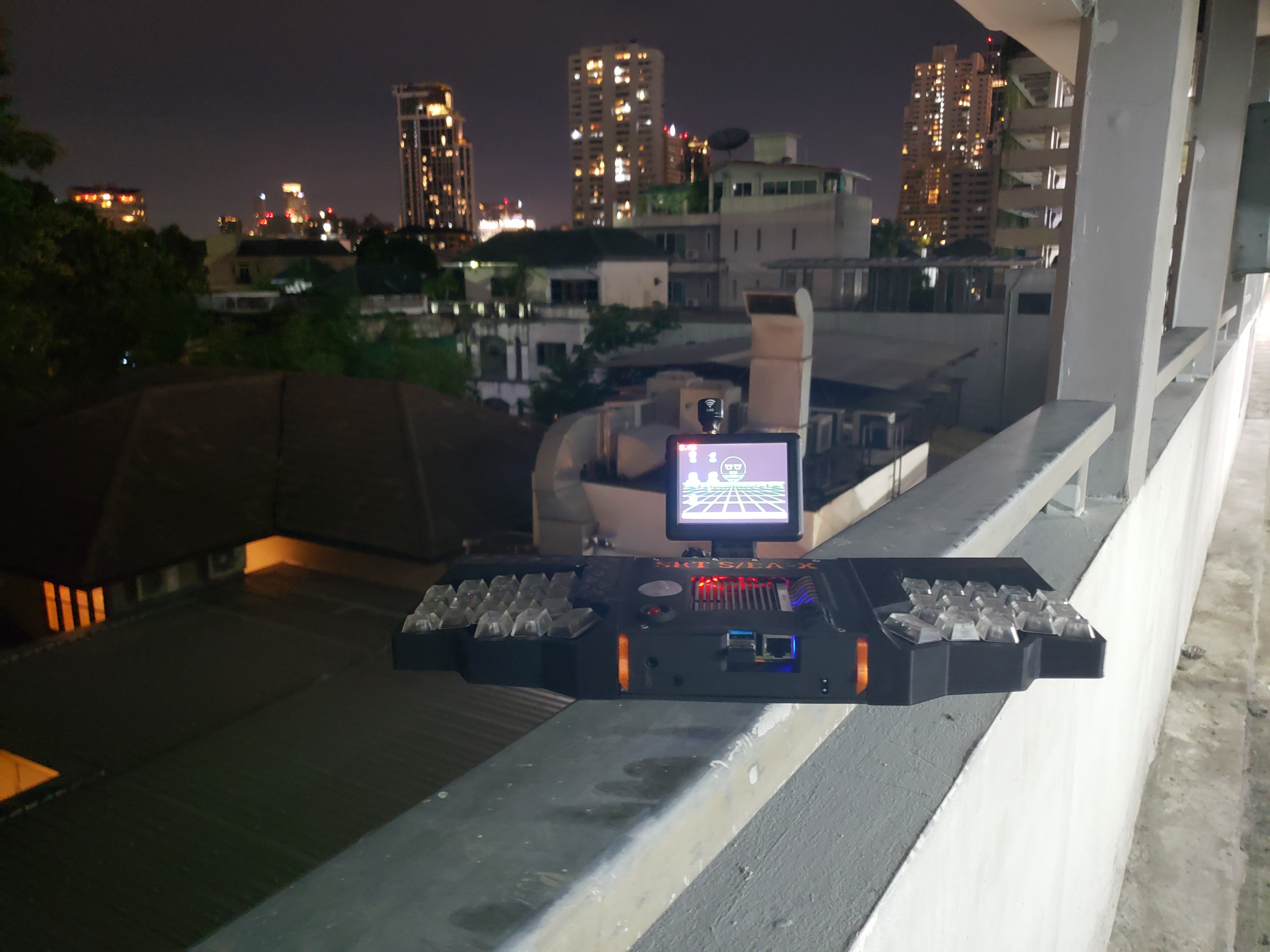
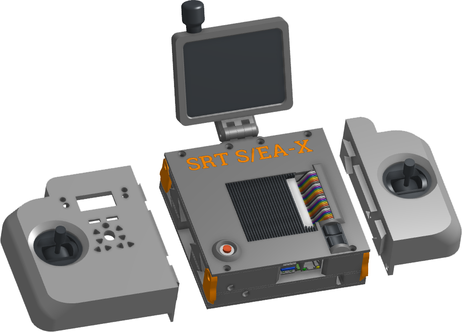
These modules include (at the time of publication), split keyboard halves, two halves of a radio control transmitter, and a software-defined radio receiver.
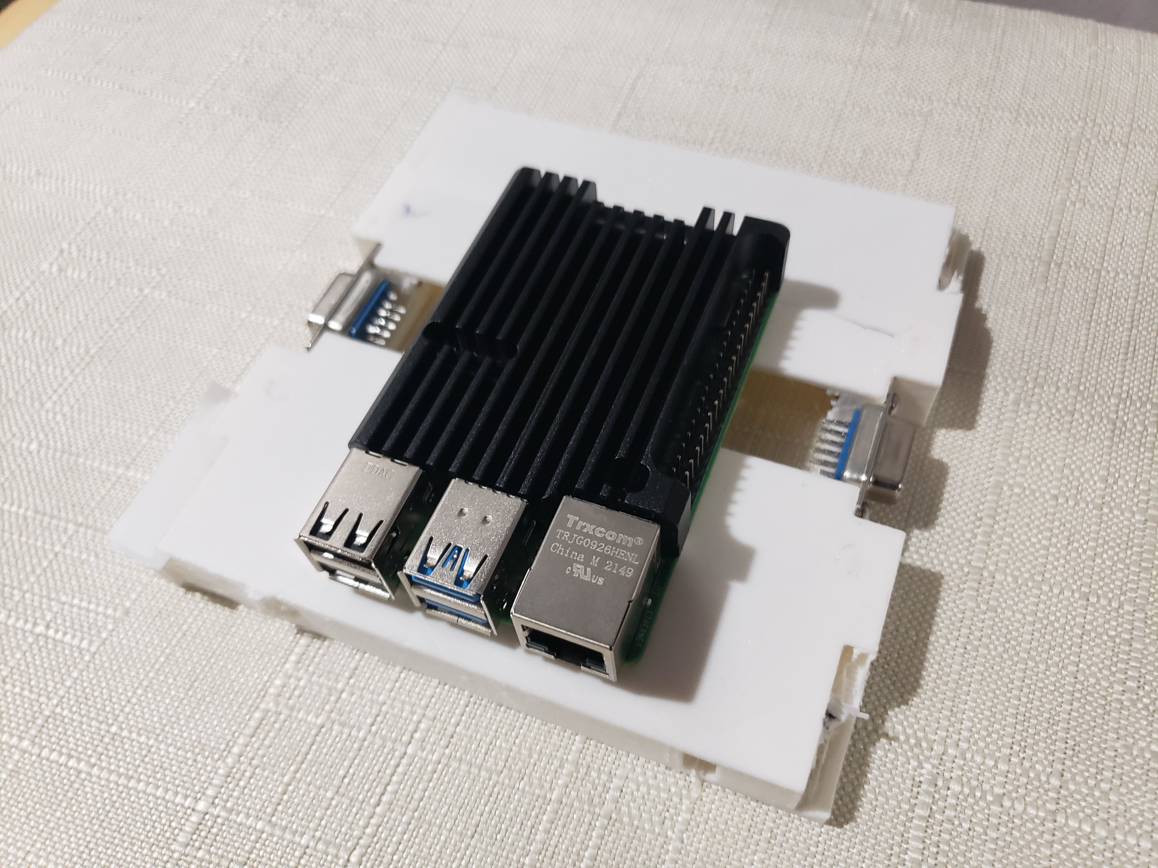
The core module contains the pi and provides 5v, cell voltage, USB2.0 data, and several "passthrough" conductors that allow two modules to communicate directly with each other, to accommodate, for example, the connection between two halves of a split keyboard, or to pass signals from the gimbal and switches on the righthand RCTX split module to the main board in the left-hand module.
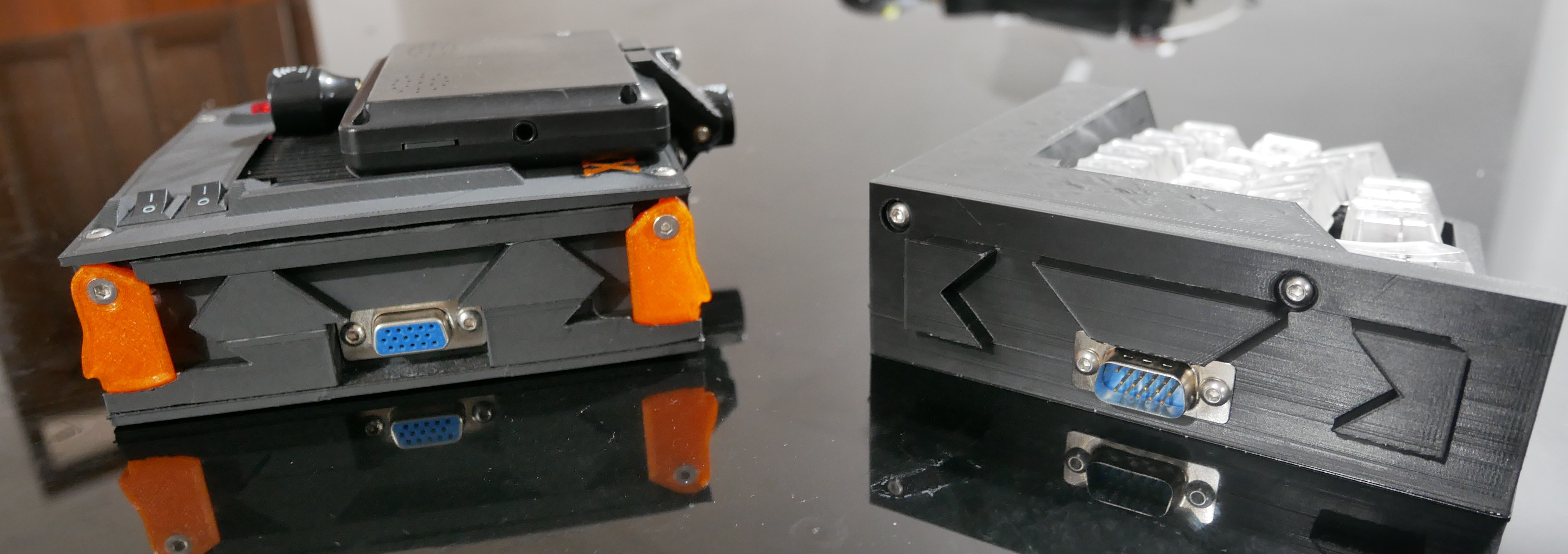
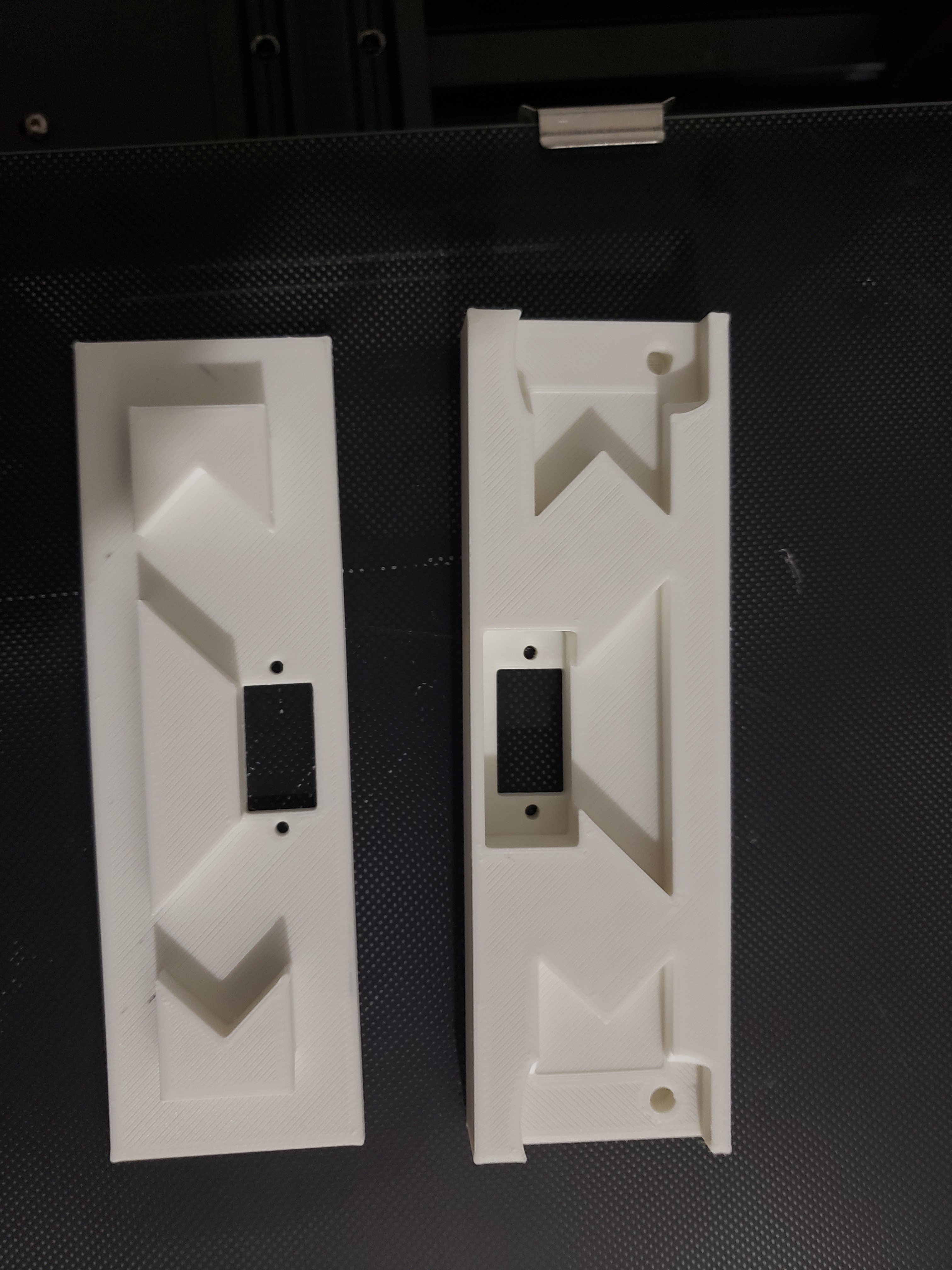
The structural connection uses multiple tapered tenons that interlock with mortises in the other half. This allows for a high degree of precise indexing and rigidity with relatively loose tolerances suitable for 3D printed parts. The modules are locked in place by two cams (orange) which capture the tapered back edges of the outer tenons.
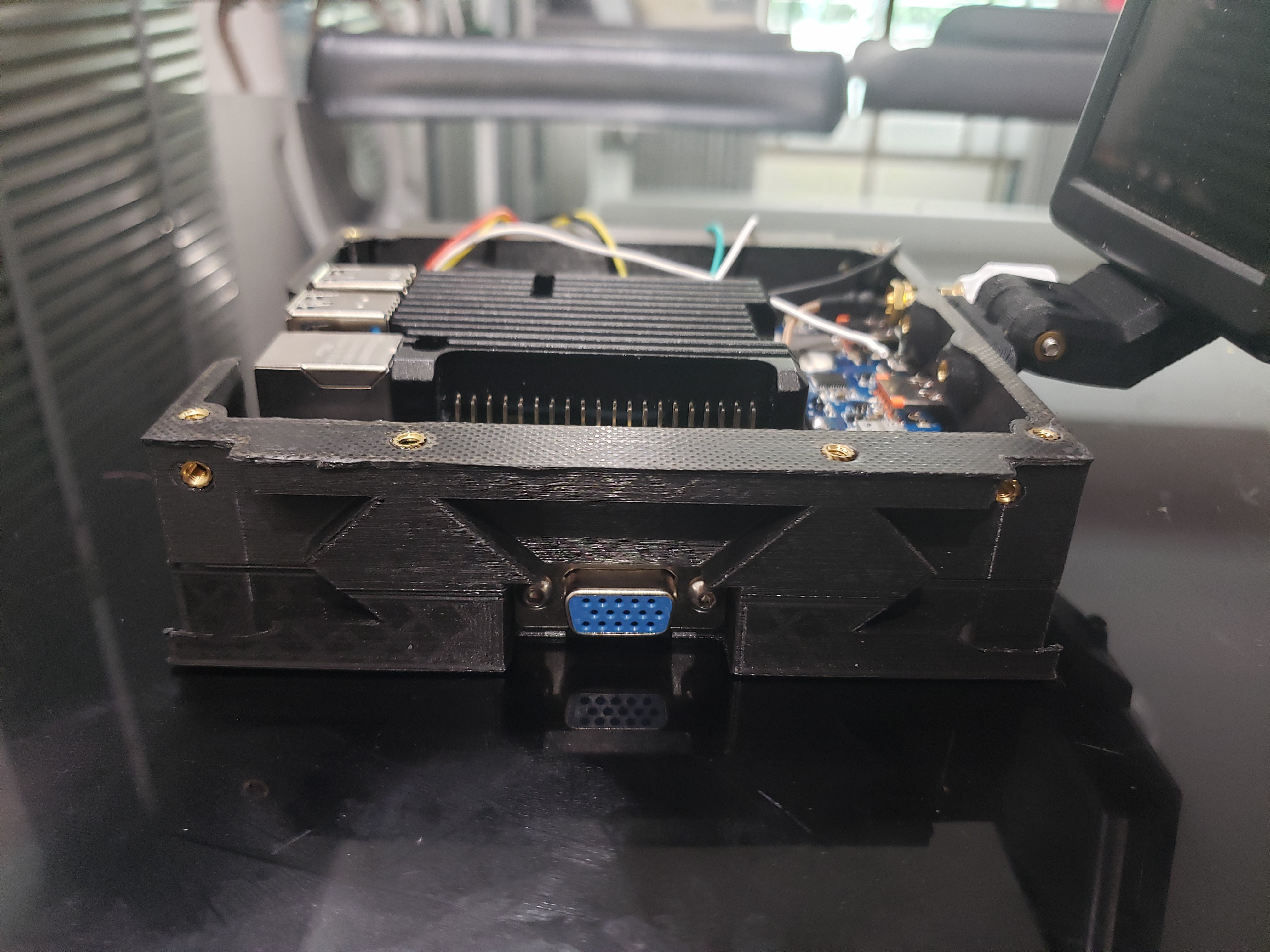
The electrical connection is accomplished with a 15-pin DSUB connector, ubiquitous as the standard port for VGA. This provides a large number of parallel connections in a compact, cheap, easily-sourced part. It will also allow modules to be connected via a cable instead of directly to the device, for things like split keyboard configurations, using only a cheap and ubiquitous VGA cable and a gender-swapper.
In addition, modules can be designed to be "intermediate" or "terminal", depending on whether they have one or two connectors. So, for example, one can put the intermediate software-defined radio module intermediate between the core and the righthand RCTX module.
Planned modules currently include:
- Game controller
- Trackball
- Battery expansion
ADDITIONAL CORE FEATURES
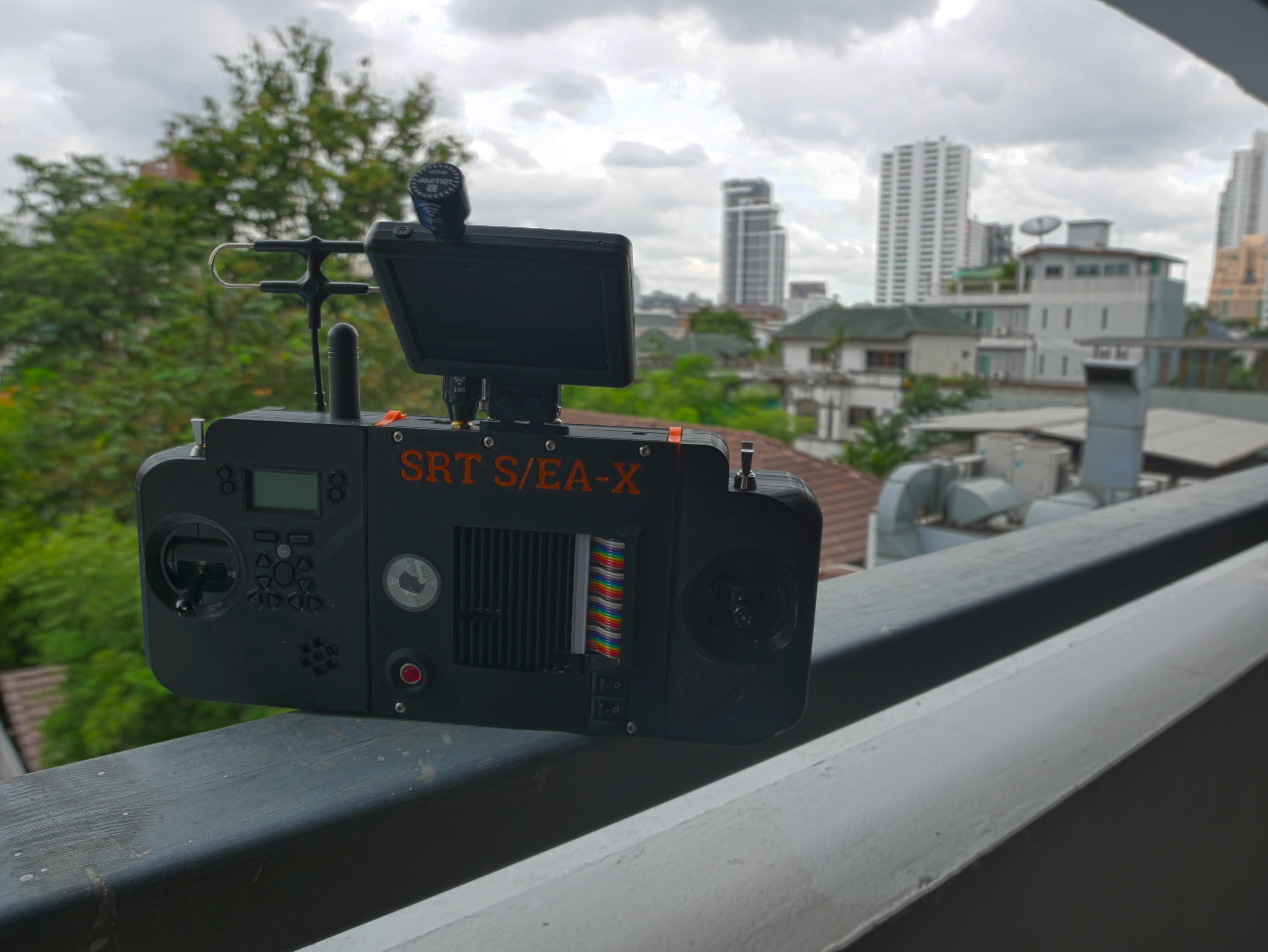
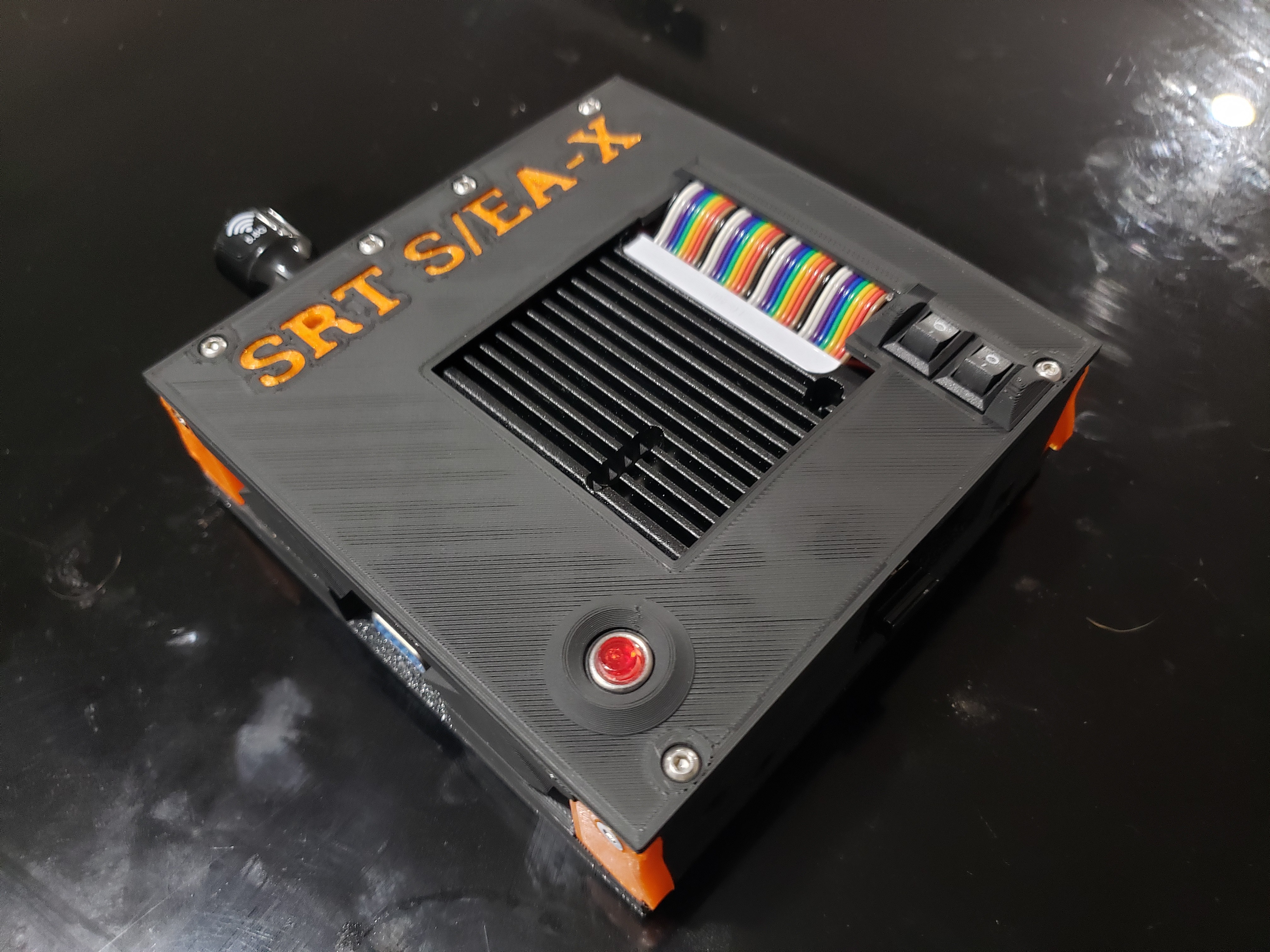
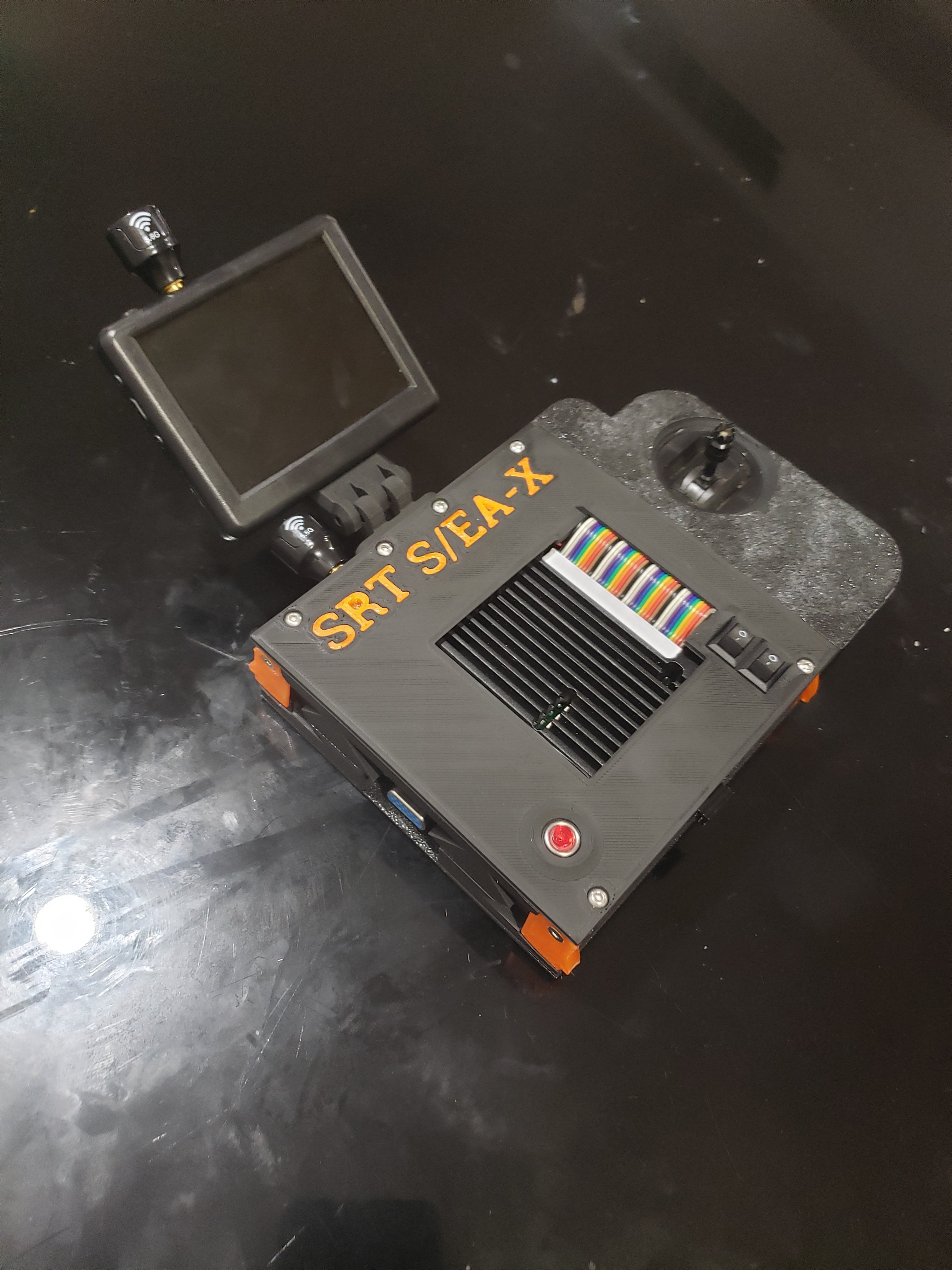
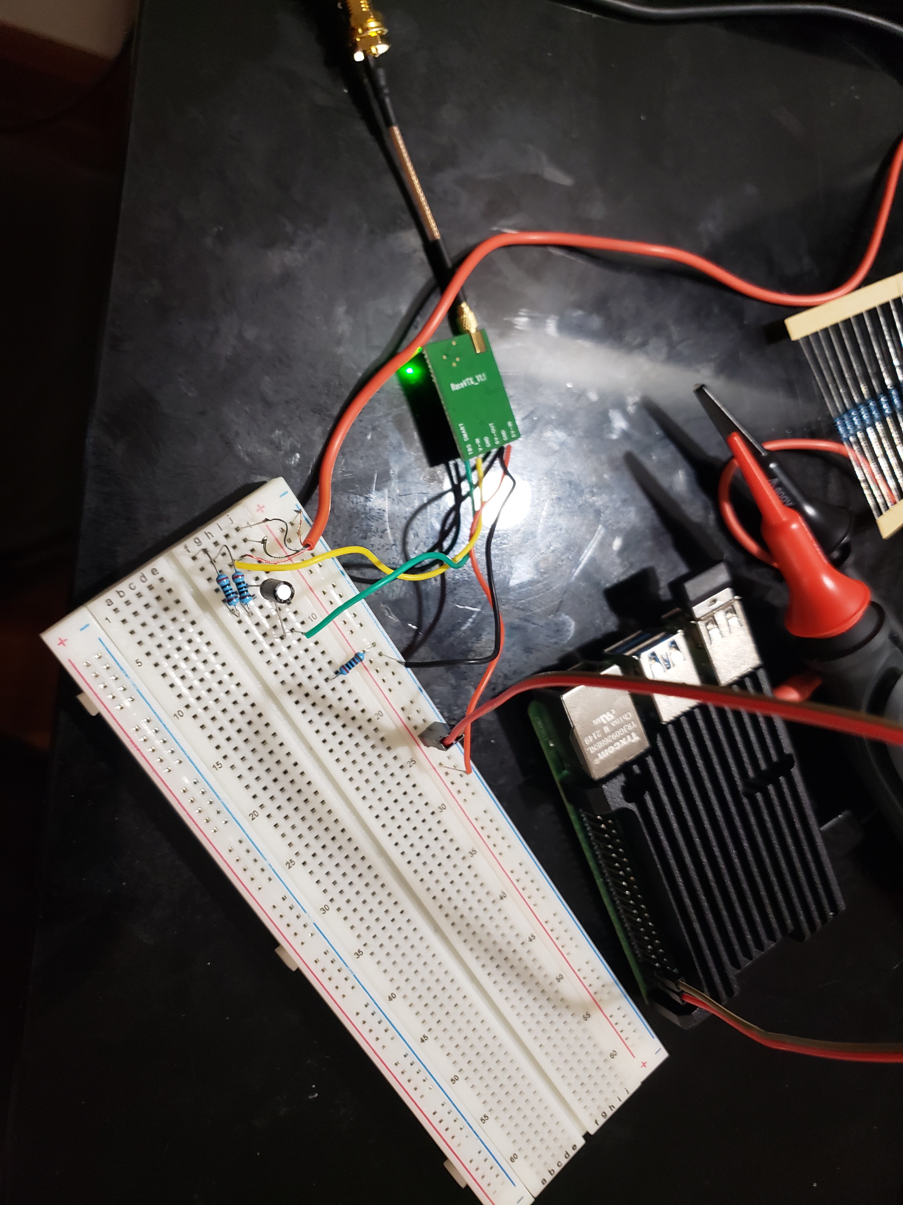
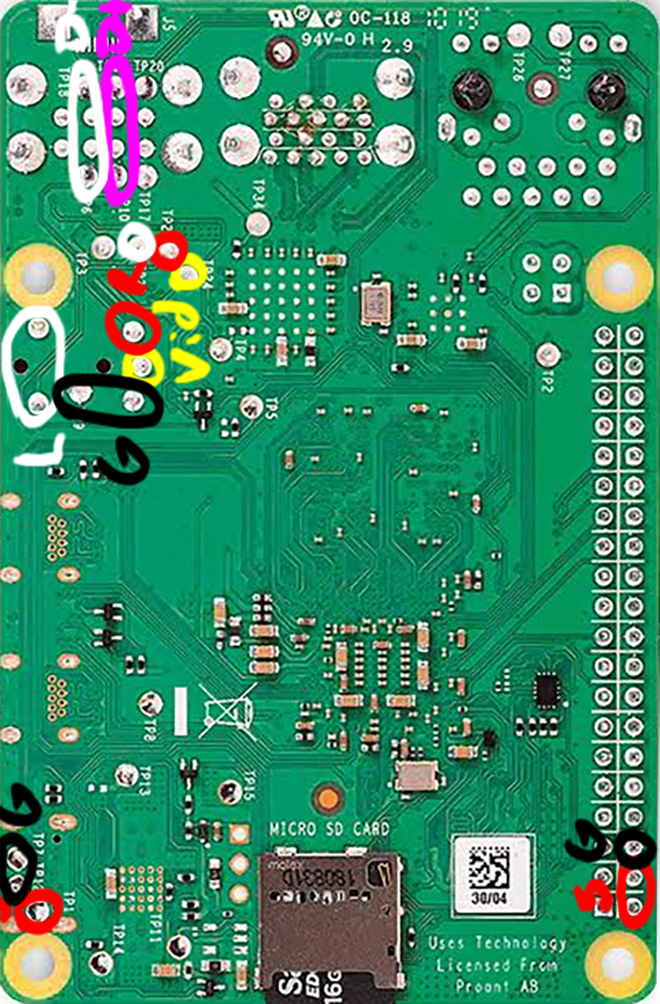
The core of the device contains several key features of the design, including wireless audio/video output over 5.8ghz, allowing remote operation with goggles or various screens. Hard-wired composite video and audio ports are also included on the shell of the device for low power, low EM noise, and more consistent video quality.
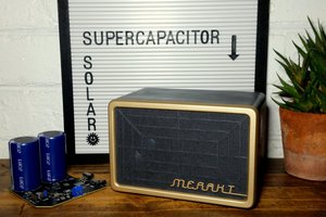
Additionally, the device contains a high-capacity 37 watt-hour battery which provides power not only to the core, but also to any external modules. Such a large-capacity battery would take 4-6 hours to charge over a standard USB connection, so multiple charging options are provided for, including USB fast charging and wide-voltage DC input up to 36v, for charging rates of up to 20 watts and power sources ranging from other computers to car cigarette lighters to portable solar panels, as well as straight connection to a dedicated lithium battery charger at up to 37 watts for 1-hour turbo charging.
PURPOSE AND FUNCTIONALITY
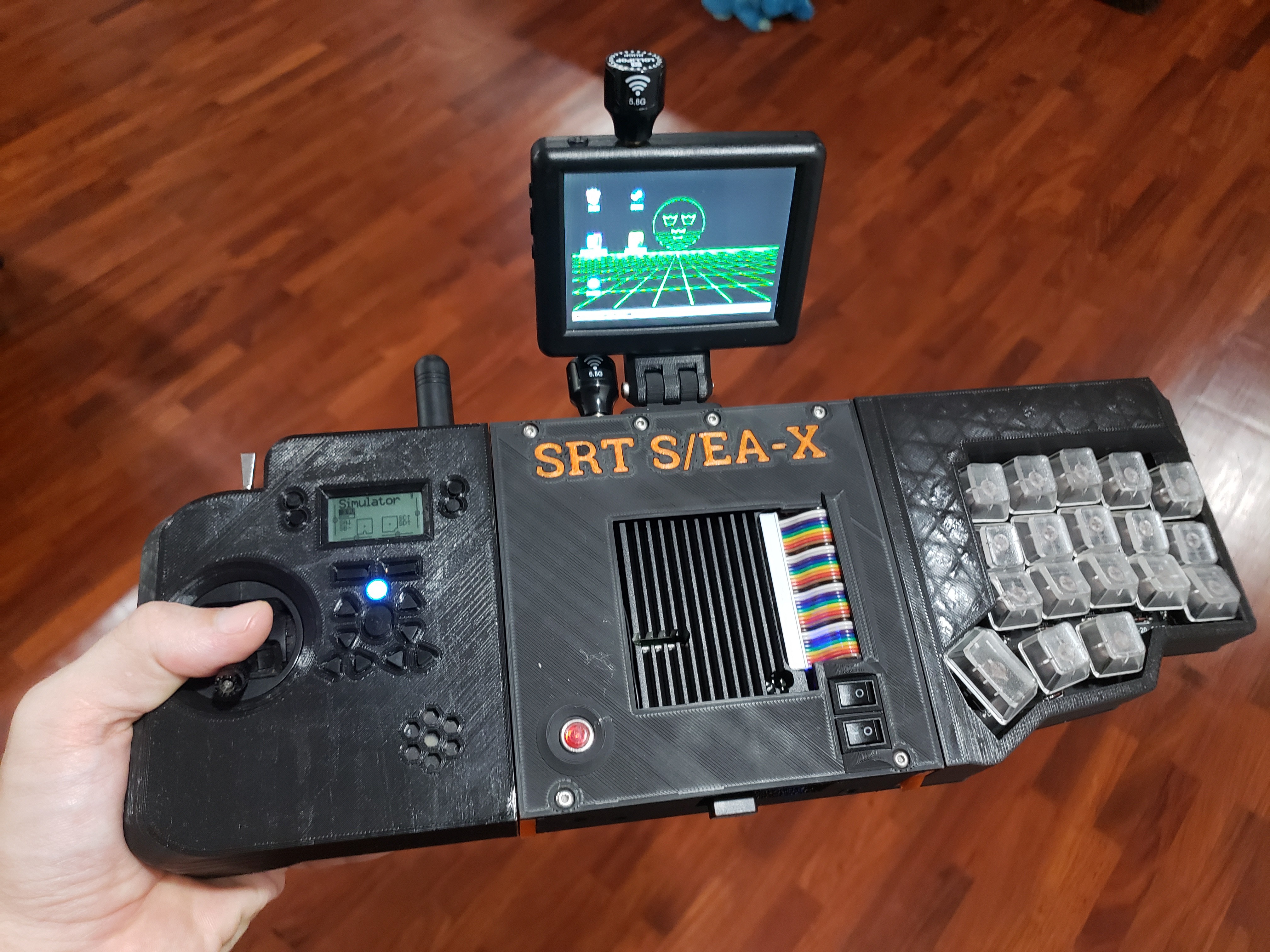
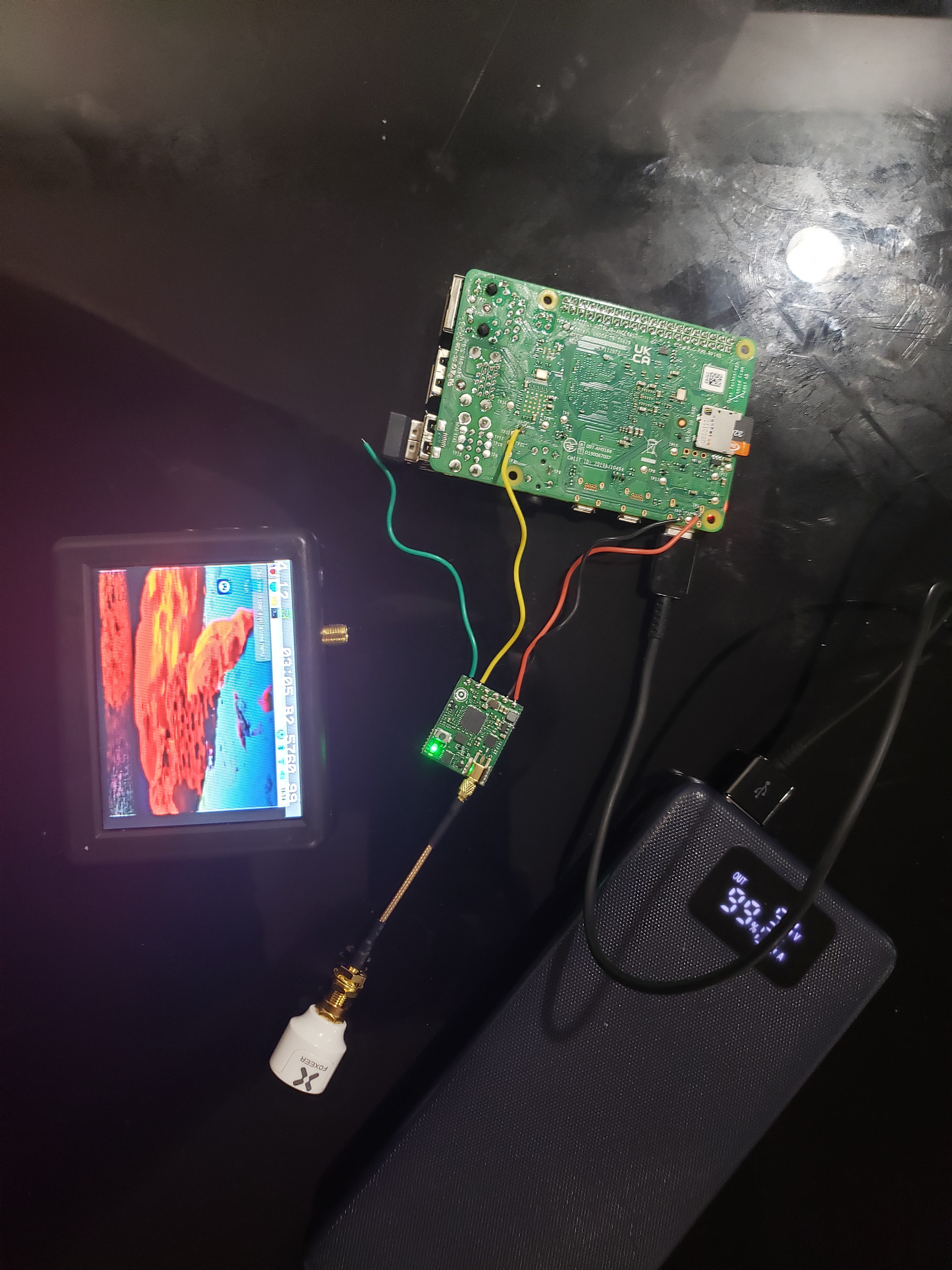
This is meant to be as multi-functional as possible; that said, the initial purposes for which its modules are field tuning of FPV drone flight tuning and using the SDR for monitoring the AirBand for manned air traffic.
Additionally, this system works (albeit with more latency than would be preferred) to practice FPV flight using Steamlink to connect the controller to a more powerful computer and pass video back to the actual FPV screen or goggles.
Additionally, the long battery life, compact size and ability to transmit wirelessly to a head-mounted display make it excellent for writing or other computing in unconventional settings (read: I can write or watch youtube in bed without annoying my partner. Truly, we live in a cyberpunk future).
Does it work in this configuration? Of course not. But it sure...
Read more »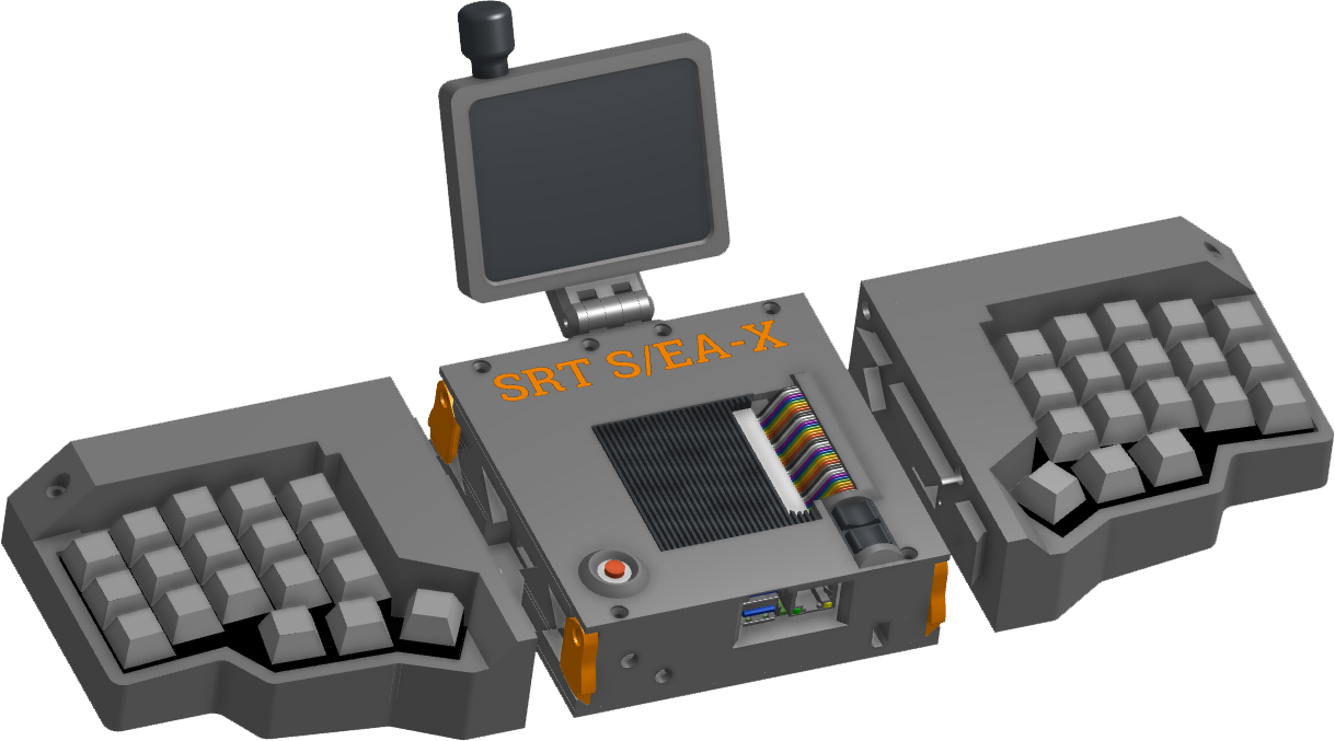


 Jamie Matthews
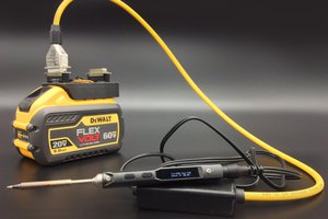
 William
 Dan Julio
Great project, Kelly watching it coming along. I'm glad to see someone else soldering to the bottom of the board. I didn't realize the pi4 still supported composite.