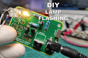
DIY GUY Chris
Tools that you will need
Probably you will need some electronics designing and assembly skills in this project if you are willing to build your customized Stepper Controller similar to mine, but you still can use the ready made A4988 shield along-side with some other on breadboard and it will perfectly work.

So in case you will make your ow Stepper Controller then you will need some Supplies for the Software and the Hardware, here I list them both:
- Software:
- Hardware:
Solder Paste CHIPQUIK SMDLTLFP10T5
In addition to the Printed Circuit Board and its electronics components which are listed in Step 3.
Details About A4988

Maybe you saw it somewhere but probably you didn't spotted these details, actually the name of the "A4988 Stepper Shield" firstly invented by inventors of Polulu Robotics & Electronics when first DIY CNC Machines appear since these Stepper drivers helps to easily driver the Steppers of CNC machines but the name itself comes from the Integrated Circuit of the Shield which is the A4988 designed and manufactured by British company Allegro Microsystems mainly oriented to Automotive industry sector.
The Shield is now a popular part among makers and even engineers since it is highly used in prototyping due to its high performance mainly coming from the A4988 IC.
This chip helps to drive a Bipolar Stepper Motor in full-, half-, quarter-, eighth-, and even sixteenth-step modes which gives high motion precision, it is also able to drive up to 2Amps per stepper coil at up to 35V DC which is very satisfying to drive several Stepper Motors Models.
You can find the full Part Datasheet by clicking this link.
In our project we will not consider Microstepping mode of this IC since the stepper will run in continous mode with adjustable speed and controlled direction.
It's Good to Make a Prototype

I will not immediately get to the Circuit board design but first it is always recommended to try your circuit on a breadboard as long as you have some ready made modules and then once it works without problems then you can transform the whole circuit from the breadboard into one Printed Circuit Board design so here we are.

I used the A4988 Module provided by Polulu and if you don't know how to properly interface with it then maybe you want to ready my posted instructable about it by clicking this link.

The circuit is mainly based on the signals coming from the NE555, I manage to generate a square wave form signal from this IC configured in Astable mode, the square pulses frequency will define the stepper rotation speed since this signal will go from the NE555 Output pin straight to the STEP pin of A4988 module, remember that the higher the signal frequency the faster the motor speed, I controlled the frequency of the output signal through a potentiometer acting as voltage divider on the THRES pin of NE555.

The main power input is 9V DC converted to 5V through a 7805 voltage regulator to get the appropriate logic voltage for the A4988, I place a slide switch on the DIR pin of A4988 module in order to control the motor direction, in such setup the pull-up high of the DIR pin will switch the Motor rotation direction.
From Breadboard to Circuit Board

Here is the advantage of this guide, I'm intending mainly to show you how you could produce your own customized circuit board design and put all the parts and components that you use from your prototyping breadboard in one circuit board design that you could take it to the market for selling (always good to make incomes pushing you forward in your invention journey).

I moved to Altium designer ECAD tool that helps me to put all the prototype blocks in one schematic and then transform the schematic into a PCB design to establish the nets connection of my blocks and this way I get the whole design in one circuit...
Read more »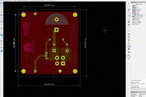
 Mark Rehorst