 Sagar 001
I am aware of sensors, modules and integrated circuit used with microcontrollers like Arduino. And I think Arduino UNO is still the first choice of most hobbyists even after 10 years. Because of its open-source environment and futuristic Software. Developers released some easy to program software’s for it. Arduino Uno is the first MCU of this series, you can see different variants with names on official website.
I am working with Arduino for a long time. And I know the communication protocols and hardware compatibility. Because Arduino is released in 2012 and getting more and more interesting day by day. But the design is same during this era butt I want to modify the design. Not because of any mistakes but due to compatibility issues.
1) Old USB type A, which is not used too much nowadays.
2) Power jack can be eliminated, because direct power system is more consistence.
3) Female headers are available in low number
4) 3.3volt can’t support more than 200mA
5) Not much use of ICSP headers.
6) Overkill circuitry.
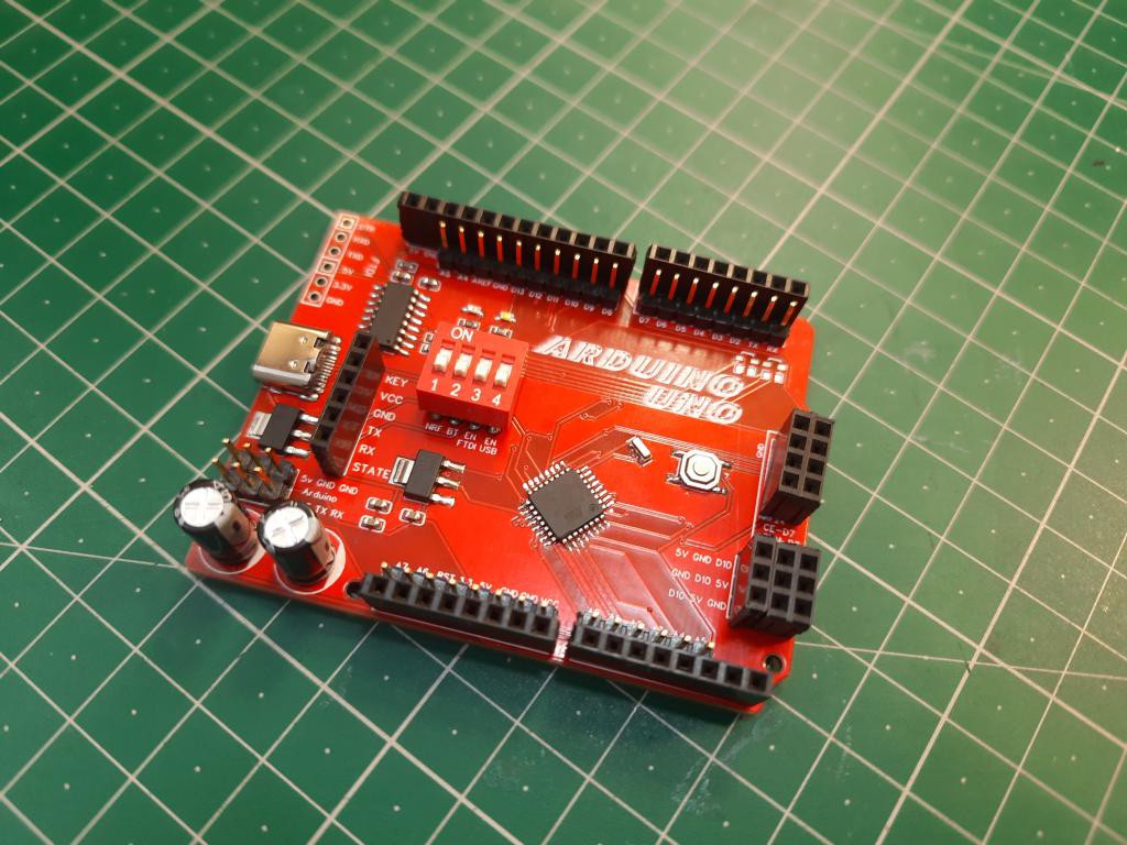
To eliminate these problems and to modify the overall layout I choose to make my own microcontroller development board which is fully compatible with UNO. Cost can be reduced using SMD components, using a low power USB to serial. And finally adding different ports/ headers for the widely used 12C modules, screens, Bluetooth, Radio modules and sensors.
Because I want to test my projects first on this Arduino so by decreasing the number of jumpers wires circuit become less complicated. And all of these things can be possible by using JLCPCB prototyping service. JLCPCB offers 5PCS of 2layer PCB in just $2. Register now to JLCPCB to get free coupons of worth $54. As for now you can get the required Gerber, BOM and CPL files only by messaging me on Instagram: Sagar_Saini_7294.
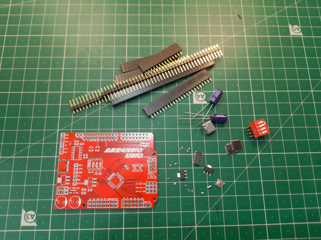
Components used:
- Atmega328p- SMD version
- 16 MHz SMD crystal
- CH340C USB to serial chip
- Type C Female USB
- 1K resistors
- 10K resistor
- 100nf capacitors
- SMD tactile button
- Blue and red SMD LEDs
- D
- IP switch x4
- Pin headers
- AMS1117 5v, 3.3v voltage regulators
- 100uf electrolytic capacitors
- Custom PCB from JLCPCB
Circuit diagram:
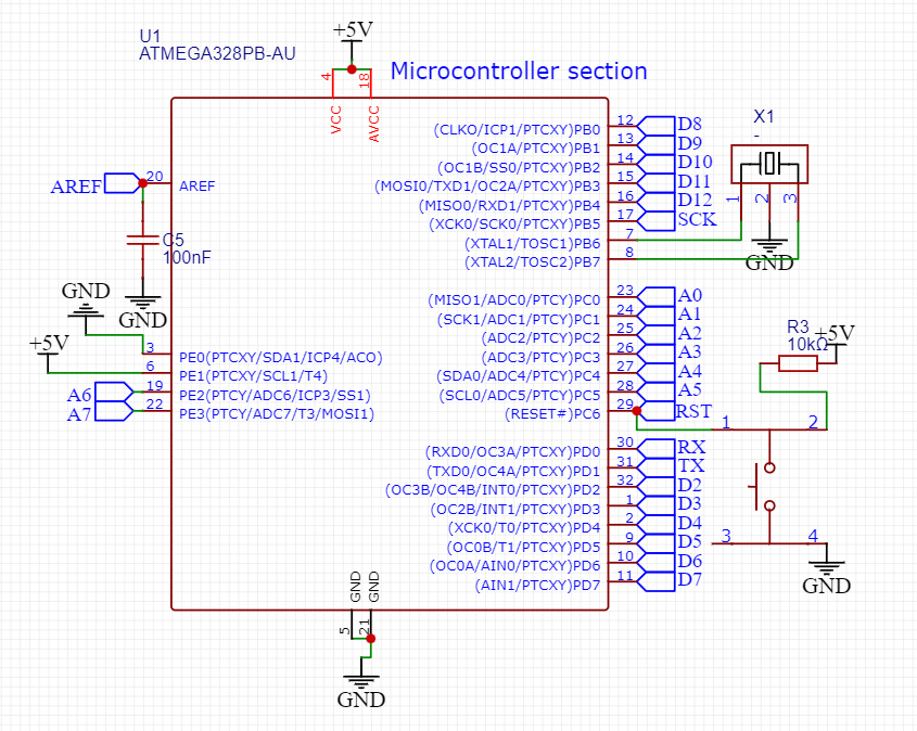
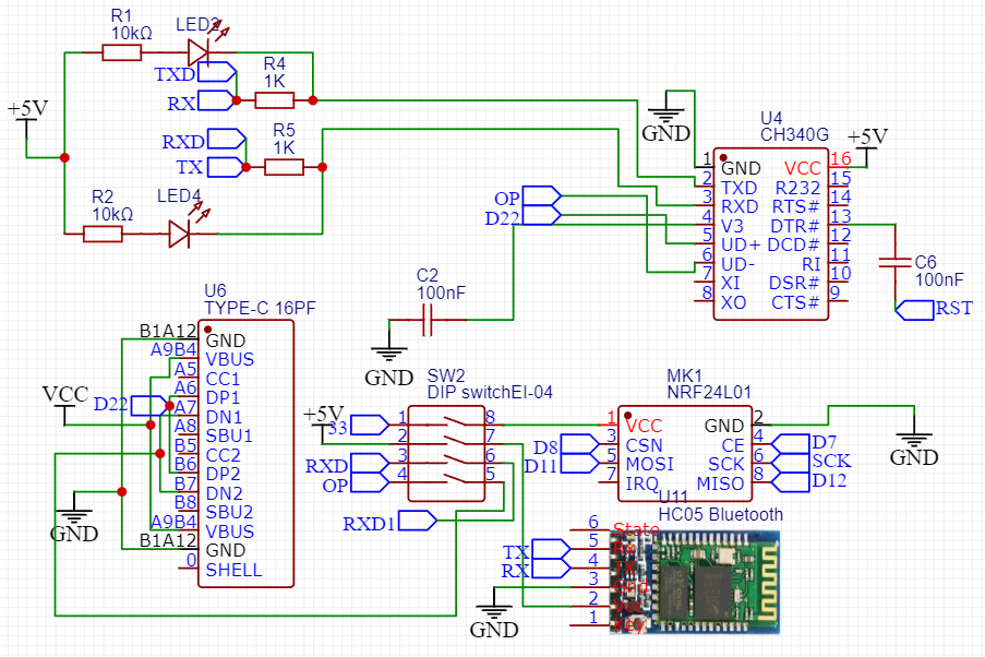
The circuit of this microcontroller is quite simple, just follow the basics of data structure and datasheet. I am using CH340C as the USB to serial programmer. This chip has many variants and I am using “c” which has internal oscillator of 12MHz. Blue LEDs are used for Tx and Rx pins and Orange and yellow for the power and D13 pin.
1K resistors are used with these LEDs for current limiting. AMS1117 5volt regulator provide +5volt to the whole board. 100nF and 100uf capacitors for noise reduction and power filtering purpose. Tactile button with 10k resistor completes the reset circuit. A new generation USB type C for better looks and strong connection. I used Different pin headers for the I/O pins, Bluetooth connection and 12C.
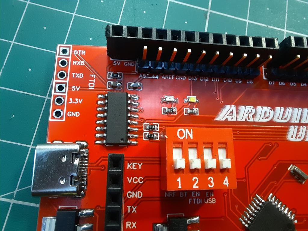
The FTDI, Bluetooth, radio and USB can be enabled using DIP switch mounted in between of the PCB. Actually, this is the main component which control the action of whole circuit.
Schematics Design and PCB:
I used EasyEDA to design the schematics of this board, there are many more features are added which are listed below in working section. If you want to modify the layout with the availability of components in your area then you can use EasyEDA and take reference as my design. The connections are okay and tested with proper net markings.
As for the PCB, I turned my schematics into PCB fabrication file. Then do some designing and place all the components at their place. Then I do manual routing of this board and download the project in the form of Gerber file.
You can upload this file to the PCB manufacturer to make a physical prototype. As for now you can get the required Gerber, BOM and CPL files only by messaging me on Instagram: Sagar_Saini_7294.
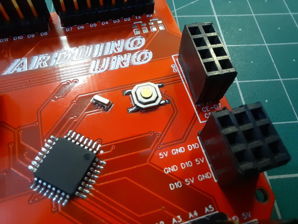
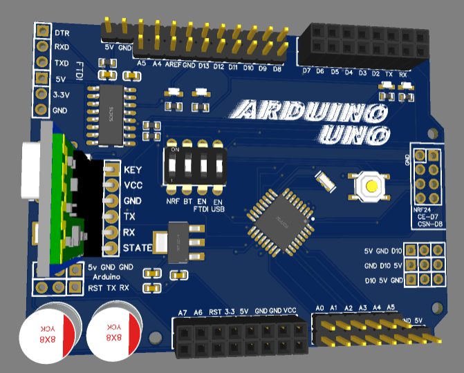
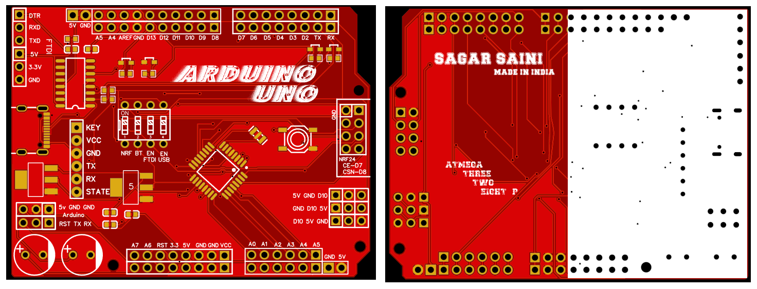
PCB specs and components mounting:
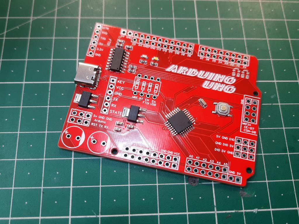
The assembly of component value is given in the picture, you can add resistor and capacitors according to that. Get me on Instagram to get the full schematics and all files.
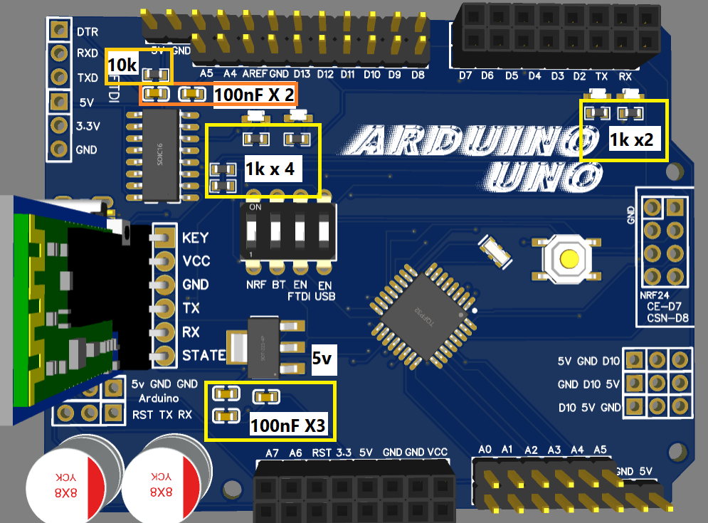
Here all the smd components like resistor, capacitors and LEDs are 0603 package. So, try to manage the same size as preferred or you can assembly service from JLCPCB that offer SMD assembly just in $8.
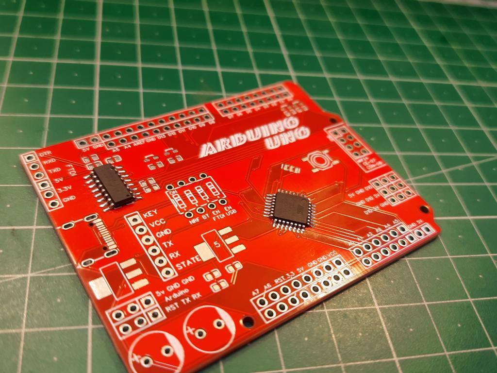
Assembling the PCB board:
It is very difficult to solder the SMD package of Arduino chip using simple solder, until you don’t know right method to solder.
Just solder one pin first and the add access solder paste get some solder wire on heated solder and make a layer through out the chip. Any short in the chip pins can be removed using solder wick.
It is always recommended to use excess solder paste with SMD, but clean the residue immediately after soldering.
First Power ON:
Check the power connection in continuity, if everything is okay then connect the USB power. If there is a beep then check the soldering connections. If there is any misconnection then resolder the component again. Most of the times there is short in USB type C connector or in SMD chip.
Burning the bootloader:
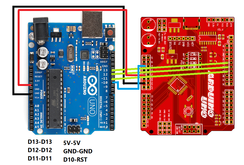
Before uploading any sketch to the Chip, you need to burn the boot settings to it. It can be done by simply using another Arduino UNO board. Upload the Arduino ISP code to the 2nd Arduino from the examples section.
Connect both the Arduino’s according to the given wire diagram. Then select the Programmers as ISP and click on burn bootloader. It will take a minute or less to burn the program successfully. After that you are able to upload any program to the chip. But I always recommend to go firstly with blink LED example.
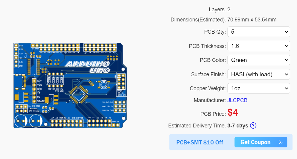
PCB files and testing codes:
I converted the schematics into the PCB and then into Gerber files. If my design seems interesting then get the Gerber files from me and upload them to JLCPCB offering 5pcs of 2-layer PCB in just $2. I used red solder mask, FR4 material, hasl finishing and 1.6mm thick PCB. You can download all the used codes from here.
Working and features:
1) FTDI mode:
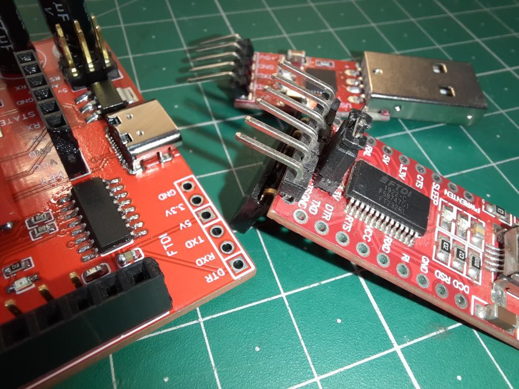
I added a FTDI features in this module, means if you want to program the any Arduino board like mini, Nano this can be directly connected to headers. No need of external programmer for that. Now you can switch between two modes of FTDI through DIP switch. 1St to program the onboard Arduino chip and 2nd to program any extremal MCU board.
2) Bluetooth:
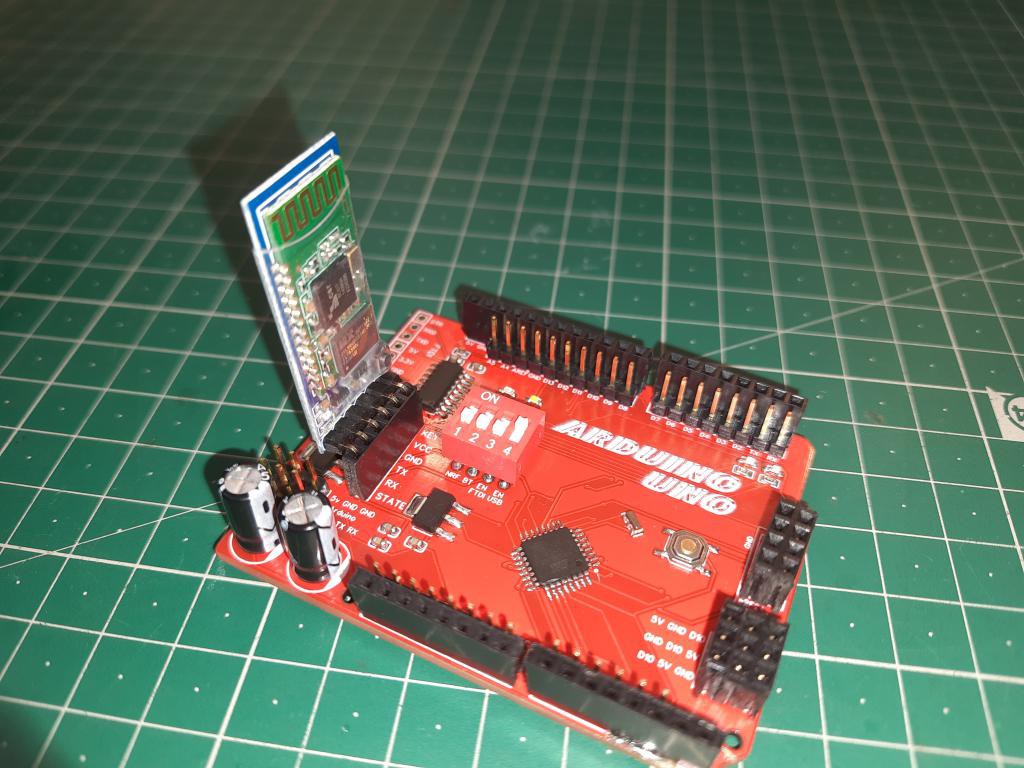
I also added headers for the Bluetooth module. Offers to program the board wireless over Bluetooth. But we will cover that feature in another article. This module uses Serial protocol for the interfacing. And same DIP switch is used to ON/OFF the module.
3) NRF24L01 Radio:
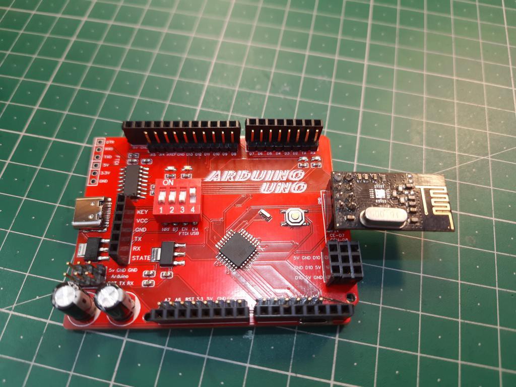
Nrf24L01 is mostly used with Arduino as remote-control purpose. I added headers of NRF to one side of my Arduino board so that the module can be directly plugged in to the headers. All the connections of wires are labelled on the Arduino board PCB sink screen layer,
4) 3X3 I/O header:
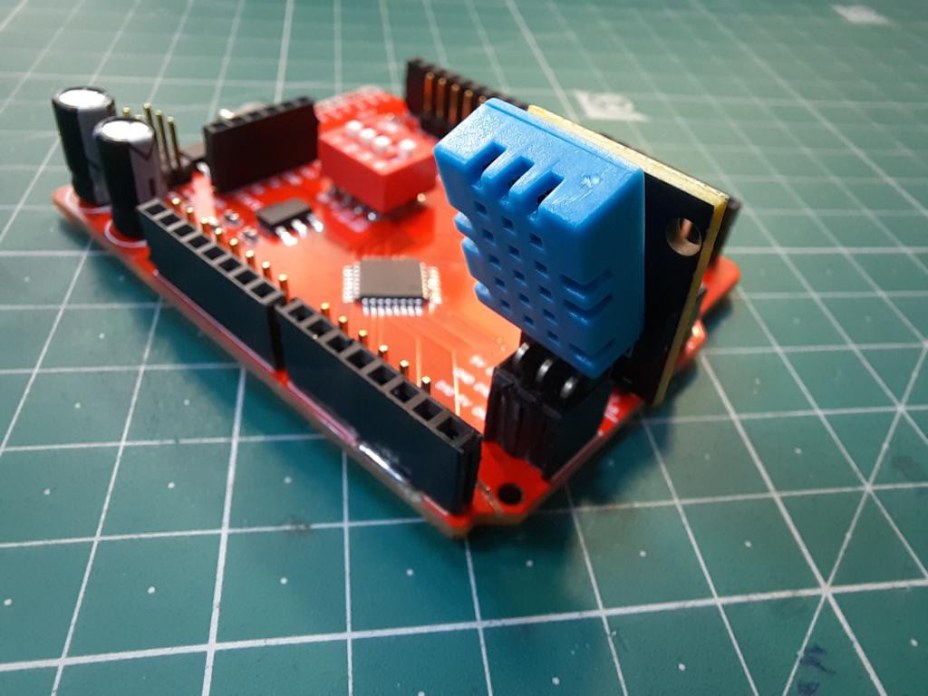
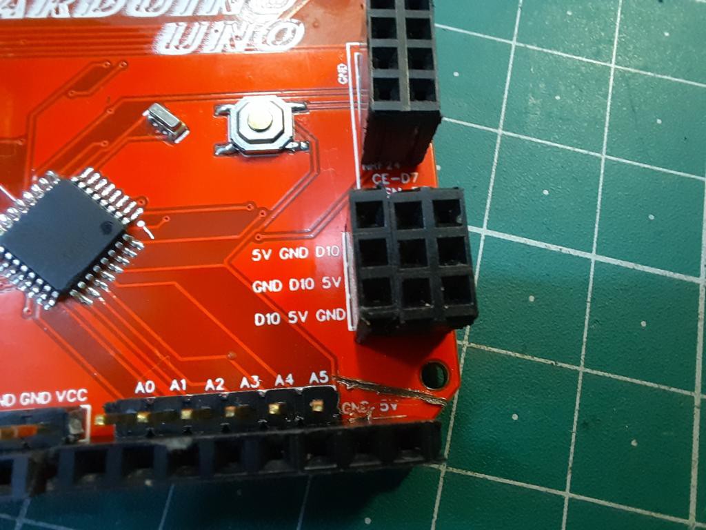
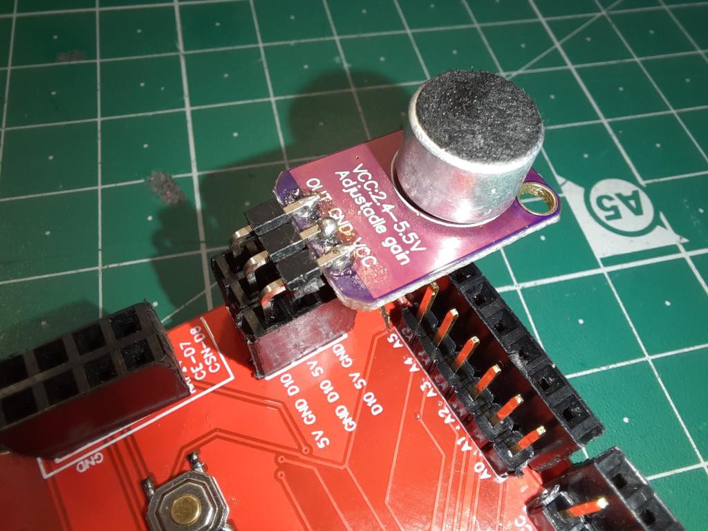
These are headers which is used to connect any digital sensor with 3 pins. Like DHT, microphone. No need to worry about the pin arrangement now. Because 3x3 headers form a total of 36 different probabilities to plug a module.
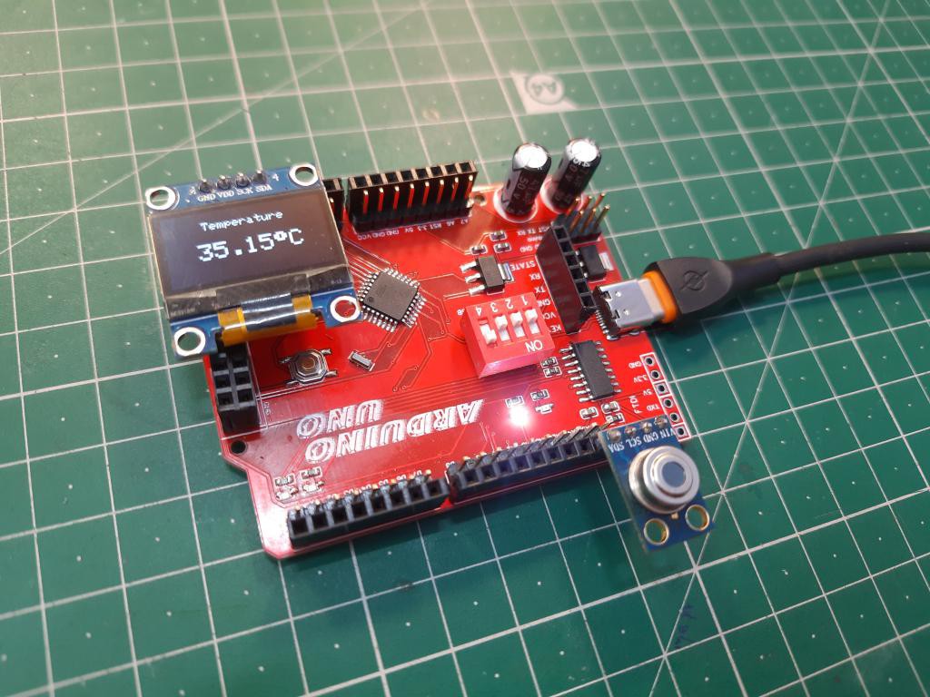
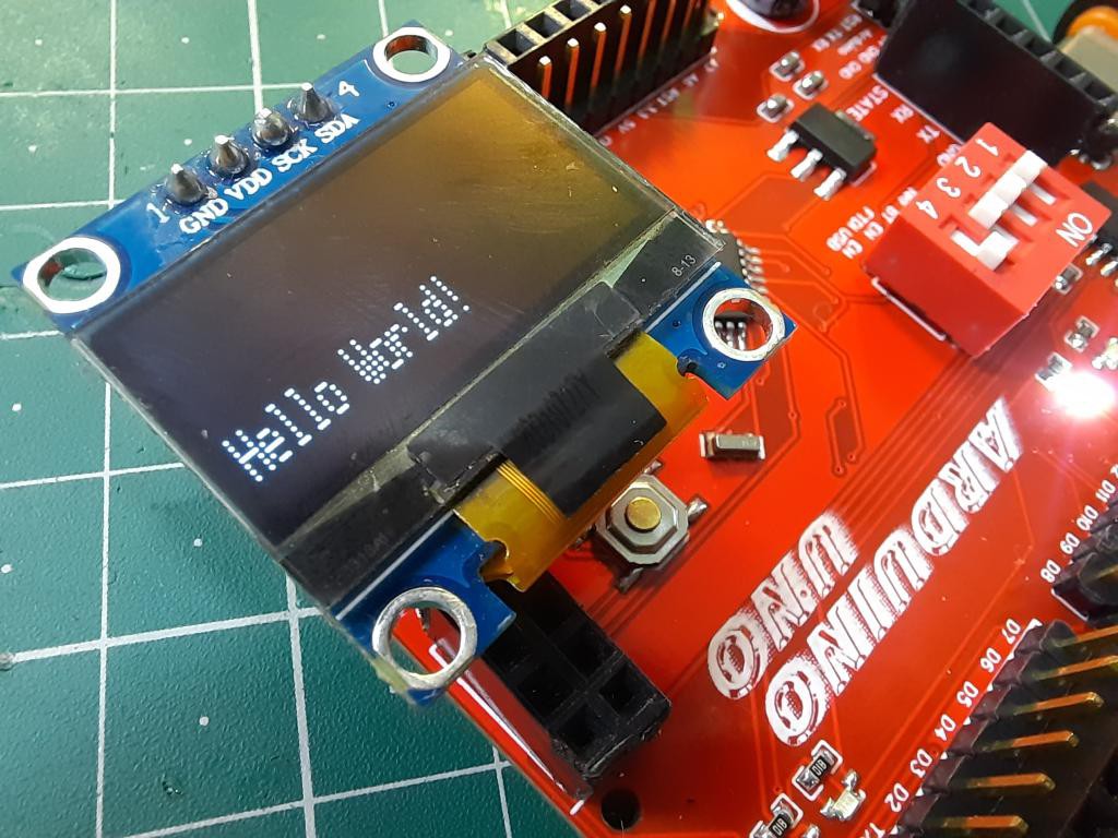
5) Direct 12C features:
Some of the display module and sensor use I2C communication with Arduino. Now you can plug the 12c screen directly into the board with any sensor to get the value displayed on screen. Download all the different programs used from here.
Troubleshooting:
If there is any problem in booting then check the serial connections. There may be issue in CH340 drivers or check the power connection of the chip. Ch340C troubleshooting and Arduino interfacing is explained in this separate article.
More project from us: