 Scott Feldman
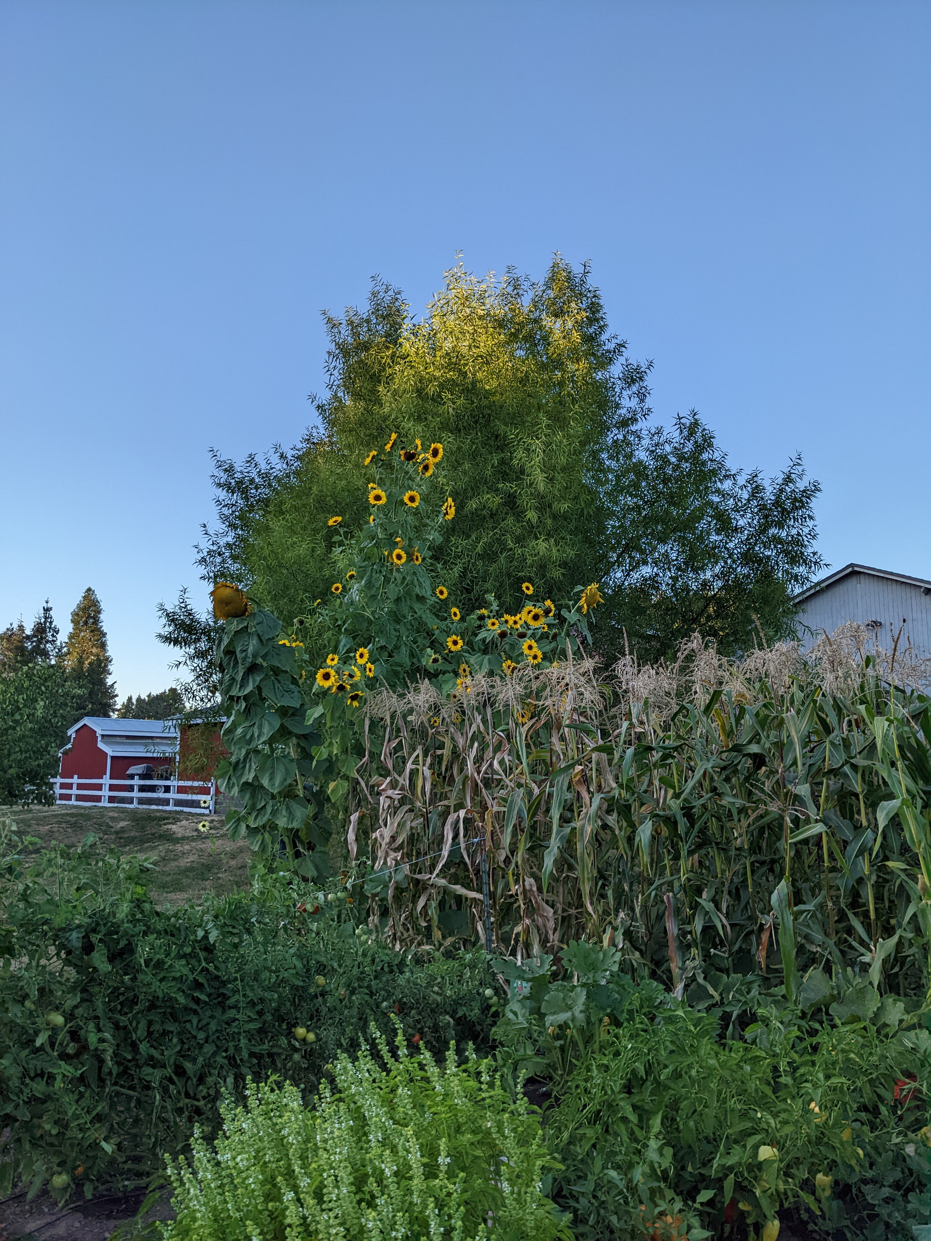
In communities where water is limited, due to usage restrictions or availability, every drop counts. This project is a watering system that delivers an exact volume of water to a garden plot, scheduled and configured by a gardener with a cell phone. Dispensing water in exact volumes and using efficient delivery mechanisms such as drip irrigation maximizes community water resources.
California USA has these restrictions right now.
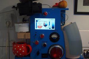
Click on the picture below to run a Demo of the system.
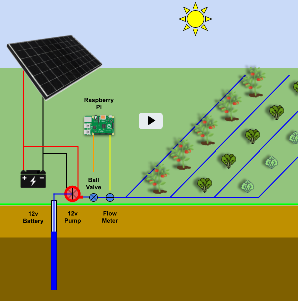
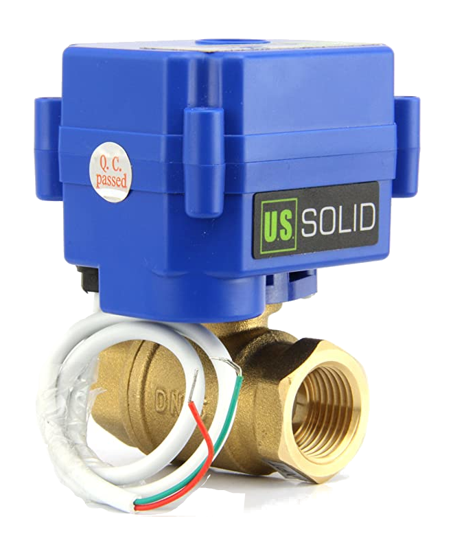
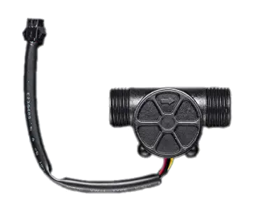
The system is off-grid, using a solar panel/battery combination for 12v power. A 12v diaphragm pump pumps water on-demand when a ball valve opens. A hall-effect flow meter measures the volume of water pumped to the garden.
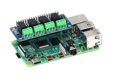
Off-grid power is easy enough to supply with the solar/panel combination, but what about off-grid communication to monitor and control the watering system? We solve this problem by configuring the Raspberry Pi to run as a standalone WiFi access point, allowing anyone with a cell phone or other device to connect to the WiFi access point and browse to http://10.0.0.1.
Electrical/Mechanical Diagram
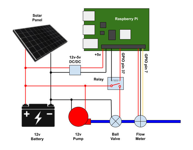
The ball valve is opened and closed using a relay controlled by GPIO pin 37 on the Raspberry Pi. The Raspberry Pi samples the flow meter on GPIO pin 7.
A DC/DC converter supplies the 5v power to the Raspberry Pi.
User Interface
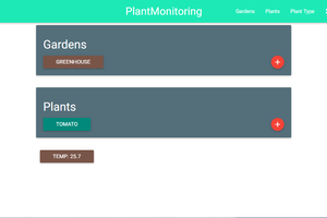
The Raspberry Pi is configured as a Wifi access point (AP), allowing the gardener to connect with their cell phone over Wifi and configure/control the system. Once connected, browsing to http://10.0.0.1 will show the user interface:
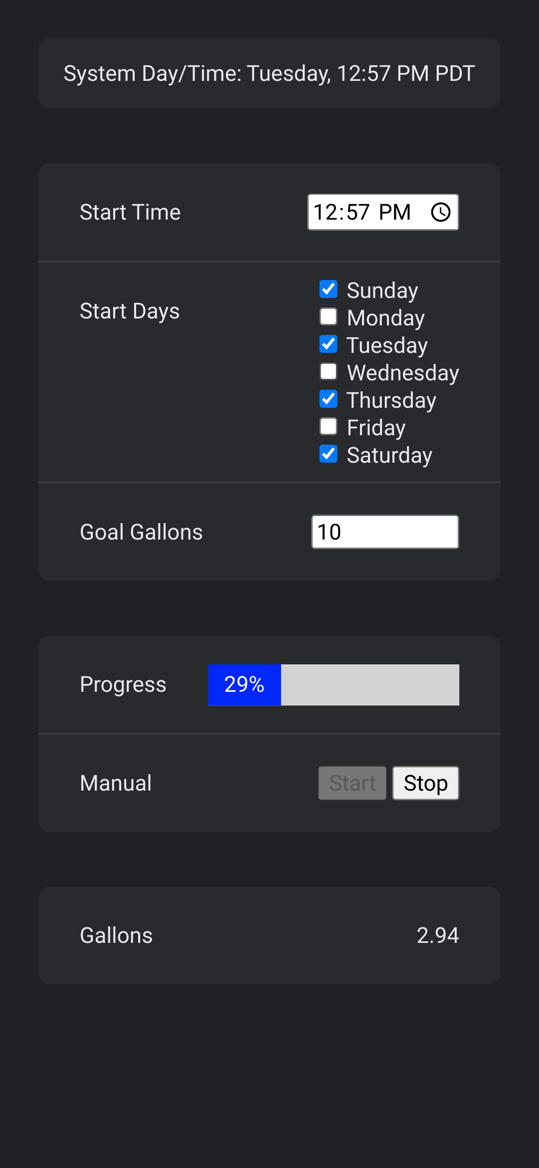
The gardener can set the days/time to start watering, as well as the goal gallons.
When the set day/time strikes, the system will open the ball valve and continuously sample the flow rate to calculate a running volume. Once the goal volume is reached, the ball valve will close, and the system is armed for the next day/time.
Manual override buttons are available to turn on/off the pump. This is useful when setting up the system to verify system functionality or to troubleshoot issues.
Software
The system software is written in Go programming language and is built with the Merle IoT framework and the Gobot framework.
The software is open source and is licensed under the BSD-3-Clause license. The source code is here.
The compiled software runs on the Raspberry Pi. In addition to controlling the ball valve and reading the flow meter, the software also runs as a web server, serving up the user interface shown above. The user interface lets the user change settings and observe progress.
User Interface Software
The HTML for the user interface is here. Pretty simple, just a bunch of nested divs with standard HTML5 elements.
The JavaScript for the user interface is here. (Not my favorite language to program in, and I'm constantly searching the web for JavaScript-isms). The main code opens a Websocket and listens for messages from the core code. Basically it's a state machine, where it uses the HTML elements to store state.
The CSS for the user interface is here. Bunch of flex boxes to layout the divs.
Core Go Code
The Go code that controls the ball valve and samples the flow meter is here. Look for the Subscribers() function at the bottom of the code. This looks very similar to the websocket loop in the JavaScript. Same messages are handled on both sides to maintain a notion of "state".
This code leverages the GoBot framework to read/write the GPIO pins on the Raspberry Pi.
The code is built with the Merle framework. The Merle framework provides the web server for the UI and handles all the messages passing on the websocket connecting the JavaScript UI front-end to the Go core back-end.
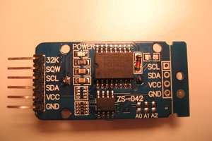
Sampling Flow Meter
Here's some facts:
- Flow meter sensor reads 450 pulses/Liter
- There are 3.78541...

 klhutchins
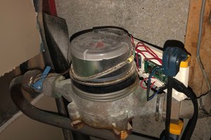
 AlfredC