 Electroniclovers123
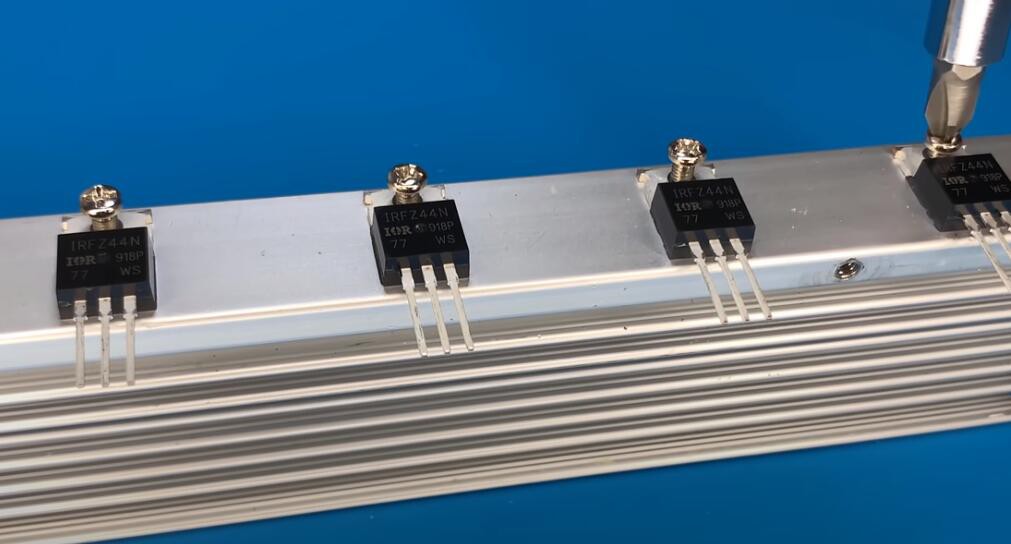
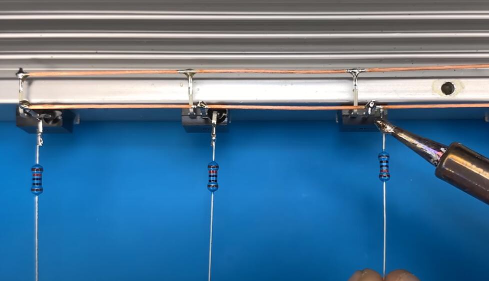
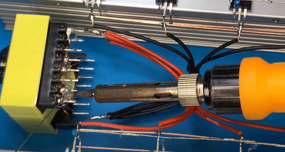
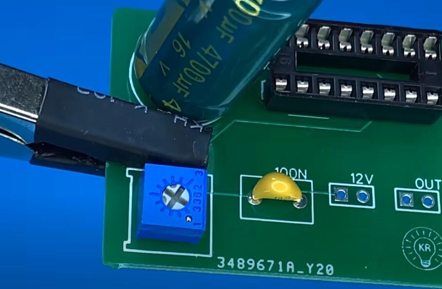
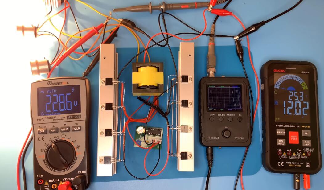
Today I will show to how to make How to make a simple inverter 2500W
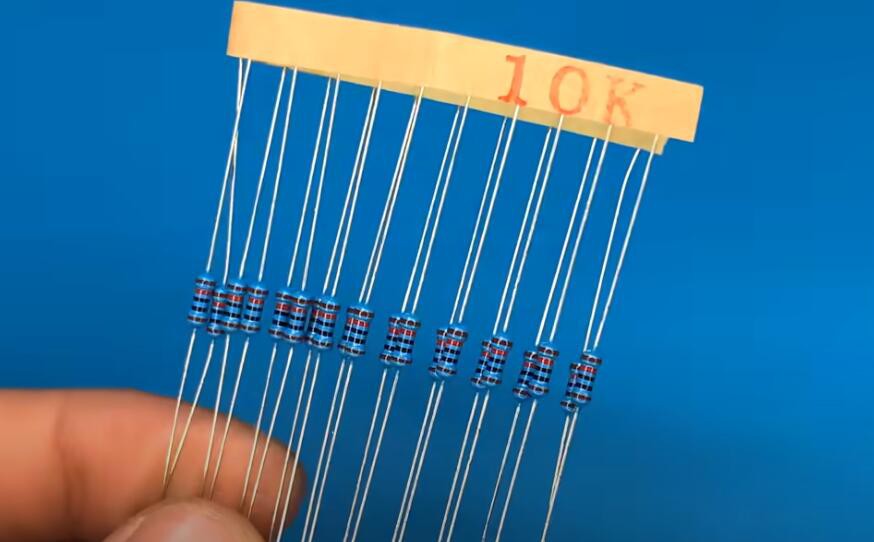
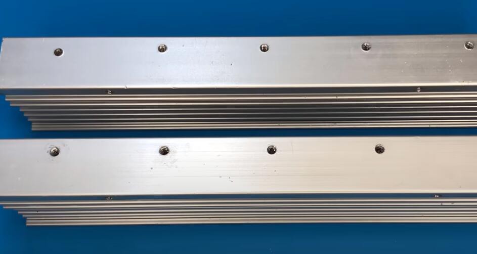
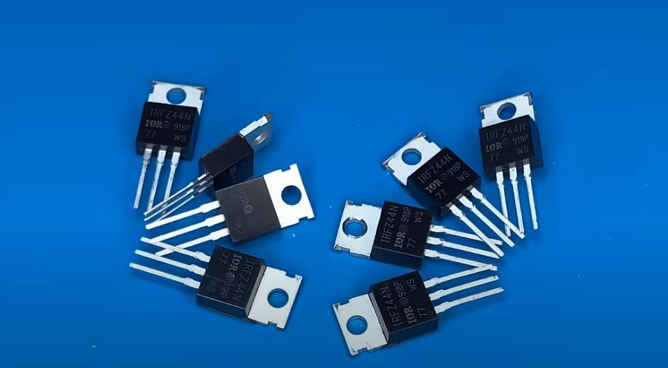
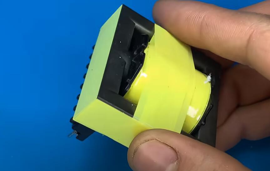
All the material you need for this project:
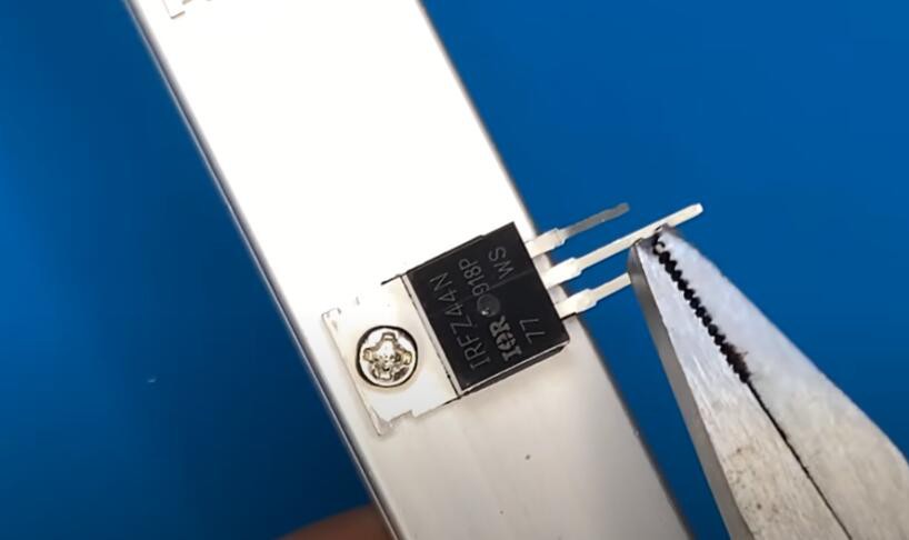
Here are the steps of this project:
1.
2.
3.
4.
5.
6.
7.
8.

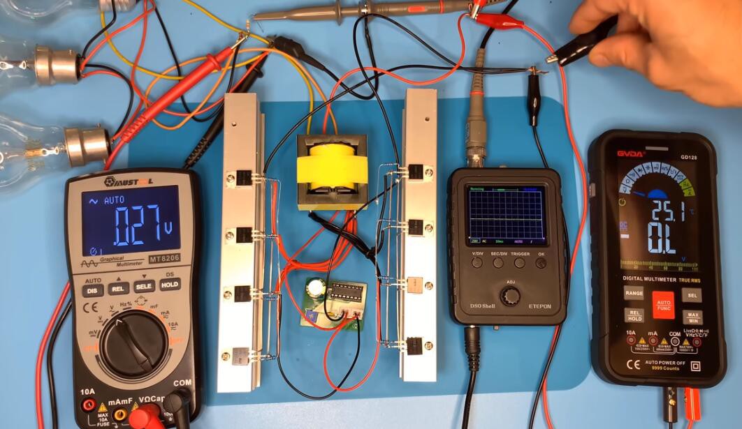
Show results:
The product links as below:
IC chips: https://www.utsource.net/category/ele...
Modules: https://www.utsource.net/Modules?sour...
Passive components: https://www.utsource.net/PassiveDevic...
Sensors: https://www.utsource.net/home/sensors...
LED lightings: https://www.utsource.net/category/led...
More electronic components you may be interested:
TLP181 https://www.utsource.net/itm/p/11222949.html
Product Attributes
Not found, similar datasheet recommended
Office Machine Programmable Controllers AC Adapter I/O Interface Board
The TOSHIBA mini flat coupler TLP181 is a small outline coupler, suitable for surface mount assembly.
TLP181 consist of a photo transistor optically coupled to a gallium arsenide infrared emitting diode. Since TLP181 is smaller than DIP package, it’s suitable for high-density surface mounting applications such as programmable controllers
● Collector?emitter voltage: 80V (min)
● Current transfer ratio: 50% (min) Rank GB: 100% (min)
● Isolation voltage: 3750Vrms (min)
● Operation Temperature:-55 to 110℃
● Safety Standards
UL recognized: UL1577, File No. E67349
cUL recognized: CSA Component Acceptance Service No. 5A
File No.E67349
● BSI approved: BS EN60065:2002, certificate No.8285
BS EN60950-1:2006 certificate No.8286
PC929 https://www.utsource.net/itm/p/11234605.html
TL431 https://www.utsource.net/itm/p/11205132.html
Product Attributes
Not found, similar datasheet recommended
The Integrated Circuit TL431 is a regulator diode with 3 terminals adjustable shunt regulation with the specified thermal stability and and applicable in the automotive, commercial and optimum temperature range applications. The output of the IC can be easily programmed with resistor adjusting and changing the values. The monolithic integrated circuit voltage operates at a low temperature coefficient of Zener diode easily programmable with the adjustable resistors. The negative and positive voltages are defined with the help of this IC reference.
The device exhibit wide range of current 1.0 mA to 100 mA with the dynamic resistance and impendence offering. The stable reference voltage is also taken to operate for the shunt regulator and it can be used as a positive or negative voltage reference.
Schematic and symbol representation of TL431:
SupplierFile/202006/24/f_b0a6a9c6dbed463ba0e76f359430b9fd.png
The symbol representation of the integrated circuit TL431 is shown below
SupplierFile/202006/24/f_c53f220ec9814da88d22709d35ffa985.png
This is the simple representation and schematic of the IC TL431. The pin configuration shows cathode, anode and the reference voltage pin.
Pinout configuration of TL431:
SupplierFile/202006/24/f_dcd09ca3f22a447ebec980f03f7e1aab.png
SupplierFile/202006/24/f_213173fdeab6469499c409da9a4ea188.png
Key Features of TL431:
1. The reference voltage tolerance is 25 degree Celsius
2. Low output noise
3. Sink current capability
4. Programmable Zener diode
5. Voltage tolerance is +4%
6. Output impedance offers is 0.22 Ohms
7. Available in 3 pin and 8 pin package
Applications of TL431:
As shown in the figure below it is used in the voltage comparator electronic circuit modules and switch mode power supplies for the best efficient power transmission and regulation of the electronic device.
SupplierFile/202006/24/f_94811776f03a4c8a8dd31e73e3710fed.png
TL431 Voltage comparator electronic circuit
1. It is used adjustable voltage and current referencing electronic circuit
2. switch mode power supplies
3. voltage comparators
4. voltage monitoring
5. Zener replacement
6. Isolated power supply circuits
LM339 https://www.utsource.net/itm/p/11199385.html
Product Attributes
Not found, similar datasheet recommended
Description
The LM339 is a complete remote control decoder in an 8 pin package. With the addition of a standard infrared receiver module, three individual outputs can be simultaneously controlled using a television remote control transmitter. This circuit responds to Sony television control codes, chosen because most universal remotes default to them when initially powered up.
The LM339 continuously monitors the stream of data from an infrared receiver module looking for these Sony type remote control codes. If an appropriate three digit code is detected, the selected output either turns on, turns off, or switches its state.
Features
● Low power CMOS design - typically 1mA at 5V
● Three separate outputs
● Pulse output for momentary controls
● Signal received output for visual feedback
● Easy interface to standard receiver modules
● Works with universal TV remote transmitters
● High current drive outputs - up to 25mA
Water Tank Level Indicator Using LM339
Project Overview
In this project we are going to discuss how to build a water tank level indicator using LM339 as the main component and using few other components. We are going to show four water levels using four LEDs. We are going to use all four differential comparators inside the LM339 IC. Let’s identify our main component LM339 and it’s characteristics.
What is LM339?
LM339 is a “Quad Differential Comparators”. In this quad means four hence the LM339 has four differential comparators in a single package.
What is a differential comparator?
Differential comparator is an operational amplifier configuration which compares two inputs and give an output according to the input voltage.
Output of the differential comparator is always either high or low it doesn’t give a discrete or analog output. Differential comparators have two inputs, named inverting input and non-inverting input. Symbol of a comparator is shown in the below image.
SupplierFile/202008/14/f_527b2585f2d543e1b62d005cf5f6f2f0.png
Figure1 Symbol of differential comparator
When the voltage level in inverting input is greater than non-inverting input differential comparator will output the low level (this is the voltage connected to -Vcc of the differential comparator). When the voltage level in non-inverting input is greater than voltage level in inverting input differential comparator will output the High level (this is the voltage connected to +Vcc of the differential comparator). Characteristic graph of input Vs output of a differential comparator like LM339 is given below.
SupplierFile/202008/14/f_2c819474f9af42eaba0f852cb31f562a.png
Figure2 Characteristic graph of input Vs output of a differential comparator
There is something special about the output of the LM339. It has open collector output. Which means when the output should be low the output pin will be connected to the GND as it should be. But when the output should be high it is not actually giving out any voltage it will act as a floating connection instead. A large resistance connected to Vcc is used to generate thins to a voltage level.
Pinout of LM339
LM339 come in 14 pin or 20 pin packages. As the 14 pin packages are most used, we are going to refer it. As mentioned before LM339 has four differential comparators inside. All four of these differential comparators are powered using a single power supply. Positive voltage input should be connected to the pin number 3 of the package. Pin 12 should be connected to the ground of the power supply. Each differential comparator in LM339 IC have 3 pins each. Below image shows the pinout of the 14 pin package of LM339 IC.
SupplierFile/202008/14/f_a1c5cffb3cce40f1a263538fa96efe06.png
Figure3 Pinout and physical look of LM339 IC
From the below image you can get a clear idea how the four differential comparators are configured and connected inside the IC.
SupplierFile/202008/14/f_05184fc888494a579b57858de840b0ba.png
Figure3 Differential comparator layout of LM339 IC
Main Components
Lets see what are the required components for our project and what are the purpose of the components.
● LM339 Quad Differential Comparators
● BC547 NPN Transistors
● LEDs (Green, Yellow and Red)
● 1MΩ Resistors
● 100kΩ Resistors
● 10kΩ Resistors
● 220Ω Resistors
● Bare copper wires (used as probes)
Let’s find out what are purposes of these main components.
● LM339 Quad Differential Comparators
As mentioned before this the component that sense the water level. To do that we need a voltage difference.
We are going to use the resistivity difference of the water and air to get this done. This will be explained later in the tutorial.
● BC547 NPN Transistors
LM339 can only drive loads which draws current less than 20mA. But some LEDs can draw more than 20mA of current it can be harmful to LM339 IC to directly drive the LEDs. That is where the BC547 transistor comes in to play. It can drive higher current load using the signal from the LM339 IC’s differential comparator output.
● LEDs and Resistors.
LEDs are used to indicate the water level sensed by LM339 and resistors are used for current limiting and create voltage dividers in this circuit
Circuit Diagram of LM339 Water Level Indicator
Shown below is the circuit diagram of the LM339 tank water level indicator circuit. If the tank is full all four LEDs will be turned ON, if three quarter of the tank is full only the bottom three LEDs will be turned ON. If half of the tank is full only the bottom two LEDs will be illuminated and if tank is filled just more than quarter only the bottom LED will be lit. if the tank is empty none of the LEDs will be illuminated.
SupplierFile/202008/14/f_8c3f0b58241643d1b9ae00c77b63957e.png
Figure 4 Circuit diagram
How this circuit works.
As you can see in above image there are five bare copper wires act as level probes. Longest one of these wires is connected to GND and other four are connected to one of the four differential comparators each, in the LM339 IC. R1 and R2 are forming a voltage divider of 2.5V it is fed in to inverting input of one of the comparators in LM339 and there R9 and water will form another voltage divider.
As water have less than 1MΩ resistance it will have less voltage than 2.5V that means when the probe is dip in water comparator output is set to logic low. This means R13 is connected to ground across the LM339 having a small voltage drop hence sending a base current to the BC547 transistor and LED is illuminated. All for differential comparators inside LM339 are connected to similar circuit to achieve four levels.
1N4007 https://www.utsource.net/itm/p/11200364.html
Product Attributes
Not found, similar datasheet recommended
FEATURES
● Low forward voltage drop
● High current capability
● High capability
● High surge current capability
● Exceeds environmental standards of MIL-S-19500/228
MECHANICAL DATA
Case : Molded plastic DO-41
Epoxy : UL 94V-O rate flame retardant
Lead : Axial leads , solderable per MIL-STD-202, method 208 guaranteed
Polarity : Color band denotes cathode end
Mounting position : Any
Weight : 0.012ounce, 0.33gram
For more details, pls check the video on youtube: