 Lithium ION
There are two methods to control the speed of motor, one through the step-down convertors-linear voltage regulation and second by controlling the PWM. There are many PWM controller available in market claiming up to 50Amperes of current. But today we are going to make our own PWM controller which can be used with high torque DC775 motor.
To generate the square signal, we are using NE555 IC in astable mode. Then a through a potentiometer width of the signal can be controlled which helps to control the speed. The high ampere control is possible only because of Mosfet switching. The full working of this type of PWM controller is described in the video embedded below.
After making the circuit layout, we will convert it to PCB and order the PCB from PCBWAY- reliable PCB manufacturer from China. PCBWAY offers 5pcs of 2layer PCB in just $5. Register now using this link to PCBWAY and get free new user coupons. Participate in PCB design contest and win upto $1500+ reward points.
Components required:
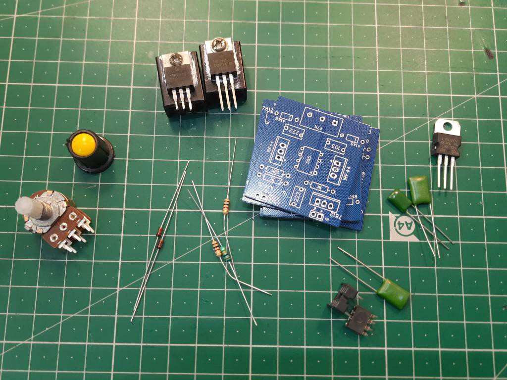
- 555 timer
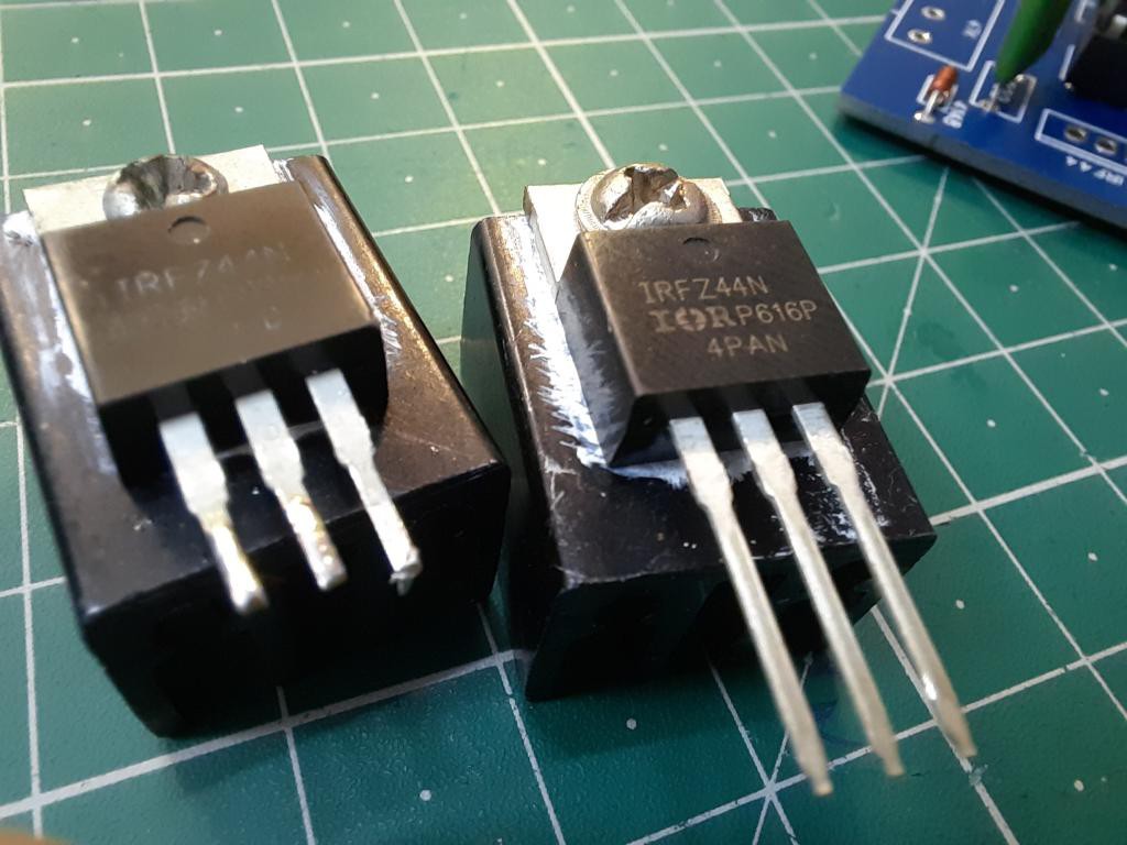
- IRFZ44N mosfet
- 47k potentiometer
- 222, 103 Ceramic capacitors
- 7812 voltage regulators
- 4148 diodes
- 1k and 10k resistors
- Pin headers
- Power supply
- Custom PCB from PCBWAY
Circuit diagram:
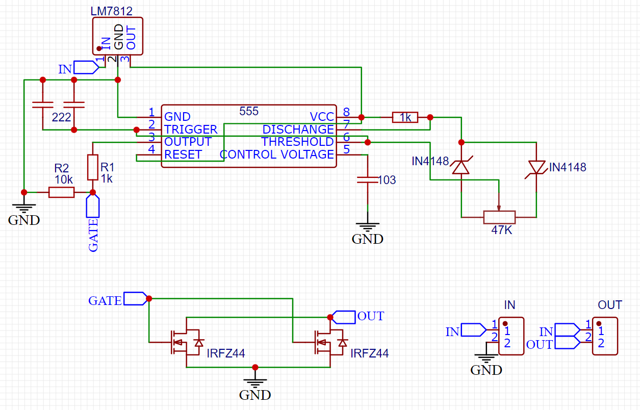
Ne555 is a timer IC, which generates the square wave PWM. The resistor 47k, 10k and 1k with 222 and 103 ceramic capacitors control the PWM signal. Which then fed to the Mosfet IRFZ44N which helps to drive the high-power appliances like motors and resistive loads.
7812 voltage regulator is used to give a constant voltage to 555 timer. 4148 diodes for the biasing purpose. All the system is made to be work on single PCB board.
PCB designs:
I designed the PCB files using the schematics given above. Generate the Gerber files and order the designs from PCBWAY just in $5 for 5 pcs. If you want to use the same designs then download the Gerber files from here.
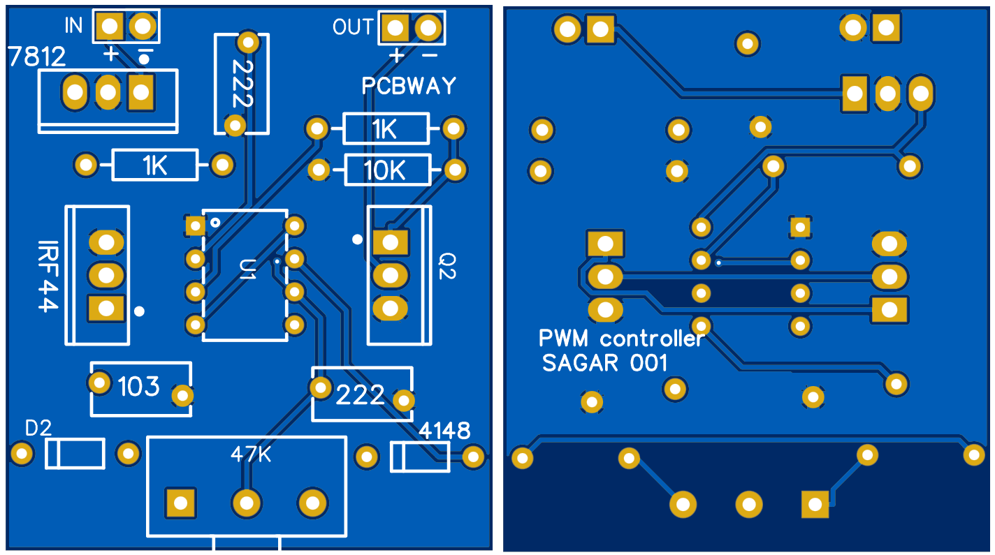
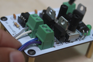
Everything is arranged in a very small form factor, still I am using pin headers for the input and output. But I will update the design soon which covers better arrangement of components (SMD) and atleast screw terminals for I/O section. I am using blue color, Hasl finish 1.6mm thickness FR4 for my project and to know more about the specs visit PCBWAY home page.
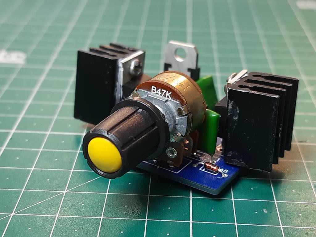
Assembling and soldering:
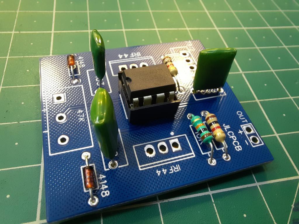
After getting the PCB files, I collected all the required components and start assembling. I always prefer to mount resistor and diodes first. Then go with the capacitors, IC, regulator, potentiometer and MOSFET. Mount a small heatsink on MOSFET for faster heat dissipation.
No need to use any type of fan on a load below 10amperes. These MOSFETS are made to work with very high power ratings. A simple soldering iron may do a very good job because this design doesn't have SMT components.
Working:
The PWM waveforms can be seen on oscilloscope, and by turning the potentiometer we can change the duty cycle of the wave. Which then increase/ reduce the ON time on Mosfet and hence the overall output can be controlled. Always connect the PWM controller to a filtered linear power supply unit or SMPS. Noise may cause PWM fluctuations and output can be disrupted.
There is one mistake in design, the potentiometer work in opposite direction. But the circuit is okay and working well. Here I also performed a test using DC775 motor. The overall duty cycle can be changed to 0 to 100%.
PCBWAY Contest Info :

PCBWAY 5th design contest is live, you can participate in this event and upload your designs to PCBWAY. There is price for everyone. The contest is divided into 3 categories:
1) Next Generation Hardware
2) Earth friendly project
3) free theme

And every participant is reward with RP2040 Raspberry Pi Pico board. You can see the project themes, rules, participation, submission and discussions from here.
 Mrinnovative
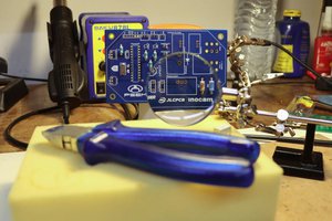
 psemportugal
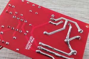
 ElectronicABC
 Pratik Makwana