 colton.baldridge
As I approached this project, I thought about what the best way would be to create a 3D mouse, particularly one for makers like myself. To be quite honest, the solution on the market is really good and works well. In that regard, I took a somewhat "if it works, don't fix it" approach to the design. My plan is to use a sensing PCB in the base to read the location of a floating knob above it (with very high accuracy). As shown in this teardown on the EEVblog forum, the mechanical solution they chose is rather elegant. Simply connect 3 springs with a nice stiffness to 3 points and blam, you've got a floating 6DOF flexure. For me, it's a bit different. I don't want users to have to go out of their way to buy specific springs, and since they're already using a 3D printer, I figure why not have them 3D print a flexure. I've been a bit obsessed after Veritasium's video on compliant mechanisms anyways.
So in terms of tackling this project, the most obvious challenge seemed to be designing said flexure. I don't know about you, but I'm an electrical engineer playing in a mechanical engineer's world, so the term "6DOF flexure" prompts equal parts interest and fear. My initial intuition to attack this problem was going to involve using the electronics PCB itself to do the 6DOF deforming, but considering how sensitive ceramic caps are to cracking, and that the feedback loop of trial/error would be really slow, I decided instead to 3D print the flexure (along with the knob and most everything else in this project). This would allow both rapid prototyping and user customization if they didn't like the stiffness of the default flexure.
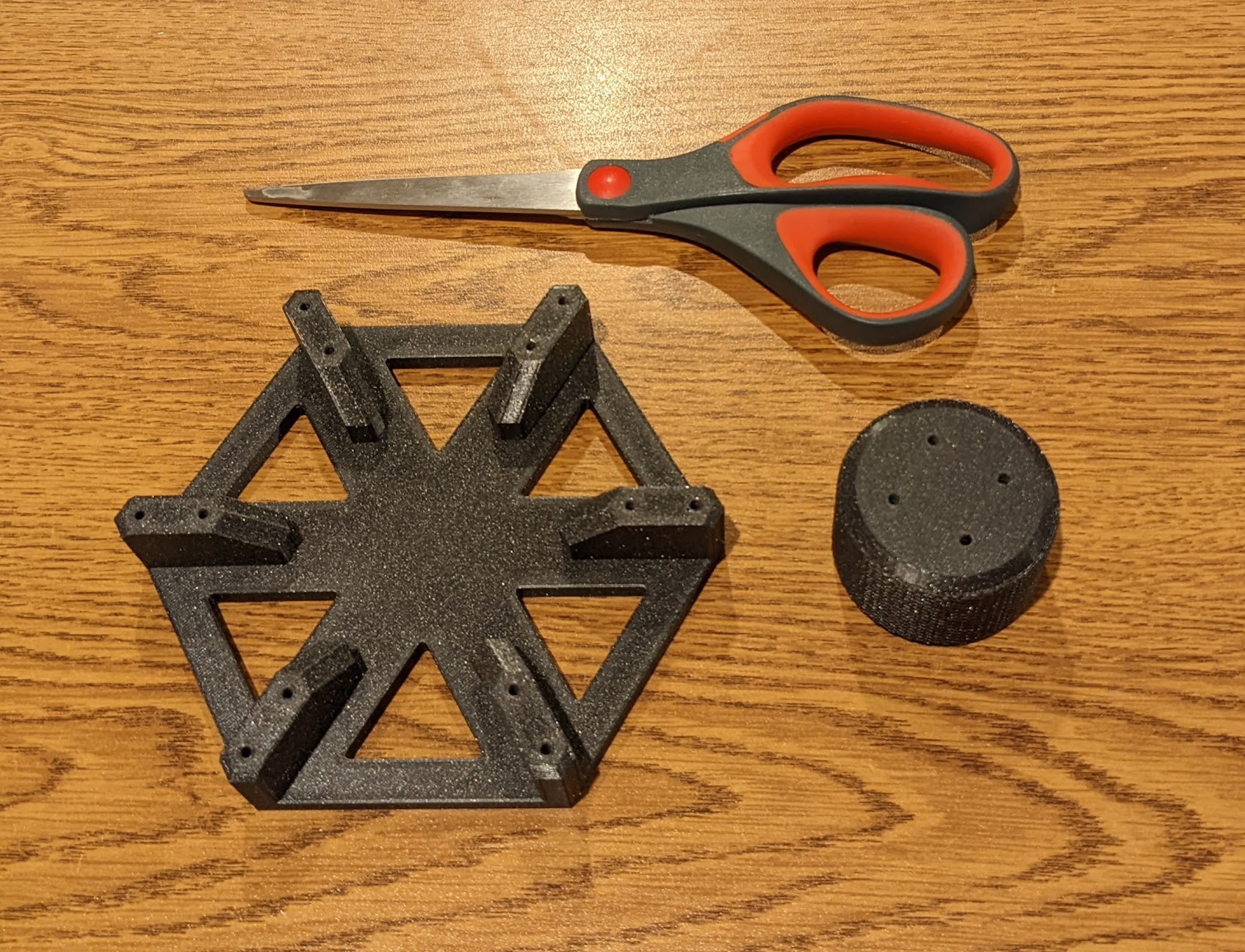
With that in mind I decided to take the most flexible approach to flexure design *ba-dum-tss*. I started by designing a knob and a base platform that I could interchangeably connect to different flexure designs:
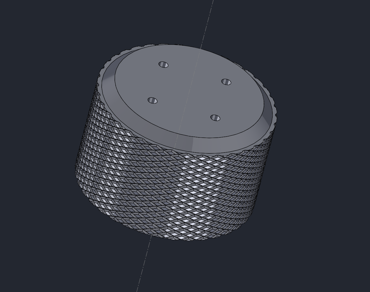
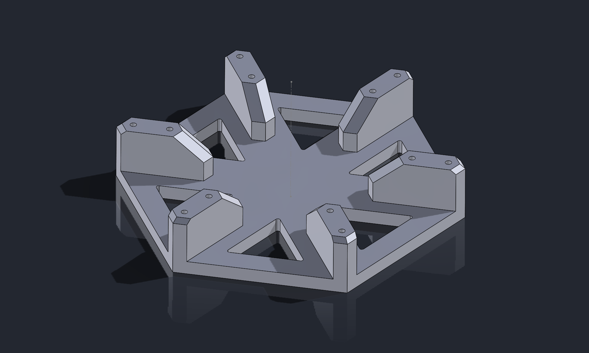
The platform offers two sets of mounting holes at r = 65mm and r = 50mm, and the knob has holes at r = 12.5mm. I printed both, and for the complete guestimates I made on size, they were quite good.
From there, I submerged myself in google searches trying to gain some understanding of what design might be best to start with. There are a plethora of interesting ideas out there, but many are based around actually driving a platform in 6DOF rather than just allowing motion. The closest thing to what I'm doing is a paper titled "A Decoupled 6-DOF Compliant Parallel Mechanism with Optimized Dynamic Characteristics Using Cellular Structure" which is available for free here: https://www.mdpi.com/2075-1702/9/1/5/pdf
Regrettably, by electrical brain does not possess anywhere near the amount of required mechanical engineering knowledge to parse what is going on here, but the photos certainly provide a great source of inspiration for my future flexure designs. And with that, I set off CAD-ing away at revision 0 of my flexure design.
Discussions
Become a Hackaday.io Member
Create an account to leave a comment. Already have an account? Log In.