 colton.baldridge
I originally intended this log to be titled "Fun With FEA." But, the deeper down the rabbit hole I got, the less fun I was having. Please, let this log be an example of what not to do if you're not a mechanical engineer, and how you shouldn't fall for the sunk cost fallacy.
It all started out with a pretty simple goal -- use Solidworks' (or some other open source alternative's) FEA tools to analyze flexure designs before 3D printing them. I felt that I had a pretty mature flexure design, and wanted to hone in the finer details. For example, I felt that it was slightly stiffer in the X translation DOF than in the Y translation DOF. I figured FEA would be the perfect tool to analytically capture this, and then iterate the design until stiffness was balanced. I planned on to create permutations that modified a few variables: flexure height, width, thickness of the connections to the mounting points, etc.
Solidworks actually makes it really easy to run a basic FEA simulation, so to start, I created a couple "studies," as they're called, where I moved the center mounting point 3mm in the X and Y directions and looked at the resulting forces on the knob mounting points. Effectively analyzing from the knob's perspective.
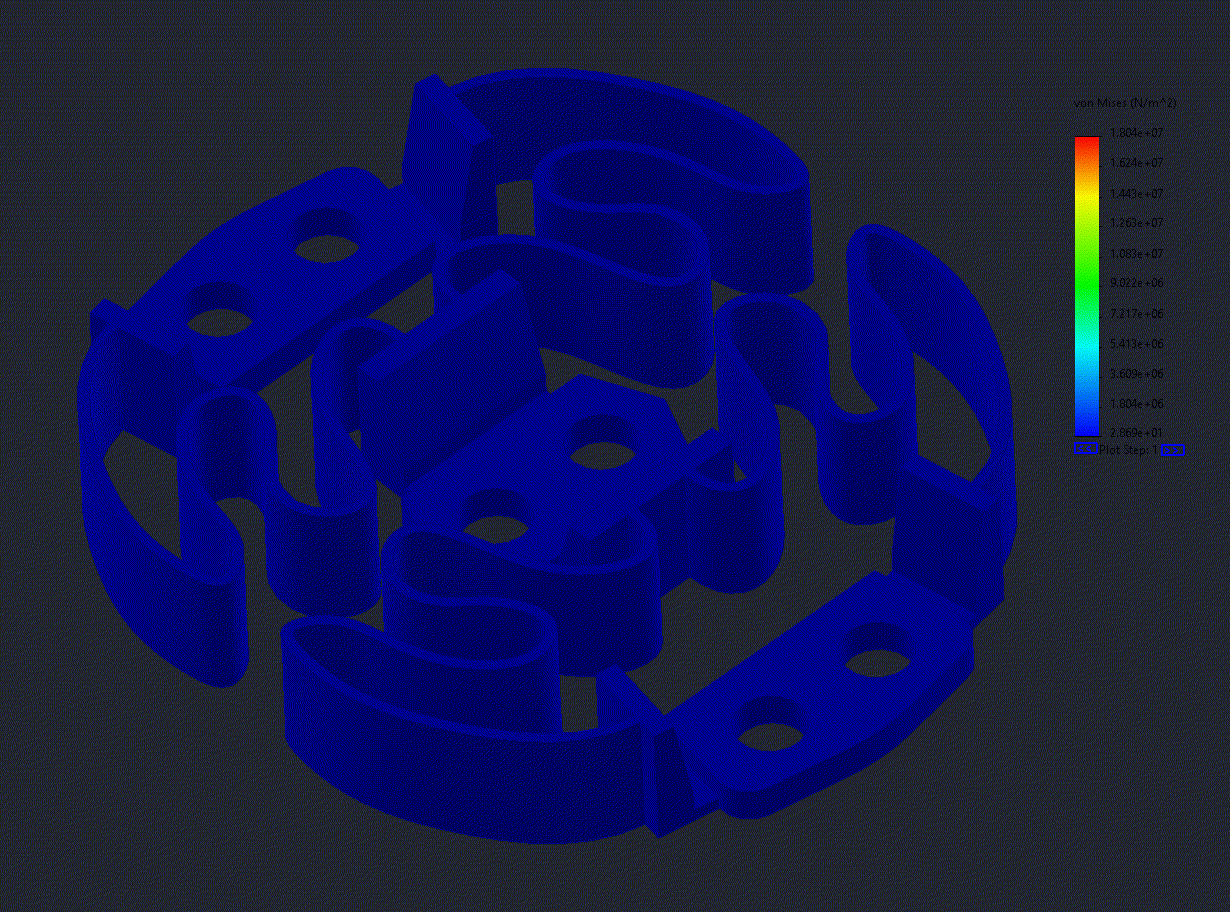
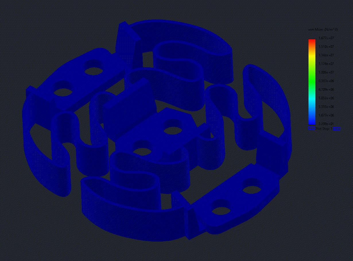
The outputs of these baseline studies aligned with my feel - the resultant force (assuming this part was made of isotropic ABS, a bold assumption, to be clear) was X_Translation: 2.40N, Y_Translation: 1.87N. A stronger force here means that the flexure is stiffer in that axis.
Now here is where I made my first mistake. In order to capture the resultant forces in Solidworks, you have to go through a dialog menu in each study, make several selections, click a couple buttons, then you can finally see the forces you want. So naturally, after my Google searches showed no simple way to do this in an automated fashion, I jumped ship to FreeCAD. With hindsight, I now know I should have persevered.
Moving to FreeCAD really opened up a whole other can of worms. It allowed me to do the above simulations relatively easily, but it took half a day to get up to speed and recreate the simulations. The bigger problem came when I went to expand them. You see, I didn't just want to capture X and Y translation for every permutation. I wanted to capture the forces for all 6 DOFs and try to balance them. FreeCAD, however, had other plans. You see, FreeCAD FEA is really only a frontend to a sim program called calculix. To spare you the details, it effectively proved impossible to do any of the pitch/roll/yaw simulations using this combination of FreeCAD/calculix. I did manage to get some sort of yaw simulation going, but felt that it was hacky at best (I was manually editing the txt input file FreeCAD passes to calculix) and gave me results I wasn't super confident in. Maybe there is a way to do what I wanted and I wasn't able to figure it out, but after spending another half a day digging through calculix documentation and manually editing text files before every run, I was ready to return to the more user-friendly Solidworks.
Thankfully, Solidworks makes it easy to do the pitch/roll/yaw simulations I wanted, and within a few hours, I got those working and the results showed something interesting.
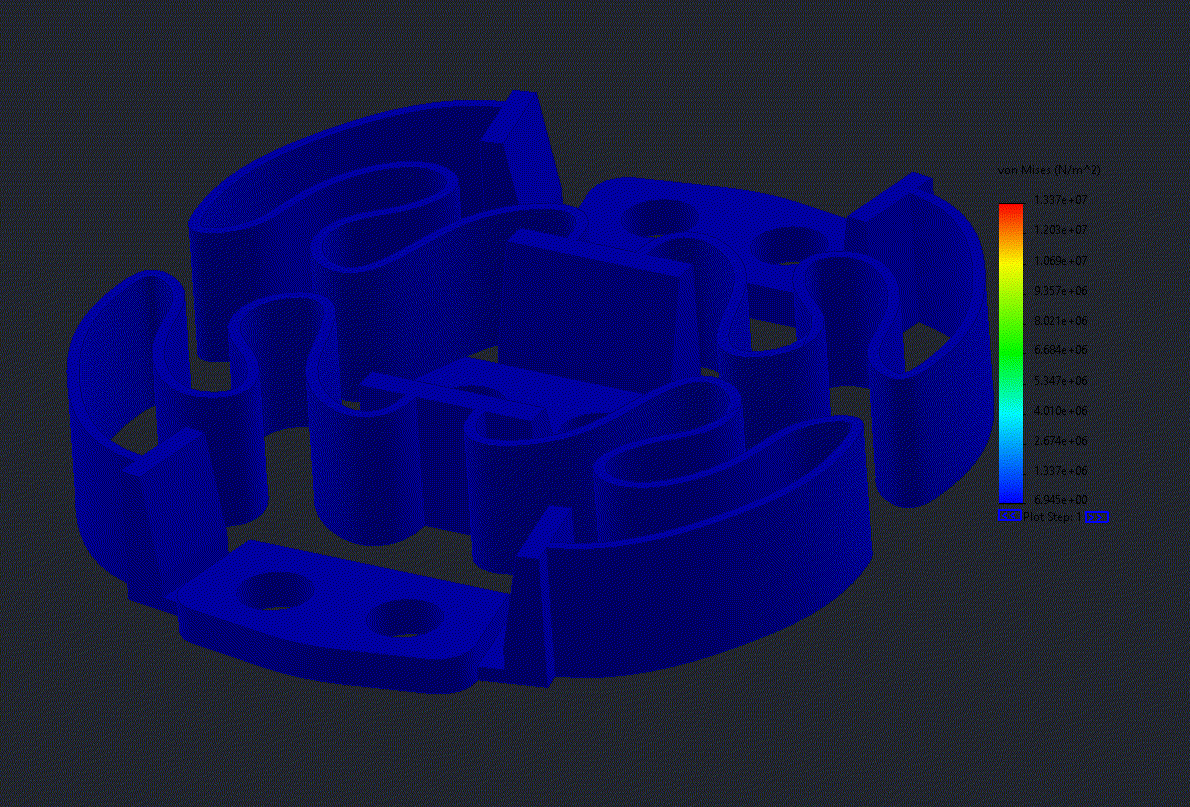
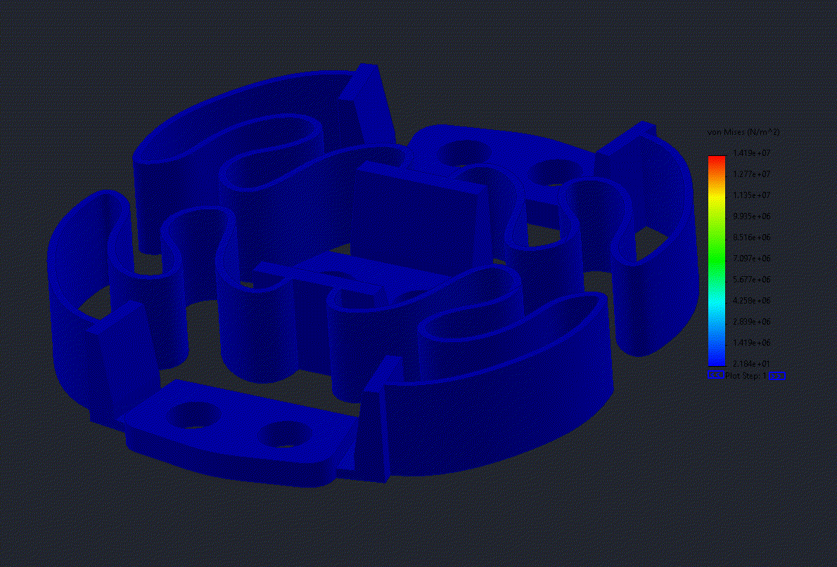
The results showed that the pitch and roll torques needed to create a 10deg rotation were almost identical, within 5% of each other. But, when I went to feel my 3D printed model in real life, they felt substantially different, like 30% more stiffness in one axis than the other. This tipped me off that something was wrong, but I persisted. I wanted to get this working no longer because it would be accurate (and thus practically useful), I wanted to get it working just to say I did FEA, and I already had spent a lot of time on it, I might as well do something cool like automate it, right?
So, from stage left, enter the Solidworks API written in none other than VBA. Now this is really where I should've stopped. Yet the curiosity and ego were already at their most powerful, and thus I continued. I spent over 20 hours cranking out a 150 line VBA script that did nothing more than update and run the studies for all 6DOFs, click the mounting points I wanted to gather the forces for, then print those forces to the console. I made one of the classic blunders, and fully embodied the below meme.

And with that I now have FEA that does not provide accurate results, but is fully automated such that if it did provide accurate results, it would be useful.
My plan going forward is the same as the old plan. I need to make a couple smaller iterations on the flexure design to get the feeling in all 6 DOFs balanced, and then will shift back to my home turf, and do some electrical design and layout.
Discussions
Become a Hackaday.io Member
Create an account to leave a comment. Already have an account? Log In.
😅
Are you sure? yes | no