 colton.baldridge
True to my last log, I ended up only making a few (ahem, more like 7, but who's counting?) more revisions to the flexure before calling it good enough. Unfortunately, in doing so, I realize that what I've created is more of a 3D printer torture test.
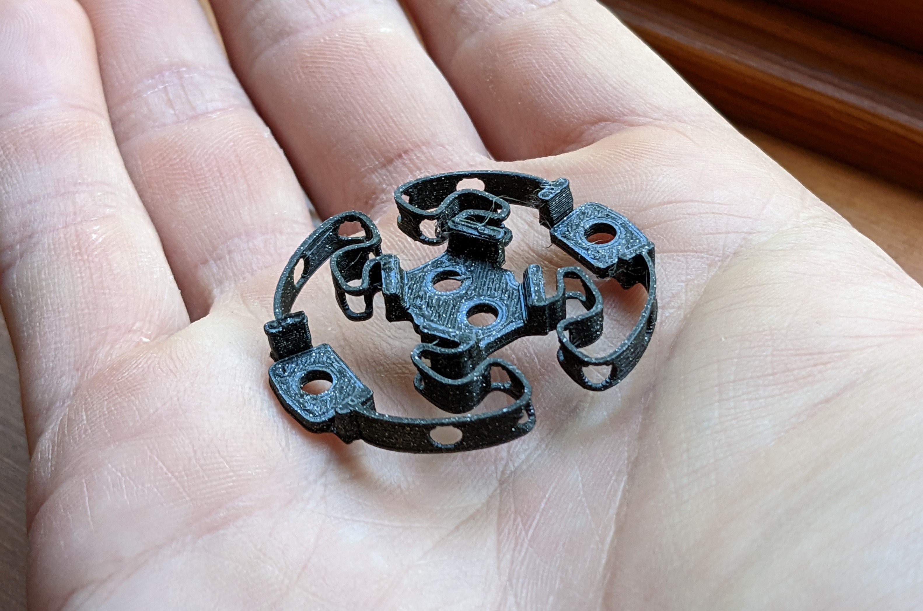
As you can see, the bendy parts of the flexure are a mere 0.5mm thick, with several holes placed in them. My Prusa mini has actually been printing these with a 100% success rate (lots of iterations on hole location and other factors) but I worry about releasing this for others to try to print, as I've spent a lot of time with less reliable printers and know the pain of failed print after failed print.
This has inclined me to start considering alternate solutions. I'd like to still keep the flexure 3D printed, but if I'm unable to come up with a reliably printable design, swapping to metal springs might be the easy way out.
For now though, this god-forsaken solution is going to be the one to stay, as I really need to keep moving forward with the project. I don't want to fall into the trap of perfectionism, and I'd really like to get to my bread and butter -- electrical design.
To keep moving, I started thinking about what features the final base should have. Up to this point I've just been using a small spire of an adapter that has been taped down to my desk. But, for this to be a real product, I'd need the base to be able hold a PCB, and it would be especially nice if it could look good while doing so. Additionally, I've been thinking more about what the capabilities of this mouse should be. Something that I think is really interesting on the commercial solution is the inclusion of buttons and even a display on the highest end model. This inspired me to add an additional requirement that this base should include some sort of modularity. I've been inspired by a lot of open-source mechanical keyboards in the fact that they often break out bonus functionality using I2C over a headphone jack. I think that would be super cool to support accessories like the ones mentioned above. I probably won't start with including it, as there is a lot of technical risk already associated with my current electrical approach, but once I buy down some of that risk, I'll roll in an exposed I2C bus on a future revision.
And after having these many thoughts, I designed the first revision on the base:
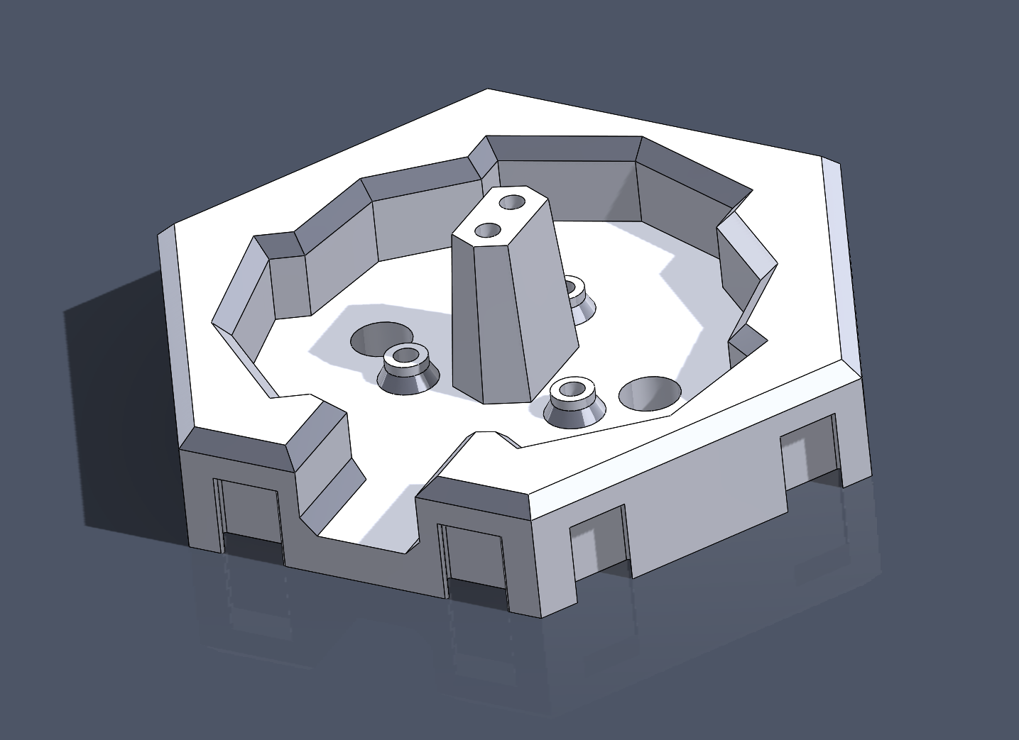
To understand the design I have here, you first have to understand the plans for the electrical side of this mouse. My thinking is that I can use some of TI's super cool inductance to digital sensors to read the position of metal objects within the knob. Using 6 coils/sensors (needed to determine the 6DOFs) in 3 pairs, I can use the math associated with a Stewart platform to back out the position/rotation of the mouse, like so:

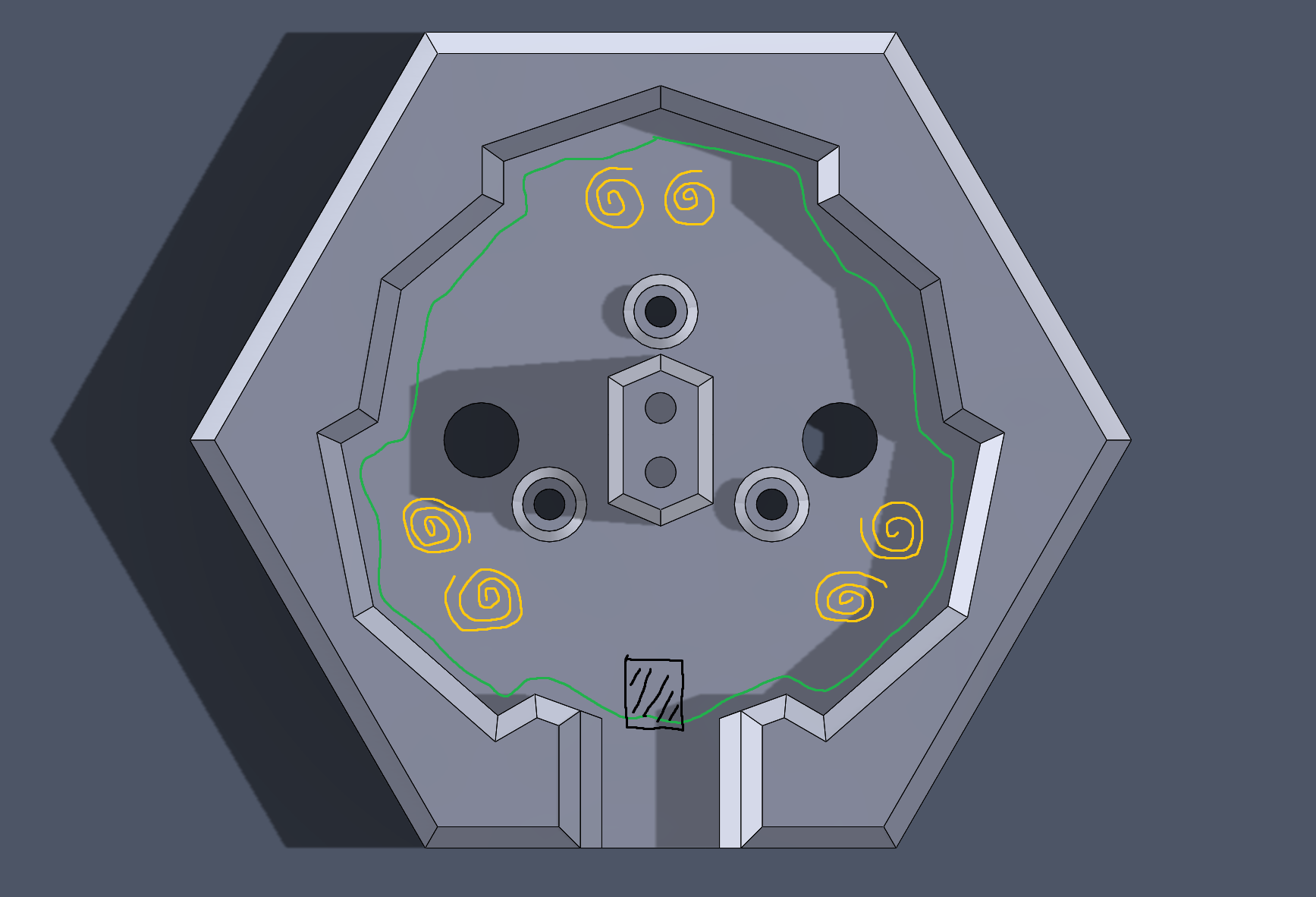
The only variables here are the lengths of the actuators, so if I can back out the kinematics of the system, I can determine the translation/rotation of the mobile platform (in our case, the knob). This wondrous MS paint drawing shows roughly the plan for the PCB:
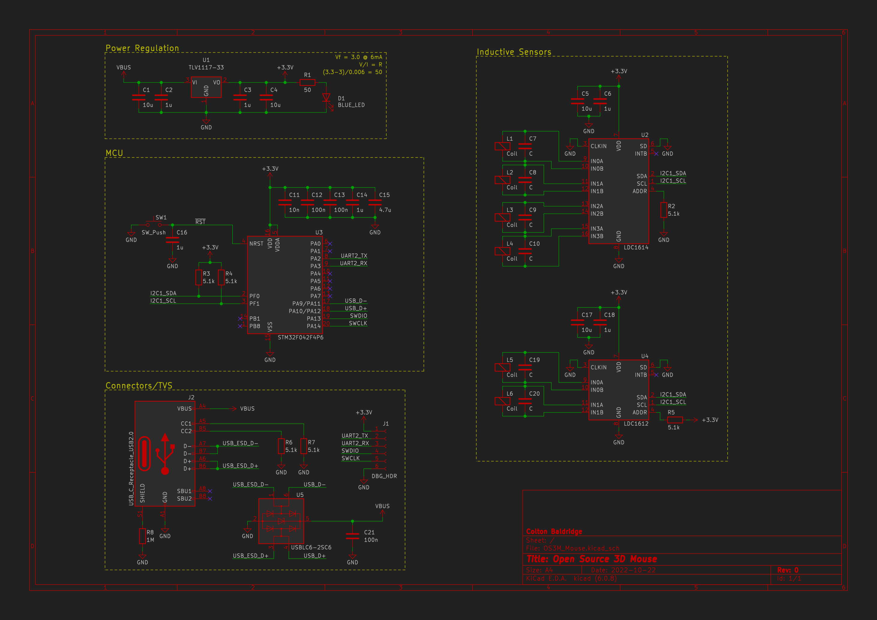
And with that, I've set away at making the PCB. The schematic is actually already mostly done, so I'm hoping to have hardware in hand sometime in the next couple weeks (we'll see about that timeline, lol).
As an added bonus, I've attached the .sldprt and .3mf of the latest flexure, base, and knob to the project. There are a couple caveats though:
- If you're using PrusaSlicer, you must use the classic perimeter generator, otherwise the bendy parts of the flexure don't get incorporated to the rest of the flexure. (I have not tested other slicers)
- Settings -> Layers and perimeters -> Advanced -> Perimeter generator = Classic
- All you should need are 4 M3x10mm fasteners to put it together. The hole sizes are made such that the screws self-tap. Be sure to tap the holes before trying to assemble! If you are having trouble, just open up the .sldprt and make the holes a little smaller/bigger.
Please give it a try! Let me know if your printer is up to the task!
Discussions
Become a Hackaday.io Member
Create an account to leave a comment. Already have an account? Log In.