Silícios Lab
For a long time we developed several prototypes and teaching kits of mobile robots and we always used different modules to build them.
Among these modules, we highlight: module to drive motors, module TP4056 to charge the project's batteries, an Arduino board and a shield for connecting the wires to the Arduino's digital inputs.
This amount of modules often generates problems with bad connections and also makes connections more complex, with more wires. Also, they are not feasible to build a prototype or commercial product.
After all, what to do to reduce the number of modules in the construction of mobile robot teaching kits?
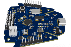
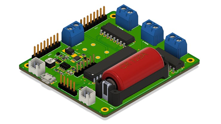
Based on this problem, we developed a circuit board with several features that will allow you to control your mobile robot. See the picture below.
What features have been implemented in this electronic board?
Below we have all the functionalities implemented in the electronic board.
- Charging system for Li-Ion battery with IC TP4056,
- DC-DC Boost Converter Circuit with 6V output,
- L293D Driver Circuit for the Motors, and
- Arduino Standalone Circuit with the ATMEGA328P.
Below we will present in detail all these functionalities implemented from the electronic schematic of the project.
Control Board Electronic Schematic
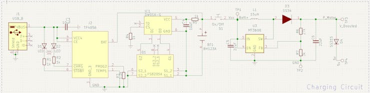
The electronic circuit was divided into 4 parts: battery charging circuit, motor drive drivers, ATMEGA328P control circuit, circuit connectors and fixing holes.
Below we have the electronic schematic of the project.
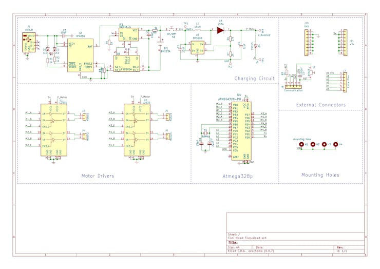
Next, we will discuss each part of the circuit and how it works in the mobile robot control process.
Mobile Robot Battery Charging Circuit
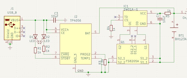
Many users who program mobile robots constantly need to remove the batteries from the project to charge it. This process requires opening the robot and an external charger for charging.
In addition, 2 18650 batteries are usually used to supply a voltage of 7.4V for project power. This requires more internal space and financial cost of 2 batteries.
How to solve this problem?
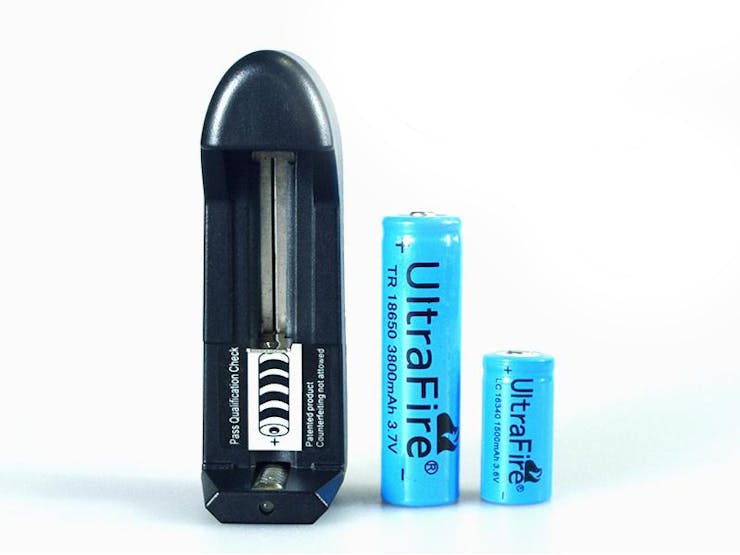
The first step for this was to create a circuit for charging Li-Ion battery with IC TP4056. The circuit structure is shown in the figure below.
Before implementing the charging circuit, we want to use only 1 3.7V Li-Ion 16340 battery to power the project.
In addition to avoiding the use of 2 18650 batteries, it will allow us to reduce the space consumed in the electronic board structure and in the prototype.
However, how do we supply the ATMEGA328P chip with +5V and the motors with +6V?
This question will be answered below.
First, we implement the charging circuit with IC TP4056. It will be used to control and transfer energy to the 16340 Li-Ion battery.
In addition to it, we use the DW01-A CI to ensure safety against overloads and short circuits during the battery charging process. In the electronic diagram of the figure above we have the battery represented by the BT1 element.
After the battery we insert a JST connector to insert an ON/OFF button. This allows you to turn the project control circuit on and off. Now, let's go back and answer the previous question: how to power the ATMEGA328P chip with +5V and the motors with +6V?
This lifting process is done through the circuit below. What circuit is this and how does it work?
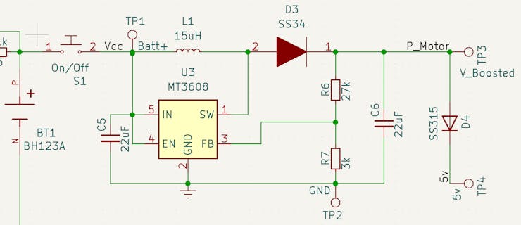
The circuit above is a boost type DC-DC converter. It has the purpose of raising the input DC voltage to another DC voltage level at the output.
For this project we are raising the battery voltage from +3.7V to +6V.
All of the above elements were calculated to provide this voltage. The MT3608 CHIP is the circuit's STEP-UP converter. Access the datasheet through this link.
At the output of the +6V power circuit, we insert an SS315 diode to provide a voltage drop of 0.95V. This allows us to...
Read more »
 Hulk
Hulk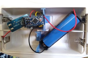
 Brian Gilbert