Jithin Sanal
Hey guys, in this video, we will be making a compact circuit that can be fitted in a glove to control Robots using Gesture commands. It’s really cool to control a pick and place robot completely using hand gestures right? I have been making gesture controlled robot and controlling it using a flex sensor and accelerometer.
Then I thought of replacing the flex sensor with a hall effect sensor. Why? Because we can easily fix it inside the glove and the switching can be done more efficiently. So let’s take a look at the circuit.
Circuit
Here you will see a voltage input terminal, Vin gloves, where I can connect a 9-volt battery or a DC power adaptor. This voltage input is connected to a 7805 voltage regulator which will convert an unregulated DC voltage of 7 to 32 volt to 5 volt DC power supply. This 5 V is then connected to Arduino, HC12 Wireless module, Indicator LED as well as the accelerometer.
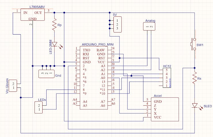
For this project, I decided to go with Arduino Pro Mini because of its small size. But of course, you can use any Arduino board for this project.
IO pins 8 and 9 are connected to two terminals where I was planning on connecting some 5 V LEDs. X and Y output of the accelerometer is connected to analog pins a0 and a1 of Arduino.
These are some headers that are connected to the analog pins of Arduino in this PCB. The reason why I added that is to connect 2 analog hall effect sensors. I will be using one of them to close and open the claw and the other to switch between control of the robot and control of the claw. And here is another switch which can manually trigger a switching action.
Basically, that’s all I needed for this project. If you are planning on making it, make sure you try it out on a breadboard and once you get the output you can use it as such or create your own PCB.
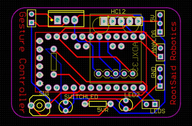
I personally like PCBs. PCBs are neat and help to get rid of all nasty wires hanging around. And it’s cool to make your own PCBs for your project right? Once the circuit was finished and tested, I designed a compact PCB using Altium, where I can fix all the components neatly. Here you can see routing is on both sides of the board which means it is a dual-layer PCB.
Getting PCBs Done
I ordered my PCB from PCBWay. PCBWay is a PCB manufacturer specializing in PCB prototyping, low-volume production, and neat and tidy PCB Assembly. To order your PCB from PCB way, Go to the PCBWay website and fill in the basic board details in the instant order form.
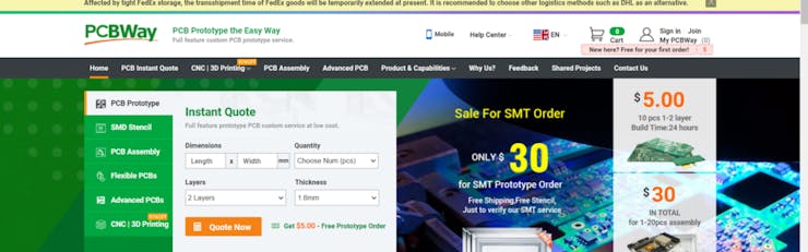
And in the next screen, you can completely customize your PCB. You can change the thickness, change the solder mask color as well as the silkscreen color, materials used, you can customize it in every way possible. Corresponding prices will be updated here in real-time. In PCBWay, you can even manufacture your PCBs with TG 150-160 for the same prices as that of TG 130-140 which means your PCB will be able to operate at high temperatures without any damage.
In the next screen, you should be able to upload your Gerber file and submit it for review. Once the review is completed, all that is left is to add to the cart, make the payment, and wait for your PCBs to arrive.
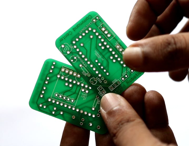
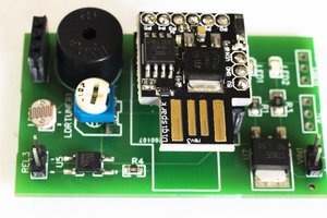
Once you get all the components and the PCB, it’s time for you to solder them together. Solder all the components onto the board and make sure to check the polarity of the components. After soldering the PCB looks like this. And this is it. This one is small and I think it will fit nicely on top of the glove.
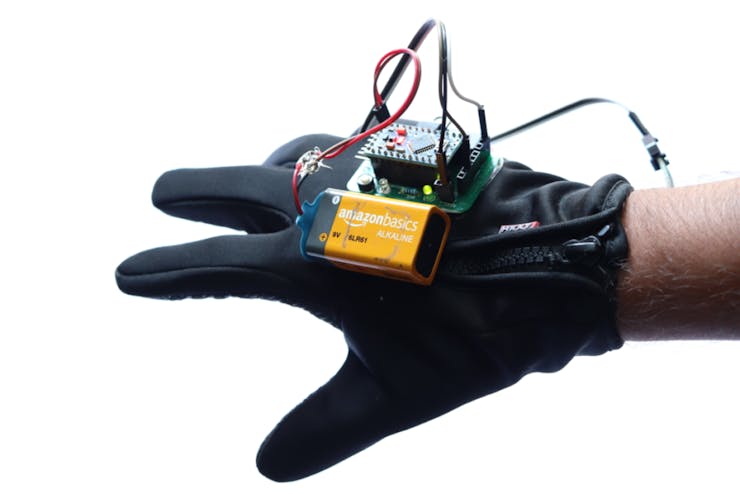
Working Explained
Here is the assembled board. On top, we have Arduino pro mini, a switch, a 7805 regulator, and some header pins where we can connect the hall effect sensors. Below we have the ADXL335 accelerometer which will sense the tilt. The output of the sensor is wired directly to the Arduino. And on top, here, we will connect the wireless module. For this project, I will be using an HC 12 wireless module which...
Read more »