# VFD daughter board
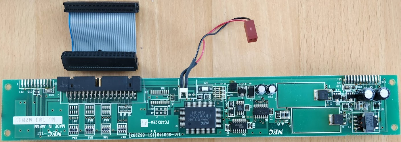
I probably don't need to investigate this too much as it is a stock component; a NEC FC40X2EA-AB with 2 lines of 40 characters and a serial interface. I just wanted to include the pics for you.


I have not yet found the datasheet for this specific character display, but I have the ones for the related single-line 20-character (FC20X1SA) and 2x20-character (FC20X2JA) boards. I expect the control interface will be identical; the daughter board has a 9600 baud serial interface and a power supply socket. Apparently, the 1x20 VFD requires 4.75-5.25V and draws 700mA, which frankly is less than I expected -- just shows how little I really know.
## My implementation
I've grabbed another old floppy drive cable and picked it apart. For one thing, this allows me to prototype things with my existing board by using this cable in place of the one for the keyboard. For another, the display doesn't require so many leads, leaving plenty of capacity to be used for interfacing with the 18 lighted key switches, the six rotary encoders, and the trackball.
On the VFD daughter board, all of the even-numbered pins are connected, and so my ribbon only provides GND on pin 34. Since I am using the serial data connection, I also don't need the 8 pins for parallel data. Additionally, after using the "T(0)" test mode signal to verify that the display is, in fact, functional, I have no further use for it. Finally, the "CS" should always be set low (which makes me wonder why it's even there?) so it will be simply connected to GND on the VFD side. In total, I need 6 leads (and only 5 Teensy pins) to drive the VFD, leaving 28 leads free to be used later on.
I've spent some time experimenting with the protocol. There are still some odd bits where my code doesn't work even though I seem to have done everything to spec.
According to the datasheet, the 34-line ribbon cable is used as follows:
| Ribbon line | Signal |
|---|---|
| 34 | GND |
| 17 | WR, Write data to display (set high when sending commands, low when sending data) |
| 19 | A0, Activate input (set low while sending serial data, then set high) |
| 23 | Not connected: CS, Send command (should always be set low) |
| 25 | Not connected: T(0) (set high at power-on(!) to enable test mode) |
| 27 | Busy signal from VFD (unable to receive data when high) |
| 29 | BL (set low to blank display, high to unblank) |
| 33 | Rx, Serial data Active high. Data packet is one start bit ("0"), then 8 data bits (LSB...MSB), then one stop bit ("1"). |
It took me a while to figure out which signals were active high and which were active low, as this does not seem to agree with the datasheet. By the way, using the default 9600 baud setting means working with pulses of 105µs which the Teensy can easily churn out.
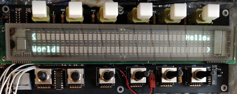
But hey, look at this beauty!

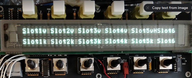
I've implemented some simplistic code to "put this string of text at this position", along with commands to control the cursor style and display brightness. The "Slot #" sequence shows a weakness: my display refresh code is not fast enough to provide real-time feedback when adjusting a value (say, volume control) using a rotary dial. This is because I am still struggling with absolute positioning; there is some oddity between how the datasheet says to use the "WR" signal to send commands, and how it actually works on my unit ... so for now I have to use relative positioning, which means sending the full 80 characters regardless of how much I actually wanna change. What I'm saying is, I should be able to make this much faster (at least 10x, possibly 60x) when I figure out the "WR" signal.


In this last image, you get an idea how the original system used to operate: the top row would have menus such as "colour balance" or "timing", and pressing one of the white buttons above would then load that menu, for instance showing "Black Level", "While Level", "Red", "Green", "Blue" in the top line and their individual values in the bottom line -- which could then be adjusted with the dial knobs and committed with the black buttons below them (not shown here, as they're physically part of the jog wheel board).
Next up: sensing the rotary dials and lighted switches, and controlling their lights.
 noughtnaut
Discussions
Become a Hackaday.io Member
Create an account to leave a comment. Already have an account? Log In.